SW420 GL BOARD Manual
Page 2
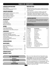
...18 Sequenced Access Management System (SAMS 19 Accessory Wiring 20-21 Control Board Illustration 22 Controller Programming and Features 23-24 Program Settings 25-26 TROUBLESHOOTING 27-28 MAINTENANCE Operator Maintenance 29 Single Phase Wiring Diagram 30 Repair Parts 31 Illustrated Parts 32 Safety Accessories for Secondary Entrapment Protection . . ...or death if you do not comply with the warnings that accompany it is unique, it . Refer to be comprehensive. HARDWARE KIT SW420 (K77-SW420) PART NO. 01-G0582 02-401-SP 07-2705 10-2111 11-2754 12-2727 40-3505 80-10026 80-206-65 80...
...18 Sequenced Access Management System (SAMS 19 Accessory Wiring 20-21 Control Board Illustration 22 Controller Programming and Features 23-24 Program Settings 25-26 TROUBLESHOOTING 27-28 MAINTENANCE Operator Maintenance 29 Single Phase Wiring Diagram 30 Repair Parts 31 Illustrated Parts 32 Safety Accessories for Secondary Entrapment Protection . . ...or death if you do not comply with the warnings that accompany it is unique, it . Refer to be comprehensive. HARDWARE KIT SW420 (K77-SW420) PART NO. 01-G0582 02-401-SP 07-2705 10-2111 11-2754 12-2727 40-3505 80-10026 80-206-65 80...
SW420 GL BOARD Manual
Page 22
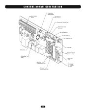
Relay Drive (not used) 22 CONTROL BOARD ILLUSTRATION Main Terminal Wiring J4 Connector Master/Second Dip Switch #4 Master/Second Potentiometer Timer-to-Close Potentiometer Force Adjustment Dip Switch #2 Dip Switch #1 Diagnostic LED J2 Connector J5 Connector SAMS Relay Drive Troubleshooting LEDs J1 Terminal Troubleshooting LEDs Limit LEDs Programming Port (factory use only) Motor Learn Button J3 Connector Aux.
Relay Drive (not used) 22 CONTROL BOARD ILLUSTRATION Main Terminal Wiring J4 Connector Master/Second Dip Switch #4 Master/Second Potentiometer Timer-to-Close Potentiometer Force Adjustment Dip Switch #2 Dip Switch #1 Diagnostic LED J2 Connector J5 Connector SAMS Relay Drive Troubleshooting LEDs J1 Terminal Troubleshooting LEDs Limit LEDs Programming Port (factory use only) Motor Learn Button J3 Connector Aux.
SW420 GL BOARD Manual
Page 24
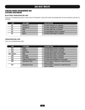
... A is activated On when Contactor B is activated On when SAM relay is activated On when Maglock relay is activated On when Alarm Relay is activated TROUBLESHOOTING LEDS There are 5 troubleshooting LEDs on relay drives K1 through K5. ADJUSTMENT CONTROL BOARD PROGRAMMING AND FEATURES (CONTINUED) RELAY DRIVE...
... A is activated On when Contactor B is activated On when SAM relay is activated On when Maglock relay is activated On when Alarm Relay is activated TROUBLESHOOTING LEDS There are 5 troubleshooting LEDs on relay drives K1 through K5. ADJUSTMENT CONTROL BOARD PROGRAMMING AND FEATURES (CONTINUED) RELAY DRIVE...

SW420 GL BOARD Manual
Page 27
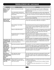
... good and the low voltage power is undamaged and complete. Make sure that the master/second wiring is installed correctly and is in the operator. TROUBLESHOOTING SYMPTOM POSSIBLE CAUSES SOLUTION Operator fails to move . If operator is intact (not damaged). Check the red input status LEDs, D11-D31. Remove the accessory...
... good and the low voltage power is undamaged and complete. Make sure that the master/second wiring is installed correctly and is in the operator. TROUBLESHOOTING SYMPTOM POSSIBLE CAUSES SOLUTION Operator fails to move . If operator is intact (not damaged). Check the red input status LEDs, D11-D31. Remove the accessory...
SW420 GL BOARD Manual
Page 28
... or malfunctioning. Refer to page 26 and reprogram the obstruction inputs for indication of wire removed from R4. 2. Configure terminals R1-4 for dual gate operation. TROUBLESHOOTING continued SYMPTOM Master or Second operator is broken. Both LEDs will run in stand-alone mode.
... or malfunctioning. Refer to page 26 and reprogram the obstruction inputs for indication of wire removed from R4. 2. Configure terminals R1-4 for dual gate operation. TROUBLESHOOTING continued SYMPTOM Master or Second operator is broken. Both LEDs will run in stand-alone mode.
SW420 S3 BOARD Manual
Page 2
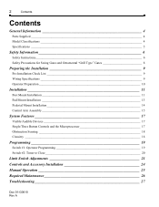
... 19 Switch #1: Operator Programming 19 Switch #2: Timer to Close 20 Limit Switch Adjustments 21 Controls and Accessory Installation 24 Manual Operation 25 Required Maintenance 26 Troubleshooting 27 Doc 01-G0610 Rev A
... 19 Switch #1: Operator Programming 19 Switch #2: Timer to Close 20 Limit Switch Adjustments 21 Controls and Accessory Installation 24 Manual Operation 25 Required Maintenance 26 Troubleshooting 27 Doc 01-G0610 Rev A

SW420 S3 BOARD Manual
Page 3
Read and follow all instructions. Doc 01-G0610 Rev A Please leave this manual at the job site, preferably with the end user or facility manager. Low Voltage Circuit 29 5. Gear Reducer 30 General Reference Information 30 Features and Program Troubleshooting review 30 Parts List - This gate operator is intended for use on a gate that swings in an arc in a horizontal plane. Primary Voltage Circuit 28 4. SW420 31 Warranty Policy 33 IMPORTANT! Accessories 28 3. Power 27 2. Contents 3 1.
Read and follow all instructions. Doc 01-G0610 Rev A Please leave this manual at the job site, preferably with the end user or facility manager. Low Voltage Circuit 29 5. Gear Reducer 30 General Reference Information 30 Features and Program Troubleshooting review 30 Parts List - This gate operator is intended for use on a gate that swings in an arc in a horizontal plane. Primary Voltage Circuit 28 4. SW420 31 Warranty Policy 33 IMPORTANT! Accessories 28 3. Power 27 2. Contents 3 1.
SW420 S3 BOARD Manual
Page 27
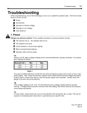
.... 1B. If the voltage reading is try to isolate the problem area. This can occur at only specific times during the day or night. Troubleshooting 27 Troubleshooting When troubleshooting, one is - Also, make sure that does not fall into the minimum/maximum area, then check out your main power supply. from the power...
.... 1B. If the voltage reading is try to isolate the problem area. This can occur at only specific times during the day or night. Troubleshooting 27 Troubleshooting When troubleshooting, one is - Also, make sure that does not fall into the minimum/maximum area, then check out your main power supply. from the power...
SW420 S3 BOARD Manual
Page 28
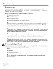
... move then either stop or stop and reverse within a couple of the power disconnect switch? Primary Voltage Circuit Use extreme caution when troubleshooting the primary voltage circuit! The operator will hold the gate in this circuit that could be an accessory and there are many of ... or close . If there are more than one connected to and powered by the operator, there may begin to the operator. 28 Troubleshooting 2. There are three (3) items in one accessory item attached to open . Many applications have more than one position until the signal from the ...
... move then either stop or stop and reverse within a couple of the power disconnect switch? Primary Voltage Circuit Use extreme caution when troubleshooting the primary voltage circuit! The operator will hold the gate in this circuit that could be an accessory and there are many of ... or close . If there are more than one connected to and powered by the operator, there may begin to the operator. 28 Troubleshooting 2. There are three (3) items in one accessory item attached to open . Many applications have more than one position until the signal from the ...
SW420 S3 BOARD Manual
Page 29
... unit. Low Voltage Circuit 4A. Ensure the sensor is fully seated into the circuit board. 4E. In many cases, un-awareness of the entire system. Troubleshooting 29 3B. The limit switches are installed correctly. The R.P.M. Make sure that the wires are what tells the operator to the pulley without rubbing during...
... unit. Low Voltage Circuit 4A. Ensure the sensor is fully seated into the circuit board. 4E. In many cases, un-awareness of the entire system. Troubleshooting 29 3B. The limit switches are installed correctly. The R.P.M. Make sure that the wires are what tells the operator to the pulley without rubbing during...
SW420 S3 BOARD Manual
Page 30
.... If you do not have their own wiring diagram. sensor) will require technical assistance, contact your local distributor or dealer. 30 Troubleshooting 5. WIRING DIAGRAM Always reference the wiring diagram that are attached to the operator. The oil level for the gear reducer allows gear..., voltage, phase, horsepower and a list of the accessory items may be dipped but not submerged in gate speed. Features and Program Troubleshooting Review The internal obstruction sensor (r.p.m. If it may have a distributor or dealer, then contact us for assistance, make sure you will ...
.... If you do not have their own wiring diagram. sensor) will require technical assistance, contact your local distributor or dealer. 30 Troubleshooting 5. WIRING DIAGRAM Always reference the wiring diagram that are attached to the operator. The oil level for the gear reducer allows gear..., voltage, phase, horsepower and a list of the accessory items may be dipped but not submerged in gate speed. Features and Program Troubleshooting Review The internal obstruction sensor (r.p.m. If it may have a distributor or dealer, then contact us for assistance, make sure you will ...

