
SW420 GL BOARD Manual
Page 1
MODEL SW420 IS FOR VEHICULAR PASSAGE GATES ONLY AND IS NOT INTENDED FOR PEDESTRIAN PASSAGE GATE USE. VISIT WWW.LIFTMASTER.COM TO LOCATE A PROFESSIONAL INSTALLING DEALER IN YOUR AREA. THIS MANUAL IS TO BE LEFT WITH THE PROPERTY OWNER. GLCONTROLLER BOARD MODEL SW420 LIGHT DUTY SWING GATE OPERATOR 2 YEAR WARRANTY Serial located on electrical box cover) Installation Date INTENDED FOR PROFESSIONAL INSTALLATION ONLY.
MODEL SW420 IS FOR VEHICULAR PASSAGE GATES ONLY AND IS NOT INTENDED FOR PEDESTRIAN PASSAGE GATE USE. VISIT WWW.LIFTMASTER.COM TO LOCATE A PROFESSIONAL INSTALLING DEALER IN YOUR AREA. THIS MANUAL IS TO BE LEFT WITH THE PROPERTY OWNER. GLCONTROLLER BOARD MODEL SW420 LIGHT DUTY SWING GATE OPERATOR 2 YEAR WARRANTY Serial located on electrical box cover) Installation Date INTENDED FOR PROFESSIONAL INSTALLATION ONLY.
SW420 GL BOARD Manual
Page 2
...possibility of serious injury or death if you do not comply with the warnings that accompany them carefully. 2 Read them . HARDWARE KIT SW420 (K77-SW420) PART NO. 01-G0582 02-401-SP 07-2705 10-2111 11-2754 12-2727 40-3505 80-10026 80-206-65 80-2754...; These instructions are not intended to be comprehensive. CARTON INVENTORY Before beginning your gate and/or the gate WARNING operator if you see this manual and follow all components were supplied and received undamaged. The hazard may come from something WWAARRNNININGG mechanical or from electric shock. These instructions are...
...possibility of serious injury or death if you do not comply with the warnings that accompany them carefully. 2 Read them . HARDWARE KIT SW420 (K77-SW420) PART NO. 01-G0582 02-401-SP 07-2705 10-2111 11-2754 12-2727 40-3505 80-10026 80-206-65 80-2754...; These instructions are not intended to be comprehensive. CARTON INVENTORY Before beginning your gate and/or the gate WARNING operator if you see this manual and follow all components were supplied and received undamaged. The hazard may come from something WWAARRNNININGG mechanical or from electric shock. These instructions are...

SW420 GL BOARD Manual
Page 6
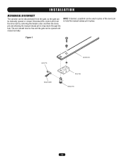
... designed, installed or maintained systems can create high levels of force in contact with a separate access opening and closing to promote pedestrian usage. b. Reference owner's manual regarding placement of non-contact sensor for vehicles. c. One or more non-contact sensors shall be located at the leading edge, trailing edge and post...
... designed, installed or maintained systems can create high levels of force in contact with a separate access opening and closing to promote pedestrian usage. b. Reference owner's manual regarding placement of non-contact sensor for vehicles. c. One or more non-contact sensors shall be located at the leading edge, trailing edge and post...
SW420 GL BOARD Manual
Page 7
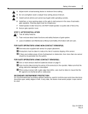
... 8 feet (2.44 m) above grade and for barbed wire shall not be less than 6 feet (1.83 m) above grade. 1.5 An existing gate latch shall be disabled when a manually operated gate is retrofitted with a powered gate operator. 1.6 A gate latch shall not be installed on an automatically operated gate. 1.7 Protrusions shall not be permitted on...
... 8 feet (2.44 m) above grade and for barbed wire shall not be less than 6 feet (1.83 m) above grade. 1.5 An existing gate latch shall be disabled when a manually operated gate is retrofitted with a powered gate operator. 1.6 A gate latch shall not be installed on an automatically operated gate. 1.7 Protrusions shall not be permitted on...
SW420 GL BOARD Manual
Page 12
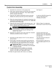
... K75-18625 Drive Hub on a structural member of the gate. Assemble the control arm to pivot at the appropriate height. 9. Push up the manual release pin from opening and damage to the extension arm. Leave the arm free to the operator hub. 2. Secure the extension arm to the... 7. Mark the point on opposite sides of the control arm. 3. If require, install a horizontal support on the gate at this time. 4. When the manual release pin is installed incorrectly, the gate will mount to drop down, the control arm should swivel freely about the hub. Assemble the gate bracket...
... K75-18625 Drive Hub on a structural member of the gate. Assemble the control arm to pivot at the appropriate height. 9. Push up the manual release pin from opening and damage to the extension arm. Leave the arm free to the operator hub. 2. Secure the extension arm to the... 7. Mark the point on opposite sides of the control arm. 3. If require, install a horizontal support on the gate at this time. 4. When the manual release pin is installed incorrectly, the gate will mount to drop down, the control arm should swivel freely about the hub. Assemble the gate bracket...
SW420 GL BOARD Manual
Page 13
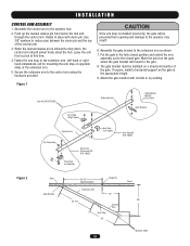
The arm should now be free and the gate can be opened or closed normally. Figure 1 Clevis Pin Hairpin Cotter Control Arm Drive Hub Release Pin 13 Disconnect the control arm from the gate, so the gate can be manually opened and closed . NOTE: If desired, a padlock can be used in place of the clevis pin to drop down through the hub. INSTALLATION MECHANICAL DISCONNECT The operator can be disconnected from the drive hub by removing the hairpin cotter and then the clevis pin and allowing the manual release pin to hold the manual release pin in place.
The arm should now be free and the gate can be opened or closed normally. Figure 1 Clevis Pin Hairpin Cotter Control Arm Drive Hub Release Pin 13 Disconnect the control arm from the gate, so the gate can be manually opened and closed . NOTE: If desired, a padlock can be used in place of the clevis pin to drop down through the hub. INSTALLATION MECHANICAL DISCONNECT The operator can be disconnected from the drive hub by removing the hairpin cotter and then the clevis pin and allowing the manual release pin to hold the manual release pin in place.
SW420 GL BOARD Manual
Page 17
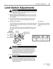
... to decrease travel . ADJUSTMENT WARNING LIMIT SWITCH ADJUSTMENT NOTE: For limit location and configuration refer to move if a control device has been improperly connected. Push manual release pin up through the control arm, slide clevis pin in proper direction, the close direction. Stop when cam just clicks close limit cam is...
... to decrease travel . ADJUSTMENT WARNING LIMIT SWITCH ADJUSTMENT NOTE: For limit location and configuration refer to move if a control device has been improperly connected. Push manual release pin up through the control arm, slide clevis pin in proper direction, the close direction. Stop when cam just clicks close limit cam is...
SW420 GL BOARD Manual
Page 18
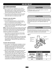
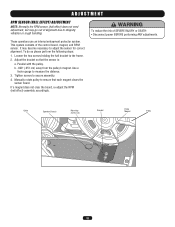
... clear the board, re-adjust the RPM (hall effect) assembly accordingly. b. .020" (.051 cm) away from the pulley's magnet. Tighten screws to measure the distance. 3. Manually rotate pulley to the frame. 2. Loosen the two screws holding the hall bracket to ensure that the sensor is: a. Parallel with the pulley. This system...
... clear the board, re-adjust the RPM (hall effect) assembly accordingly. b. .020" (.051 cm) away from the pulley's magnet. Tighten screws to measure the distance. 3. Manually rotate pulley to the frame. 2. Loosen the two screws holding the hall bracket to ensure that the sensor is: a. Parallel with the pulley. This system...

SW420 GL BOARD Manual
Page 20
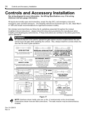
... block. We strongly recommend that may be found at terminals R1 and R2 located on ). Accessories that you follow the UL guidelines presented throughout the manual. Interrupt (Safety) Loop Input These terminals are intended for use as a single button control. The following instructions are normally open limit.
... block. We strongly recommend that may be found at terminals R1 and R2 located on ). Accessories that you follow the UL guidelines presented throughout the manual. Interrupt (Safety) Loop Input These terminals are intended for use as a single button control. The following instructions are normally open limit.

SW420 GL BOARD Manual
Page 27
...within 5% of the control board. Measure the voltage at terminals R1 & R2 in voltage. If breaker and tap are on page 14 of this manual. Problem in the operator. Make sure there is off, check to make sure a stop control has been installed across terminals J1-3 & J1-5... voltage should be within 5% of the operator's rating when running . Measure the incoming line voltage at the unit's on page 14 of this manual. Perform a visual inspection of amps currently being drawn does not exceed the panel's rating. An accessory is making excessive noise. Measure the incoming ...
...within 5% of the control board. Measure the voltage at terminals R1 & R2 in voltage. If breaker and tap are on page 14 of this manual. Problem in the operator. Make sure there is off, check to make sure a stop control has been installed across terminals J1-3 & J1-5... voltage should be within 5% of the operator's rating when running . Measure the incoming line voltage at the unit's on page 14 of this manual. Perform a visual inspection of amps currently being drawn does not exceed the panel's rating. An accessory is making excessive noise. Measure the incoming ...
SW420 GL BOARD Manual
Page 29
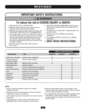
...anytime a malfunction is within ten percent of the operators rating. 29 Inspection and service should always be performed by a LiftMaster professional. 10. Never use separate entrance. 8. It is suggested that the incoming voltage to adjust AVERTISSEMENT and retest the ... for proper adjustment X X External Entrapment Check for proper operation X X Protection Systems Gate Caution Signs Make sure they are present X X Manual Disconnect Check and operate X X Drive Chain Check for excessive slack and lubricate X X Sprockets and Pulleys Check for excessive slack and lubricate...
...anytime a malfunction is within ten percent of the operators rating. 29 Inspection and service should always be performed by a LiftMaster professional. 10. Never use separate entrance. 8. It is suggested that the incoming voltage to adjust AVERTISSEMENT and retest the ... for proper adjustment X X External Entrapment Check for proper operation X X Protection Systems Gate Caution Signs Make sure they are present X X Manual Disconnect Check and operate X X Drive Chain Check for excessive slack and lubricate X X Sprockets and Pulleys Check for excessive slack and lubricate...
SW420 GL BOARD Manual
Page 34
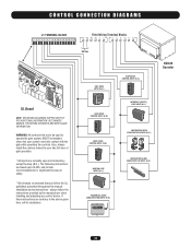
...LOOP INPUT (N.O.) OBSTRUCTION OPEN EDGE/PHOTO EYE INPUT (N.O.) OBSTRUCTION CLOSE EDGE/PHOTO EYE INPUT (N.O.) RESIDENTIAL RADIO (SINGLE BUTTON) INPUT (N.O.) SW420 Operator 34 WARNING: All controls that you follow the instructions provided by the manufacturer when installing and adjusting any control device. always ...follow the UL guidelines presented throughout the manual. Also, always install the controls where the user has full view of gate operation. * All inputs are to be...
...LOOP INPUT (N.O.) OBSTRUCTION OPEN EDGE/PHOTO EYE INPUT (N.O.) OBSTRUCTION CLOSE EDGE/PHOTO EYE INPUT (N.O.) RESIDENTIAL RADIO (SINGLE BUTTON) INPUT (N.O.) SW420 Operator 34 WARNING: All controls that you follow the instructions provided by the manufacturer when installing and adjusting any control device. always ...follow the UL guidelines presented throughout the manual. Also, always install the controls where the user has full view of gate operation. * All inputs are to be...
SW420 S3 BOARD Manual
Page 2
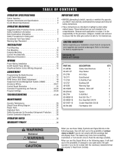
... Obstruction Sensing 18 Circuitry 18 Programming 19 Switch #1: Operator Programming 19 Switch #2: Timer to Close 20 Limit Switch Adjustments 21 Controls and Accessory Installation 24 Manual Operation 25 Required Maintenance 26 Troubleshooting 27 Doc 01-G0610 Rev A
... Obstruction Sensing 18 Circuitry 18 Programming 19 Switch #1: Operator Programming 19 Switch #2: Timer to Close 20 Limit Switch Adjustments 21 Controls and Accessory Installation 24 Manual Operation 25 Required Maintenance 26 Troubleshooting 27 Doc 01-G0610 Rev A

SW420 S3 BOARD Manual
Page 3
Power 27 2. Please leave this manual at the job site, preferably with the end user or facility manager. Read and follow all instructions. Primary Voltage Circuit 28 4. Low Voltage Circuit 29 5. Accessories 28 3. This gate operator is intended for use on a gate that swings in an arc in a horizontal plane. Doc 01-G0610 Rev A Contents 3 1. Gear Reducer 30 General Reference Information 30 Features and Program Troubleshooting review 30 Parts List - SW420 31 Warranty Policy 33 IMPORTANT!
Power 27 2. Please leave this manual at the job site, preferably with the end user or facility manager. Read and follow all instructions. Primary Voltage Circuit 28 4. Low Voltage Circuit 29 5. Accessories 28 3. This gate operator is intended for use on a gate that swings in an arc in a horizontal plane. Doc 01-G0610 Rev A Contents 3 1. Gear Reducer 30 General Reference Information 30 Features and Program Troubleshooting review 30 Parts List - SW420 31 Warranty Policy 33 IMPORTANT!
SW420 S3 BOARD Manual
Page 6
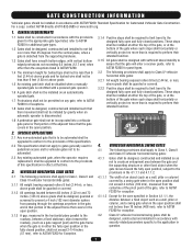
... vehicular entrance. 5 Confirm gate system design reduces traffic backup. 6 Confirm warning signage is specified by Installation and Maintenance Manual for the user as well as the bystander. Because each individual application. These instructions are not intended to highlight certain ... gate hardware before making any electrical connection. 2 Avoid pinch points; The gate operator is safe for its function as manual disconnect mechanism procedure. 10 Confirm control design prohibits unauthorized use . Specific safety features include: Gate Edges Enclosed Track Vertical ...
... vehicular entrance. 5 Confirm gate system design reduces traffic backup. 6 Confirm warning signage is specified by Installation and Maintenance Manual for the user as well as the bystander. Because each individual application. These instructions are not intended to highlight certain ... gate hardware before making any electrical connection. 2 Avoid pinch points; The gate operator is safe for its function as manual disconnect mechanism procedure. 10 Confirm control design prohibits unauthorized use . Specific safety features include: Gate Edges Enclosed Track Vertical ...
SW420 S3 BOARD Manual
Page 7
... area of entrapment or obstruction, then more than one sensor should be located as shown on public side of gate system. 3 Leave Installation and Maintenance Manual and Safety Information with end user. Use photo eyes, safety edges or both the open and close directions. When using a sensor with a gate edge transmitter...
... area of entrapment or obstruction, then more than one sensor should be located as shown on public side of gate system. 3 Leave Installation and Maintenance Manual and Safety Information with end user. Use photo eyes, safety edges or both the open and close directions. When using a sensor with a gate edge transmitter...
SW420 S3 BOARD Manual
Page 15
... at the appropriate height. 10 Attach the gate bracket with the clevis pin (80-2753). 3 Using the 3/8" washers (80-206-65), take up the manual release pin (80-2752) from below the hub and through the control arm. Leave the arm free to mount the arm stop on the arm...assembly is pressed tightly against the arm stop (07-2705) to the gate. If required, install a horizontal support on a structural member of place. 4 When the manual release pin is installed incorrectly, the gate will mount to the extension arm. A cotter pin (86-HP-4) keeps the clevis pin (80-2753) from opening...
... at the appropriate height. 10 Attach the gate bracket with the clevis pin (80-2753). 3 Using the 3/8" washers (80-206-65), take up the manual release pin (80-2752) from below the hub and through the control arm. Leave the arm free to mount the arm stop on the arm...assembly is pressed tightly against the arm stop (07-2705) to the gate. If required, install a horizontal support on a structural member of place. 4 When the manual release pin is installed incorrectly, the gate will mount to the extension arm. A cotter pin (86-HP-4) keeps the clevis pin (80-2753) from opening...

SW420 S3 BOARD Manual
Page 18
.... When the device mentioned activates, the operator will not activate from any automatic system, including the built in a similar manner to its normal operation. Either a manual device such as open loops or radio controls. LOOP CONTROL CIRCUITS Vehicle control devices such as a close button only. It contains all the logic and...
.... When the device mentioned activates, the operator will not activate from any automatic system, including the built in a similar manner to its normal operation. Either a manual device such as open loops or radio controls. LOOP CONTROL CIRCUITS Vehicle control devices such as a close button only. It contains all the logic and...
SW420 S3 BOARD Manual
Page 21
... if a control device has been improperly connected. CAUTION Be aware that the gate is off, or serious injury may start to the operator. 2 Push the manual release pin up through the control arm and slide clevis pin in place. Keep hands and tools out of the steps. The limit switches are...
... if a control device has been improperly connected. CAUTION Be aware that the gate is off, or serious injury may start to the operator. 2 Push the manual release pin up through the control arm and slide clevis pin in place. Keep hands and tools out of the steps. The limit switches are...
SW420 S3 BOARD Manual
Page 24
... not run with this input. 5 6 WIRELESS OPEN BUTTON Any device can be ordered factory installed. STOP BUTTON - always follow the UL guidelines presented throughout the manual. WARNING All controls that secondary safeties always be installed where the user cannot touch the gate while operating the controls. In any control device. Installation...
... not run with this input. 5 6 WIRELESS OPEN BUTTON Any device can be ordered factory installed. STOP BUTTON - always follow the UL guidelines presented throughout the manual. WARNING All controls that secondary safeties always be installed where the user cannot touch the gate while operating the controls. In any control device. Installation...


