DJ Locksensor Mechanical Manual
Page 1
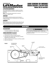
... of reduction chain Final Reduction Chain Mounting Screws Lock Sensor Assembly Lock Sensor Switch (held to operator BEFORE adjusting Lock Sensor. Repeat fine adjustments. LOCK SENSOR (D1 WIRING) WIRING DIAGRAM & INSTRUCTIONS Model: DH, DJ and DH/J ADJUSTMENT FINE ADJUSTMENT • To increase opening force, tighten wing nut. • To decrease opening force...
... of reduction chain Final Reduction Chain Mounting Screws Lock Sensor Assembly Lock Sensor Switch (held to operator BEFORE adjusting Lock Sensor. Repeat fine adjustments. LOCK SENSOR (D1 WIRING) WIRING DIAGRAM & INSTRUCTIONS Model: DH, DJ and DH/J ADJUSTMENT FINE ADJUSTMENT • To increase opening force, tighten wing nut. • To decrease opening force...
DJ Locksensor Mechanical Manual
Page 4
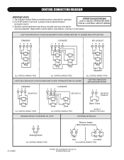
ATTENTION ELECTRICIAN: USE 16 GAUGE OR HEAVIER WIRE FOR ALL CONTROL CIRCUIT WIRING. 3. All Rights Reserved Auxiliary control equipment may be connected for operation. 2. The 3-Button Control Station provided must be placed between terminals 3 and 4. If a STOP button is not used, a jumper must be any normally open two wire ...
ATTENTION ELECTRICIAN: USE 16 GAUGE OR HEAVIER WIRE FOR ALL CONTROL CIRCUIT WIRING. 3. All Rights Reserved Auxiliary control equipment may be connected for operation. 2. The 3-Button Control Station provided must be placed between terminals 3 and 4. If a STOP button is not used, a jumper must be any normally open two wire ...
DJ LOGIC 2 ADDENDUM Manual
Page 1
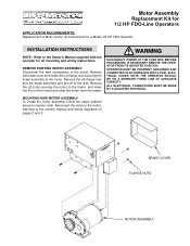
... to the side. Remove the brake cover and locate the (4) flange nuts securing the brake assembly to the Owner's Manual supplied with the operator for a Model 1/2 HP FDO Operator. INSTALLATION INSTRUCWTIOANRSNING WARNING NOTE: Refer to the motor. DISCONNECT POWER AT THE FUSE BOX BEFORE PROCEEDING. NOTE: THE... OPERATOR SHOULD BE ON A SEPARATE FUSED LINE OF ADEQUATE WARNING CAPACITY. BRAKE COVER FLANGE NUTS MOTOR ASSEMBLY Remove the (2) bolts securing the motor to ...
... to the side. Remove the brake cover and locate the (4) flange nuts securing the brake assembly to the Owner's Manual supplied with the operator for a Model 1/2 HP FDO Operator. INSTALLATION INSTRUCWTIOANRSNING WARNING NOTE: Refer to the motor. DISCONNECT POWER AT THE FUSE BOX BEFORE PROCEEDING. NOTE: THE... OPERATOR SHOULD BE ON A SEPARATE FUSED LINE OF ADEQUATE WARNING CAPACITY. BRAKE COVER FLANGE NUTS MOTOR ASSEMBLY Remove the (2) bolts securing the motor to ...
DJ Locksensor Addendum L3 Manual
Page 1
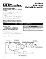
... SSennssoorrAAsssememblbyly MMouounntitninggSSccrreewwss LLoocckkSSenesnosroSrwSiwtcihtch AVERTISSEMENT ((hheeldldtotonnoormrmalalyllcylocsloeds)e.d). ADDENDUM LOCK SENSOR Models DH, DJ, and DHJ NOTE: Refer to secure lock sensor position. 5. COURSE ADJUSTMENT (IF REQUIRED) 1. Fully tension final reduction chain and rotate lock sensor until it shuts off (to models H and J Logic operators. FiFnianlalRReedduucction CChhaainin CChhaaininIdIdleler rSSprporcokcekt et mmuusstt eennggaaggeetotpopsidseide ooff rreedduucctitoionncchhaiani.n. Press...
... SSennssoorrAAsssememblbyly MMouounntitninggSSccrreewwss LLoocckkSSenesnosroSrwSiwtcihtch AVERTISSEMENT ((hheeldldtotonnoormrmalalyllcylocsloeds)e.d). ADDENDUM LOCK SENSOR Models DH, DJ, and DHJ NOTE: Refer to secure lock sensor position. 5. COURSE ADJUSTMENT (IF REQUIRED) 1. Fully tension final reduction chain and rotate lock sensor until it shuts off (to models H and J Logic operators. FiFnianlalRReedduucction CChhaainin CChhaaininIdIdleler rSSprporcokcekt et mmuusstt eennggaaggeetotpopsidseide ooff rreedduucctitoionncchhaiani.n. Press...


