DJ Locksensor Mechanical Manual
Page 1
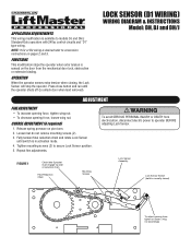
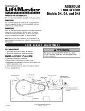
... reduction chain and rotate Lock Sensor until the operator shuts off (to models DJ and DH/J Standard-Duty operators with 24Vac control circuits and "D1" type wiring. OPERATION When the operator senses extra tension when closing, the Lock Sensor will stop the operator. Tighten mounting screws (2) to normally closed) To adjust opening force, loosen wing nut. Release spring pressure on pages 2 and 3. To avoid SERIOUS PERSONAL INJURY or DEATH from the mechanical door lock, obstruction or extensive binding. Press close button and...
... reduction chain and rotate Lock Sensor until the operator shuts off (to models DJ and DH/J Standard-Duty operators with 24Vac control circuits and "D1" type wiring. OPERATION When the operator senses extra tension when closing, the Lock Sensor will stop the operator. Tighten mounting screws (2) to normally closed) To adjust opening force, loosen wing nut. Release spring pressure on pages 2 and 3. To avoid SERIOUS PERSONAL INJURY or DEATH from the mechanical door lock, obstruction or extensive binding. Press close button and...
DJ Locksensor Mechanical Manual
Page 2
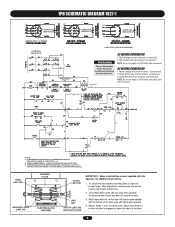
NOTE: Be sure to supply a STOP button and safety edge after conversion. AUXILIARY CLOSE 2 B2 WIRING CONVERSION 1. OPEN LIMIT SW. Move Yellow wire from terminal 1 to terminal 3. 3. Move Yellow wire from terminal 1 to terminal 3. ELECTRICAL BOX END VIEW LIMIT NUT SAFETY LIMIT SW. Move Red wire from terminal 7 to terminal 3. DEPRESS PLATE CLOSE LIMIT SW. AUXILIARY OPEN LIMIT SW. Move Orange wire from terminal 2 to terminal 3. 2. 1PH SCHEMATIC DIAGRAM 1827-1 BK BL/BK GY...
NOTE: Be sure to supply a STOP button and safety edge after conversion. AUXILIARY CLOSE 2 B2 WIRING CONVERSION 1. OPEN LIMIT SW. Move Yellow wire from terminal 1 to terminal 3. 3. Move Yellow wire from terminal 1 to terminal 3. ELECTRICAL BOX END VIEW LIMIT NUT SAFETY LIMIT SW. Move Red wire from terminal 7 to terminal 3. DEPRESS PLATE CLOSE LIMIT SW. AUXILIARY OPEN LIMIT SW. Move Orange wire from terminal 2 to terminal 3. 2. 1PH SCHEMATIC DIAGRAM 1827-1 BK BL/BK GY...

DJ Locksensor Mechanical Manual
Page 3
... VOLT - 3 PHASE MOTOR CONNECTION * MOTOR O/L LEAD COLOR BROWN C2 WIRING CONVERSION 1. Move Red wire from terminal 1 to supply a STOP button after conversion. DEPRESS PLATE CLOSE LIMIT SW. NOTE: Be sure to terminal 3. OPEN LIMIT SW. AUXILIARY CLOSE 3 NOTES: 1) TO REVERSE MOTOR DIRECTION: INTERCHANGE PURPLE & GRAY MOTOR LEADS AT CONTACTOR 1 & 3. 2) TRANSFORMER PRIMARY & RELAY VOLTAGE SAME AS LINE VOLTAGE. 3) THREE PHASE UNITS MAY BE EQUIPPED WITH AN INTERNAL PILOT DUTY THERMAL OVERLOAD...
... VOLT - 3 PHASE MOTOR CONNECTION * MOTOR O/L LEAD COLOR BROWN C2 WIRING CONVERSION 1. Move Red wire from terminal 1 to supply a STOP button after conversion. DEPRESS PLATE CLOSE LIMIT SW. NOTE: Be sure to terminal 3. OPEN LIMIT SW. AUXILIARY CLOSE 3 NOTES: 1) TO REVERSE MOTOR DIRECTION: INTERCHANGE PURPLE & GRAY MOTOR LEADS AT CONTACTOR 1 & 3. 2) TRANSFORMER PRIMARY & RELAY VOLTAGE SAME AS LINE VOLTAGE. 3) THREE PHASE UNITS MAY BE EQUIPPED WITH AN INTERNAL PILOT DUTY THERMAL OVERLOAD...
DJ Locksensor Mechanical Manual
Page 4
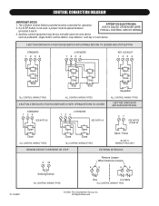
..., The Chamberlain Group, Inc. CONTROL CONNECTION DIAGRAM IMPORTANT NOTES: 1. ATTENTION ELECTRICIAN: USE 16 GAUGE OR HEAVIER WIRE FOR ALL CONTROL CIRCUIT WIRING. 3. Auxiliary control equipment may be any normally open two wire device such as pullswitch, single button control station, loop detector, card key or such device. 3 BUTTON STATION OR 3 POSITION KEYSWITCH WITH SPRING RETURN TO CENTER AND STOP BUTTON STANDARD 1234 2 OR MORE 1234 KEY LOCKOUT 1234 Open Close Stop Open Close Stop Open Close Stop Open Close Stop Keyswitch ALL CONTROL WIRING TYPES ALL CONTROL WIRING TYPES...
..., The Chamberlain Group, Inc. CONTROL CONNECTION DIAGRAM IMPORTANT NOTES: 1. ATTENTION ELECTRICIAN: USE 16 GAUGE OR HEAVIER WIRE FOR ALL CONTROL CIRCUIT WIRING. 3. Auxiliary control equipment may be any normally open two wire device such as pullswitch, single button control station, loop detector, card key or such device. 3 BUTTON STATION OR 3 POSITION KEYSWITCH WITH SPRING RETURN TO CENTER AND STOP BUTTON STANDARD 1234 2 OR MORE 1234 KEY LOCKOUT 1234 Open Close Stop Open Close Stop Open Close Stop Open Close Stop Keyswitch ALL CONTROL WIRING TYPES ALL CONTROL WIRING TYPES...
DJ LOGIC 2 ADDENDUM Manual
Page 1
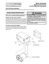
... CAUTION and the break assembly and set off to the owners manual and wiring diagrams on pages 2 and 3. BRAKE COVER FLANGE NUTS MOTOR ASSEMBLY OPERATOR MUST BE PROPERLY GROUNDED AND CONNECTED IN ACCORDANCE WITH LOCAL ELECTRICAL CODES. Reconnect the wires to the motor, referring to the side. ALL ELECTRICAL CONNECTIONS MUST BE MADE BY A QUALIFIED INDIVIDUAL. DISCONNECT POWER AT THE FUSE BOX BEFORE PROCEEDING. MOUNTING NEW MOTOR ASSEMBLY: To install the motor assembly, follow the steps outlined...
... CAUTION and the break assembly and set off to the owners manual and wiring diagrams on pages 2 and 3. BRAKE COVER FLANGE NUTS MOTOR ASSEMBLY OPERATOR MUST BE PROPERLY GROUNDED AND CONNECTED IN ACCORDANCE WITH LOCAL ELECTRICAL CODES. Reconnect the wires to the motor, referring to the side. ALL ELECTRICAL CONNECTIONS MUST BE MADE BY A QUALIFIED INDIVIDUAL. DISCONNECT POWER AT THE FUSE BOX BEFORE PROCEEDING. MOUNTING NEW MOTOR ASSEMBLY: To install the motor assembly, follow the steps outlined...
DJ LOGIC 2 ADDENDUM Manual
Page 2
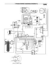
1 PHASE WIRING DIAGRAM (FDOB5011) 1846 MOTOR CONNECTIONS
1 PHASE WIRING DIAGRAM (FDOB5011) 1846 MOTOR CONNECTIONS

DJ LOGIC 2 ADDENDUM Manual
Page 3
1 PHASE WIRING DIAGRAM (FDOA5011) 1845 MOTOR CONNECTIONS
1 PHASE WIRING DIAGRAM (FDOA5011) 1845 MOTOR CONNECTIONS

DJ LOGIC 2 ADDENDUM Manual
Page 4
01-17365C © 2000, The Chamberlain Group, Inc. All Rights Reserved MADE IN MEXICO
01-17365C © 2000, The Chamberlain Group, Inc. All Rights Reserved MADE IN MEXICO
DJ Locksensor Addendum L3 Manual
Page 1
...)e.d). Release spring pressure on the door from the close button and run the operator until switch is removed). OPERATION When the lock sensor senses an excessive load while running when extra tension is available to owner's manual provided with operator. All Rights Reserved Keep hands CAUTION CLEAR of sprockets, chains, and other installation instructions refer to models H and J Logic operators. ATTENTION TTooadajdujsutsotpoepneinnginfogrcfoertcigehten otriglohotseennoardljousotsmeenntaodnjuwstinmgennutt aoccnowrdiinnglyn.ut accordingly. 01-31376C © 2010, The Chamberlain...
...)e.d). Release spring pressure on the door from the close button and run the operator until switch is removed). OPERATION When the lock sensor senses an excessive load while running when extra tension is available to owner's manual provided with operator. All Rights Reserved Keep hands CAUTION CLEAR of sprockets, chains, and other installation instructions refer to models H and J Logic operators. ATTENTION TTooadajdujsutsotpoepneinnginfogrcfoertcigehten otriglohotseennoardljousotsmeenntaodnjuwstinmgennutt aoccnowrdiinnglyn.ut accordingly. 01-31376C © 2010, The Chamberlain...


