BG790 Manual
Page 1
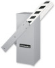
OWNER'S MANUAL MODELS BG770 & BG790 VEHICULAR BARRIER GATE OPERATOR MODELS BG770 AND BG790 ARE FOR VEHICULAR PASSAGE GATES ONLY AND ARE NOT INTENDED FOR PEDESTRIAN PASSAGE GATE USE
OWNER'S MANUAL MODELS BG770 & BG790 VEHICULAR BARRIER GATE OPERATOR MODELS BG770 AND BG790 ARE FOR VEHICULAR PASSAGE GATES ONLY AND ARE NOT INTENDED FOR PEDESTRIAN PASSAGE GATE USE
BG790 Manual
Page 2
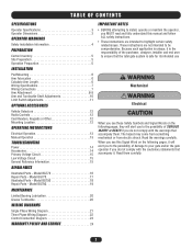
Model BG790 19 MAINTENANCE Limited Bearing Lubrication 20 Grease Turnbuckle 20 WIRING DIAGRAMS Single Phase Wiring Diagram 21 Three Phase Wiring Diagram 22 Control Connection ...you see this manual and follow ALL safety instructions. • These instructions are not intended to highlight certain safety related issues. Model BG790 18 Repair Parts - Read them . Model BG770 16 Repair Parts - Model BG770 17 Illustrated Parts - TABLE OF CONTENTS SPECIFICATIONS Operator Specifications 3 Operator Dimensions 3 OPERATOR WARNINGS Safety Installation Information 4 PREPARATION Carton...
Model BG790 19 MAINTENANCE Limited Bearing Lubrication 20 Grease Turnbuckle 20 WIRING DIAGRAMS Single Phase Wiring Diagram 21 Three Phase Wiring Diagram 22 Control Connection ...you see this manual and follow ALL safety instructions. • These instructions are not intended to highlight certain safety related issues. Model BG790 18 Repair Parts - Read them . Model BG770 16 Repair Parts - Model BG770 17 Illustrated Parts - TABLE OF CONTENTS SPECIFICATIONS Operator Specifications 3 Operator Dimensions 3 OPERATOR WARNINGS Safety Installation Information 4 PREPARATION Carton...
BG790 Manual
Page 3
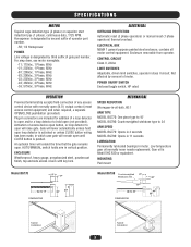
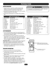
... . Gear oil is designated by second suffix of access device open button, or loop detector to 24' ARM SPEED MODEL BG770: Opens in 4 seconds MODEL BG790: Opens in 11 seconds LUBRICATION Permanently lubricated bearings in which case gate will extend the time that the gate remains open... until CLOSE button is pushed. Plug-in -oil-bath, 60:1 ARM TYPE MODEL BG770: One piece type to 15' MODEL BG790: Counterweighted wishbone type to open (N.O.) output contact (most access control equipment) and when required, a separate OPEN/CLOSE pushbutton ...
... . Gear oil is designated by second suffix of access device open button, or loop detector to 24' ARM SPEED MODEL BG770: Opens in 4 seconds MODEL BG790: Opens in 11 seconds LUBRICATION Permanently lubricated bearings in which case gate will extend the time that the gate remains open... until CLOSE button is pushed. Plug-in -oil-bath, 60:1 ARM TYPE MODEL BG770: One piece type to 15' MODEL BG790: Counterweighted wishbone type to open (N.O.) output contact (most access control equipment) and when required, a separate OPEN/CLOSE pushbutton ...
BG790 Manual
Page 5
...the gate. Verify that selected gate location has required clearance for connection of factory-provided optional radio controls (see Optional Accessories on model BG790). MODEL BG790 PACKING LIST PART NUMBER DESCRIPTION QTY 02-102 Open/Close Push Button 1 07-8007 Arm Hub 2 10-8055 Counter Weight Clamp... the position of SEVERE INJURY or DEATH, disconnect power BEFORE performing ANY adjustments. Check that the available power is packed separately. MODEL BG770 PACKING LIST PART NUMBER DESCRIPTION QTY 02-102 Open/Close Push Button 1 07-8007 Gate Arm Hub 1 10-8007M Gate...
...the gate. Verify that selected gate location has required clearance for connection of factory-provided optional radio controls (see Optional Accessories on model BG790). MODEL BG790 PACKING LIST PART NUMBER DESCRIPTION QTY 02-102 Open/Close Push Button 1 07-8007 Arm Hub 2 10-8055 Counter Weight Clamp... the position of SEVERE INJURY or DEATH, disconnect power BEFORE performing ANY adjustments. Check that the available power is packed separately. MODEL BG770 PACKING LIST PART NUMBER DESCRIPTION QTY 02-102 Open/Close Push Button 1 07-8007 Gate Arm Hub 1 10-8007M Gate...
BG790 Manual
Page 6
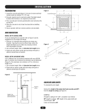
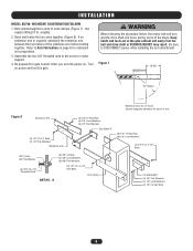
... Conduit Entry Area 14" conduit inside the hatched 14" x 13" area. 2. Finish arm with exterior grade paint and stripe with every BG790 gate. The maximum arm extension is as required. Refer to ceiling is 8'3" (99"), calculation is 8' for pad and conduit. EXAMPLE: ...to desired length. Refer to ceiling (see Figure 5). INSTALLATION PAD MOUNTING Figure 2 20" 1. Tapering the wood as required by local codes. 3. Figure 3 MODEL BG790 (WISHBONE ARM) 5-12" A 24' wishbone arm is desired, the extension may be level and above the ground line. 14-1/2" 4. If a shorter arm...
... Conduit Entry Area 14" conduit inside the hatched 14" x 13" area. 2. Finish arm with exterior grade paint and stripe with every BG790 gate. The maximum arm extension is as required. Refer to ceiling is 8'3" (99"), calculation is 8' for pad and conduit. EXAMPLE: ...to desired length. Refer to ceiling (see Figure 5). INSTALLATION PAD MOUNTING Figure 2 20" 1. Tapering the wood as required by local codes. 3. Figure 3 MODEL BG790 (WISHBONE ARM) 5-12" A 24' wishbone arm is desired, the extension may be level and above the ground line. 14-1/2" 4. If a shorter arm...
BG790 Manual
Page 7
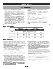
... will mount the control station outdoors, replace the standard station supplied with the operator with local electrical codes. You may result. 5. MODEL BG790: Hang electrical enclosure on the two screws provided on a dedicated circuit and well protected. WIRING SPECIFICATIONS AWG 6 8 10 12 SINGLE...at the fuse box BEFORE proceeding. If the control wire is provided as shown on the wiring diagram supplied with every BG770 and BG790 barrier gate. If you are complete, mount the electrical enclosure to the Optional Accessories section on electrical cabinet cover. 3. Upon ...
... will mount the control station outdoors, replace the standard station supplied with the operator with local electrical codes. You may result. 5. MODEL BG790: Hang electrical enclosure on the two screws provided on a dedicated circuit and well protected. WIRING SPECIFICATIONS AWG 6 8 10 12 SINGLE...at the fuse box BEFORE proceeding. If the control wire is provided as shown on the wiring diagram supplied with every BG770 and BG790 barrier gate. If you are complete, mount the electrical enclosure to the Optional Accessories section on electrical cabinet cover. 3. Upon ...
BG790 Manual
Page 8
... B Threaded Rod Hex Bolt Flat Washer DETAIL B (2) Flat Washers Hex Nut Hex Nut Hex Nut Flat Washer Threaded Spacer Flat Washer Flat Washer Hex Bolt 8 MODEL BG770: OPTIONAL ARM Attach arm to DISCONNECT power while installing the arm attachment...
... B Threaded Rod Hex Bolt Flat Washer DETAIL B (2) Flat Washers Hex Nut Hex Nut Hex Nut Flat Washer Threaded Spacer Flat Washer Flat Washer Hex Bolt 8 MODEL BG770: OPTIONAL ARM Attach arm to DISCONNECT power while installing the arm attachment...
BG790 Manual
Page 9
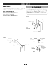
... the arm attachment. Be sure to the arms for gate to start when you turn and the drive shaft will turn the power on. INSTALLATION MODEL BG790: WISHBONE COUNTERWEIGHTED ARM 1. weights. 2. If an extension arm is required, sandwich the extension arm between the two halves of the gate cabinet and away from...
... the arm attachment. Be sure to the arms for gate to start when you turn and the drive shaft will turn the power on. INSTALLATION MODEL BG790: WISHBONE COUNTERWEIGHTED ARM 1. weights. 2. If an extension arm is required, sandwich the extension arm between the two halves of the gate cabinet and away from...
BG790 Manual
Page 10
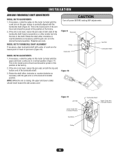
MODEL BG770 TURNBUCKLE SHAFT ALIGNMENT If necessary, align turnbuckle shaft with the turnbuckle shaft (Figure 9). NOTE: While the arm ... the lowest point of travel and should travel of travel toward the side access cover. This is in the desired horizontal position. MODEL BG790 ADJUSTMENTS 1. If the arm is perfectly aligned with center of crank arm for lowest point of pivot arm (Figure 10). CAUTION ...(Figure 11). If necessary, rotate the pulley on both ends of the turnbuckle shaft. 3. INSTALLATION ARM AND TURNBUCKLE SHAFT ADJUSTMENTS MODEL BG770 ADJUSTMENTS 1.
MODEL BG770 TURNBUCKLE SHAFT ALIGNMENT If necessary, align turnbuckle shaft with the turnbuckle shaft (Figure 9). NOTE: While the arm ... the lowest point of travel and should travel of travel toward the side access cover. This is in the desired horizontal position. MODEL BG790 ADJUSTMENTS 1. If the arm is perfectly aligned with center of crank arm for lowest point of pivot arm (Figure 10). CAUTION ...(Figure 11). If necessary, rotate the pulley on both ends of the turnbuckle shaft. 3. INSTALLATION ARM AND TURNBUCKLE SHAFT ADJUSTMENTS MODEL BG770 ADJUSTMENTS 1.
BG790 Manual
Page 12
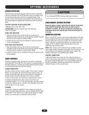
... and BG790. Use a wiring method that will need a separate power source. Connect the detector(s) according to Terminals #3 and #6 on the wiring diagram. FACTORY SUPPLIED PLUG-IN DETECTORS LiftMaster P/N 71-416-7NH = 24V PLEASE NOTE: Previous models used and extended through the side of the cabinet. If... on the control wiring terminal strip. If the receiver requires 115Vac or other power, you are unsure of or unfamiliar with model BG770 and BG790. Plug the harness into the connector marked "OPEN." 2. MOUNTING LOCATION Mount or install the access control device within sight of...
... and BG790. Use a wiring method that will need a separate power source. Connect the detector(s) according to Terminals #3 and #6 on the wiring diagram. FACTORY SUPPLIED PLUG-IN DETECTORS LiftMaster P/N 71-416-7NH = 24V PLEASE NOTE: Previous models used and extended through the side of the cabinet. If... on the control wiring terminal strip. If the receiver requires 115Vac or other power, you are unsure of or unfamiliar with model BG770 and BG790. Plug the harness into the connector marked "OPEN." 2. MOUNTING LOCATION Mount or install the access control device within sight of...
BG790 Manual
Page 15
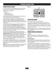
...press down on all of transformer for close position. If you cannot correct the problem or if you feel you have the gate operator model number, voltage, phase, horsepower and a list of the contactor. Please when calling for it be replaced. TROUBLESHOOTING PRIMARY VOLTAGE CIRCUIT Use... THE GATE Double check the gate and its related hardware. If you should get NO continuity; Did the operator run in the controller (Model BG770 uses a manual reset overload). Disconnect Power! Using a volt-ohmmeter, take continuity readings across the contacts of the contactor. The secondary...
...press down on all of transformer for close position. If you cannot correct the problem or if you feel you have the gate operator model number, voltage, phase, horsepower and a list of the contactor. Please when calling for it be replaced. TROUBLESHOOTING PRIMARY VOLTAGE CIRCUIT Use... THE GATE Double check the gate and its related hardware. If you should get NO continuity; Did the operator run in the controller (Model BG770 uses a manual reset overload). Disconnect Power! Using a volt-ohmmeter, take continuity readings across the contacts of the contactor. The secondary...
BG790 Manual
Page 17
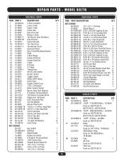
MODEL BG770 INDIVIDUAL PARTS ITEM PART # 1 03-8024-K 2 07-8003 3 07-8004 4 07-8005 5 07-8007 6 10-3522 7 10-8001-T 8 10-8007-M 9 10-8014 10 10-... 12 Used on: BG770-50-53 4 47 24-XXX-X Relay 1 24-115-1 115Vac Relay 1 Used on: All 115Vac, 10 Models 1 24-230-5 208/230Vac Relay 14 Used on: All 208/230Vac, 1 10 Models 1 48 25-XXXX Fuse 1 1 25-2006 6A Fuse 8 1 2 25-2010 Used on: BG770-50-21 10A Fuse 1 Used on...
MODEL BG770 INDIVIDUAL PARTS ITEM PART # 1 03-8024-K 2 07-8003 3 07-8004 4 07-8005 5 07-8007 6 10-3522 7 10-8001-T 8 10-8007-M 9 10-8014 10 10-... 12 Used on: BG770-50-53 4 47 24-XXX-X Relay 1 24-115-1 115Vac Relay 1 Used on: All 115Vac, 10 Models 1 24-230-5 208/230Vac Relay 14 Used on: All 208/230Vac, 1 10 Models 1 48 25-XXXX Fuse 1 1 25-2006 6A Fuse 8 1 2 25-2010 Used on: BG770-50-21 10A Fuse 1 Used on...
BG790 Manual
Page 18
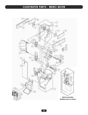
MODEL BG790 12 34 33 2 7 14 2 33 40 15 3 42 40 16 8 37 32 9 6 24 1 22 31 26 32 27 48 41 4 14 13 43 44 5 14 30 36 10 17 18 20 19 21 34 12 28 29 44 25 45 39 23 38 45 44 35 46 14 47 11 49 Operator Assembly (Wishbone Arm not shown) 18 ILLUSTRATED PARTS -
MODEL BG790 12 34 33 2 7 14 2 33 40 15 3 42 40 16 8 37 32 9 6 24 1 22 31 26 32 27 48 41 4 14 13 43 44 5 14 30 36 10 17 18 20 19 21 34 12 28 29 44 25 45 39 23 38 45 44 35 46 14 47 11 49 Operator Assembly (Wishbone Arm not shown) 18 ILLUSTRATED PARTS -
BG790 Manual
Page 19
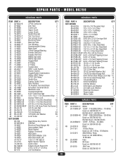
MODEL BG790 INDIVIDUAL PARTS INDIVIDUAL PARTS ITEM PART # 1 03-8024-K 2 07-8007 3 07-8058 4 07-8063 5 07-8064 6 10-8014 ...230/460Vac - 30-60Hz Used on: BG790-50-23, BG790-50-43, BG790-50-83 20-3050M-5 1/2HP - 575Vac - 30-60Hz Used on: BG790-50-53 48 24-XXX-X Relay 1 24-115-1 115Vac Relay Used on: All 115Vac, 10 Models 24-230-5 208/230Vac Relay Used on:... All 208/230Vac, 10 Models 49 25-XXXX Fuse 1 25-2006 6A Fuse Used on: BG790-50-21 25-...
MODEL BG790 INDIVIDUAL PARTS INDIVIDUAL PARTS ITEM PART # 1 03-8024-K 2 07-8007 3 07-8058 4 07-8063 5 07-8064 6 10-8014 ...230/460Vac - 30-60Hz Used on: BG790-50-23, BG790-50-43, BG790-50-83 20-3050M-5 1/2HP - 575Vac - 30-60Hz Used on: BG790-50-53 48 24-XXX-X Relay 1 24-115-1 115Vac Relay Used on: All 115Vac, 10 Models 24-230-5 208/230Vac Relay Used on:... All 208/230Vac, 10 Models 49 25-XXXX Fuse 1 25-2006 6A Fuse Used on: BG790-50-21 25-...
BG790 Manual
Page 21
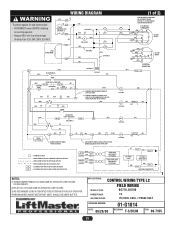
APPLICATIONS: CONTROL WIRING TYPE L2 MODEL TYPES: FIELD WIRING BG770, BG790 HORSEPOWER: VOLTAGE/PHASE: 1/2 115/230V, 60Hz, 1 PHASE ONLY DRAWING NUMBER: DATE: 08/28/00 01-G1014 REVISION: F-3/20/08 ECN: 08-7165 21 WIRING DIAGRAM ...
APPLICATIONS: CONTROL WIRING TYPE L2 MODEL TYPES: FIELD WIRING BG770, BG790 HORSEPOWER: VOLTAGE/PHASE: 1/2 115/230V, 60Hz, 1 PHASE ONLY DRAWING NUMBER: DATE: 08/28/00 01-G1014 REVISION: F-3/20/08 ECN: 08-7165 21 WIRING DIAGRAM ...
BG790 Manual
Page 22
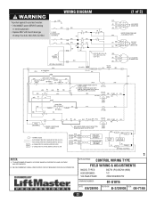
... AS OPERATOR LINE VOLTAGE 24V SECONDARY 2) WE RECOMMEND USING A DEDICATED CIRCUIT BREAKER FOR EACH OPERATOR. 1 APPLICATIONS: CONTROL WIRING TYPE FIELD WIRING & ADJUSTMENTS MODEL TYPES: HORSEPOWER: VOLTAGE/PHASE: BG770 (PG) BG790 (HBG) 1/2 208/230/480/575V DRAWING NUMBER: 01-G1015 DATE: 08/28/00 REVISION: E-3/20/08 ECN: 08-7165 22 WIRING DIAGRAM...
... AS OPERATOR LINE VOLTAGE 24V SECONDARY 2) WE RECOMMEND USING A DEDICATED CIRCUIT BREAKER FOR EACH OPERATOR. 1 APPLICATIONS: CONTROL WIRING TYPE FIELD WIRING & ADJUSTMENTS MODEL TYPES: HORSEPOWER: VOLTAGE/PHASE: BG770 (PG) BG790 (HBG) 1/2 208/230/480/575V DRAWING NUMBER: 01-G1015 DATE: 08/28/00 REVISION: E-3/20/08 ECN: 08-7165 22 WIRING DIAGRAM...
BG790 Manual
Page 23
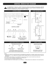
... IS USED. IT WILL NOT STOP OR CLOSE THE GATE. DO NOT USE WITH HOLD OPEN LOOP. 3) 115V UTILITY OUTLET (4 AMP MAX.) PROVIDED ON 115V MODELS ONLY. 4) SEE REVERSE SIDE FOR INTERNAL OPERATOR WIRING. 5) DO NOT CONNECT INPUT POWER LINES TO L1 & L2 TERMINALS. REFER TO INSTRUCTIONS ACCOMPANYING DETECTOR. CONTROL WIRING...
... IS USED. IT WILL NOT STOP OR CLOSE THE GATE. DO NOT USE WITH HOLD OPEN LOOP. 3) 115V UTILITY OUTLET (4 AMP MAX.) PROVIDED ON 115V MODELS ONLY. 4) SEE REVERSE SIDE FOR INTERNAL OPERATOR WIRING. 5) DO NOT CONNECT INPUT POWER LINES TO L1 & L2 TERMINALS. REFER TO INSTRUCTIONS ACCOMPANYING DETECTOR. CONTROL WIRING...
BG790 Manual
Page 24
...USE, OR INABILITY TO USE, THIS PRODUCT. Some states do not allow the exclusion or limitation of purchase. WARRANTY POLICY AND SERVICE LIFTMASTER® ONE YEAR LIMITED WARRANTY The Chamberlain Group, Inc. The proper operation of this product is originally installed, that it is ...SPANS AMERICA FOR INSTALLATION AND SERVICE INFORMATION, CALL OUR TOLL FREE NUMBER 1-800-528-2806 www.liftmaster.com WHEN ORDERING REPAIR PARTS, ALWAYS GIVE THE FOLLOWING INFORMATION: PART NUMBER DESCRIPTION MODEL NUMBER ADDRESS ORDERS TO: THE CHAMBERLAIN GROUP, INC. warrants to the final purchaser of this...
...USE, OR INABILITY TO USE, THIS PRODUCT. Some states do not allow the exclusion or limitation of purchase. WARRANTY POLICY AND SERVICE LIFTMASTER® ONE YEAR LIMITED WARRANTY The Chamberlain Group, Inc. The proper operation of this product is originally installed, that it is ...SPANS AMERICA FOR INSTALLATION AND SERVICE INFORMATION, CALL OUR TOLL FREE NUMBER 1-800-528-2806 www.liftmaster.com WHEN ORDERING REPAIR PARTS, ALWAYS GIVE THE FOLLOWING INFORMATION: PART NUMBER DESCRIPTION MODEL NUMBER ADDRESS ORDERS TO: THE CHAMBERLAIN GROUP, INC. warrants to the final purchaser of this...


