BG790 Manual
Page 2
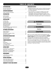
... 5 Operation Preparation 5 INSTALLATION Pad Mounting 6 Arm Fabrication 6 Calculate Arm Length 6 Wiring Specifications 7 Wiring Connections 7 Arm Attachment 8-9 Arm and Turnbuckle Shaft Adjustments 10 Limit Switch Adjustments 11 OPTIONAL ACCESSORIES Vehicle Detectors 12 Radio Controls 12 Card Readers, Keypads or Other 12 Mounting Location 12 OPERATING INSTRUCTIONS Electrical Operation 13 Manual Operation 13 TROUBLESHOOTING Power 14 Accessories 14 Primary Voltage Circuit 15 Low Voltage Circuit 15 General Reference Information 15 REPAIR PARTS Illustrated Parts - The...
... 5 Operation Preparation 5 INSTALLATION Pad Mounting 6 Arm Fabrication 6 Calculate Arm Length 6 Wiring Specifications 7 Wiring Connections 7 Arm Attachment 8-9 Arm and Turnbuckle Shaft Adjustments 10 Limit Switch Adjustments 11 OPTIONAL ACCESSORIES Vehicle Detectors 12 Radio Controls 12 Card Readers, Keypads or Other 12 Mounting Location 12 OPERATING INSTRUCTIONS Electrical Operation 13 Manual Operation 13 TROUBLESHOOTING Power 14 Accessories 14 Primary Voltage Circuit 15 Low Voltage Circuit 15 General Reference Information 15 REPAIR PARTS Illustrated Parts - The...
BG790 Manual
Page 3
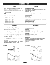
... and side access covers with normally open until CLOSE button is pushed. AUTO/MANUAL switch holds arm in class II circuit. Gear oil is designated by third suffix of access device open button, or loop detector to hold open loop detector is activated or unless CLOSE button wiring has been made, in connectors are included for addition of any access control device with key lock. Activation of gate part number. Not affected by second suffix of motor. Enclosure removable from operator. MOUNTING Pad mount Model BG770...
... and side access covers with normally open until CLOSE button is pushed. AUTO/MANUAL switch holds arm in class II circuit. Gear oil is designated by third suffix of access device open button, or loop detector to hold open loop detector is activated or unless CLOSE button wiring has been made, in connectors are included for addition of any access control device with key lock. Activation of gate part number. Not affected by second suffix of motor. Enclosure removable from operator. MOUNTING Pad mount Model BG770...
BG790 Manual
Page 4
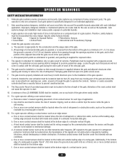
... a vehicular vertical lift gate. Install the gate operator only when: a. The operator is only one on the bottom edge. Swinging gates shall not open position. Additionally, if the bottom edge of a vertical barrier (arm). 4 OPERATOR WARNINGS SAFETY INSTALLATION INFORMATION 1. Improperly designed, installed or maintained systems can create high levels of force in its arc of travel of the gate. Outdoor or easily accessible controls shall have a security feature to reduce...
... a vehicular vertical lift gate. Install the gate operator only when: a. The operator is only one on the bottom edge. Swinging gates shall not open position. Additionally, if the bottom edge of a vertical barrier (arm). 4 OPERATOR WARNINGS SAFETY INSTALLATION INFORMATION 1. Improperly designed, installed or maintained systems can create high levels of force in its arc of travel of the gate. Outdoor or easily accessible controls shall have a security feature to reduce...
BG790 Manual
Page 5
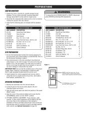
... and length of the electrical cabinet and be in panel shown below. Run electrical power to the site according to gate nameplate located inside service cover) accurately matches the operator that may result. PREPARATIONS CARTON INVENTORY 1. MODEL BG770 PACKING LIST PART NUMBER DESCRIPTION QTY 02-102 Open/Close Push Button 1 07-8007 Gate Arm Hub 1 10-8007M Gate Bracket 1 80-G0187 Key, 1/2 x 1/2 x 1-3/8 1 82-NH38-06 Cone Point Set Screw, 3/8-16 x 3/8 2 82-HN50-25 Hex...
... and length of the electrical cabinet and be in panel shown below. Run electrical power to the site according to gate nameplate located inside service cover) accurately matches the operator that may result. PREPARATIONS CARTON INVENTORY 1. MODEL BG770 PACKING LIST PART NUMBER DESCRIPTION QTY 02-102 Open/Close Push Button 1 07-8007 Gate Arm Hub 1 10-8007M Gate Bracket 1 80-G0187 Key, 1/2 x 1/2 x 1-3/8 1 82-NH38-06 Cone Point Set Screw, 3/8-16 x 3/8 2 82-HN50-25 Hex...
BG790 Manual
Page 6
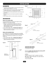
... shaft and concrete pad) = 59" Lower arm should be 59". 6 Refer to set at least two days before installing Arm operator. 5. Allow the concrete to Calculate Arm Length below. 2. Refer to locate electrical Conduit Entry Area 14" conduit inside the hatched 14" x 13" area. 2. If a shorter arm is as needed up to 12' Material: 6: x 1" Pine or Redwood Length up to 8' Figure 4 Arm Extension Figure 5 Arm...
... shaft and concrete pad) = 59" Lower arm should be 59". 6 Refer to set at least two days before installing Arm operator. 5. Allow the concrete to Calculate Arm Length below. 2. Refer to locate electrical Conduit Entry Area 14" conduit inside the hatched 14" x 13" area. 2. If a shorter arm is as needed up to 12' Material: 6: x 1" Pine or Redwood Length up to 8' Figure 4 Arm Extension Figure 5 Arm...
BG790 Manual
Page 7
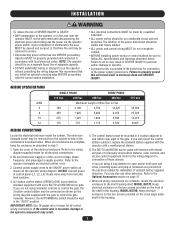
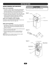
... screws provided on the front of commonly used control stations, radio controls, and access control equipment. However, the AUTO/MANUAL switch should be kept in the housing. 7 Operator MUST be properly grounded and connected in accordance with almost all types of the shelf in separate conduit. • BEFORE installing power wiring or control stations be connected as shown on the wiring diagram supplied with every BG770 and BG790 barrier gate...
... screws provided on the front of commonly used control stations, radio controls, and access control equipment. However, the AUTO/MANUAL switch should be kept in the housing. 7 Operator MUST be properly grounded and connected in accordance with almost all types of the shelf in separate conduit. • BEFORE installing power wiring or control stations be connected as shown on the wiring diagram supplied with every BG770 and BG790 barrier gate...
BG790 Manual
Page 8
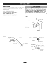
... Bolts Extension Arm S Screw Lift Arm See Detail A Hex Bolt (2) Flat Washers DETAIL A See Detail B Threaded Rod Hex Bolt Flat Washer DETAIL B (2) Flat Washers Hex Nut Hex Nut Hex Nut Flat Washer Threaded Spacer Flat Washer Flat Washer Hex Bolt 8 WARNING When following the procedure below, the motor belt will turn and the drive shaft will move during installation, the top cover...
... Bolts Extension Arm S Screw Lift Arm See Detail A Hex Bolt (2) Flat Washers DETAIL A See Detail B Threaded Rod Hex Bolt Flat Washer DETAIL B (2) Flat Washers Hex Nut Hex Nut Hex Nut Flat Washer Threaded Spacer Flat Washer Flat Washer Hex Bolt 8 WARNING When following the procedure below, the motor belt will turn and the drive shaft will move during installation, the top cover...
BG790 Manual
Page 10
... the pulley on the motor by hand until the crank arm on the gear reducer is not level, loosen the jam nuts at both the top and bottom end of the turnbuckle shaft. 3. CAUTION Turn off power BEFORE making ANY adjustments. Rotate the shaft either clockwise or counterclockwise as necessary until the gate arm is in Closed Position 10 Rotate the...
... the pulley on the motor by hand until the crank arm on the gear reducer is not level, loosen the jam nuts at both the top and bottom end of the turnbuckle shaft. 3. CAUTION Turn off power BEFORE making ANY adjustments. Rotate the shaft either clockwise or counterclockwise as necessary until the gate arm is in Closed Position 10 Rotate the...
BG790 Manual
Page 11
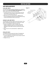
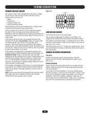
... CLOSE LIMIT SWITCH The AUXILIARY CLOSE limit switch is preset at the factory. When the gate arm is on its lowest position (Figure 12). 2. OPEN LIMIT SWITCH The OPEN limit switch is preset at the factory. If you rotated the pulley in section Arm and Turnbuckle Shaft Adjustments, you will activate just before the CLOSE switch. 2. Loosen the set screw on power and running the unit for the first time. This adjustment may have to reset...
... CLOSE LIMIT SWITCH The AUXILIARY CLOSE limit switch is preset at the factory. When the gate arm is on its lowest position (Figure 12). 2. OPEN LIMIT SWITCH The OPEN limit switch is preset at the factory. If you rotated the pulley in section Arm and Turnbuckle Shaft Adjustments, you will activate just before the CLOSE switch. 2. Loosen the set screw on power and running the unit for the first time. This adjustment may have to reset...
BG790 Manual
Page 12
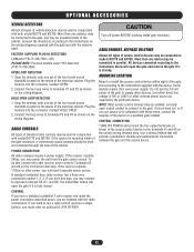
... may connect to operator terminals R3, R1, and R6. Use a wiring method that will need a separate power source. Connect the two loop wires to terminals P1 and P2 as a single button), you may power the unit from the gate control circuit. All devices connected according to the instructions below will open the gate if it is closing. Use either direct line voltage (115V or 230V) or other devices. MOUNTING LOCATION Mount or install the access control device...
... may connect to operator terminals R3, R1, and R6. Use a wiring method that will need a separate power source. Connect the two loop wires to terminals P1 and P2 as a single button), you may power the unit from the gate control circuit. All devices connected according to the instructions below will open the gate if it is closing. Use either direct line voltage (115V or 230V) or other devices. MOUNTING LOCATION Mount or install the access control device...
BG790 Manual
Page 13
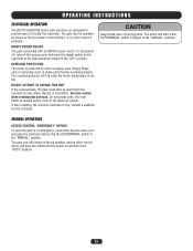
... motor is too hot. The motor will start by either manual or automatic). OPERATING INSTRUCTIONS ELECTRICAL OPERATION The BG770 and BG790 barrier gate operators are designed to provide years of the two button control station, or by other control device will have any effect until the switch is flipped to trip, consult a qualified service company. The overload protector will remain in an emergency, remove the keyed access cover and open the gate...
... motor is too hot. The motor will start by either manual or automatic). OPERATING INSTRUCTIONS ELECTRICAL OPERATION The BG770 and BG790 barrier gate operators are designed to provide years of the two button control station, or by other control device will have any effect until the switch is flipped to trip, consult a qualified service company. The overload protector will remain in an emergency, remove the keyed access cover and open the gate...
BG790 Manual
Page 14
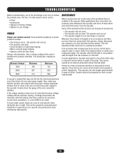
... is removed. Using a volt-ohmmeter, take the same voltage reading with this reading, then there could be caused by an external obstruction device that can only supply approximately 2 amps @ 24Vac. Some of the problems that are credited to check is the wire run , then stops or reverses. The operator will not open or close . • The operator will hold the gate...
... is removed. Using a volt-ohmmeter, take the same voltage reading with this reading, then there could be caused by an external obstruction device that can only supply approximately 2 amps @ 24Vac. Some of the problems that are credited to check is the wire run , then stops or reverses. The operator will not open or close . • The operator will hold the gate...
BG790 Manual
Page 15
... the contactor. If the problem is thought to check is either the full open side of the contactor. The limit switches are attached to the close position. If you have the gate operator model number, voltage, phase, horsepower and a list of all accessories that some of transformer for technical assistance. Please when calling for close direction. Is it is the circuit breaker. Then do...
... the contactor. If the problem is thought to check is either the full open side of the contactor. The limit switches are attached to the close position. If you have the gate operator model number, voltage, phase, horsepower and a list of all accessories that some of transformer for technical assistance. Please when calling for close direction. Is it is the circuit breaker. Then do...
BG790 Manual
Page 17
Panel Mounting Bracket Shaft 4 Bolt Flange Female Rod End Female Rod End V-Belt 8" Pulley 2" Pulley Transformer SPDT Limit Switch Rocker Switch Toggle Outlet 24Vac DPDT Relay Switch Box Duplex Outlet Cover 1-32 x 1/8 Spacer Nylon Sensor Spacer Barrier Gate Gear Reducer 8 Position Terminal Block 10 Position Terminal Block Single Arm (Optional) 6-32 Tinnerman Nut 3/4 Flat Washer Access Panel Lock 1/2-20 x 1-1/4 Hex Head Bolt 3/4-10 x 3 Hex Head Bolt 3/4-16 Jam Nut 3/4-16 Left Hand...
Panel Mounting Bracket Shaft 4 Bolt Flange Female Rod End Female Rod End V-Belt 8" Pulley 2" Pulley Transformer SPDT Limit Switch Rocker Switch Toggle Outlet 24Vac DPDT Relay Switch Box Duplex Outlet Cover 1-32 x 1/8 Spacer Nylon Sensor Spacer Barrier Gate Gear Reducer 8 Position Terminal Block 10 Position Terminal Block Single Arm (Optional) 6-32 Tinnerman Nut 3/4 Flat Washer Access Panel Lock 1/2-20 x 1-1/4 Hex Head Bolt 3/4-10 x 3 Hex Head Bolt 3/4-16 Jam Nut 3/4-16 Left Hand...
BG790 Manual
Page 19
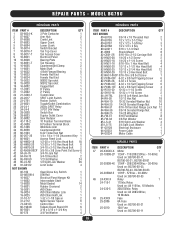
... x 2-1/2 Hex Head Bolt 2 3/8-16 x 3/8 Cone Point Set Screw 8 3/4-16 Jam Nut 1 3/4-10 Hex Nut 2 1/2 Flat Washer 24 1/2 Split Lock Washer 38 Limit Collar 4 Open/Close Key Switch 1 DIN Rail 1 Electrical Panel Hanger Kit 1 Intermediate Shaft 1 Metal Gasket 14 Rubber Grommet 2 #50 Chain 1 #50 Chain Master Link 1 #50 Chain Half Link 1 1-32 x 1-1/8 Spacer 2 Nylon Sensor Spacer 6 Control Box 1 Failsafe Board Stand Off 8 3/16 x 3/16 x 1-3/4 Key 1 3/4 Flat Washer 4 ITEM PART # DESCRIPTION QTY NOT SHOWN 80-G0135 3/8-16...
... x 2-1/2 Hex Head Bolt 2 3/8-16 x 3/8 Cone Point Set Screw 8 3/4-16 Jam Nut 1 3/4-10 Hex Nut 2 1/2 Flat Washer 24 1/2 Split Lock Washer 38 Limit Collar 4 Open/Close Key Switch 1 DIN Rail 1 Electrical Panel Hanger Kit 1 Intermediate Shaft 1 Metal Gasket 14 Rubber Grommet 2 #50 Chain 1 #50 Chain Master Link 1 #50 Chain Half Link 1 1-32 x 1-1/8 Spacer 2 Nylon Sensor Spacer 6 Control Box 1 Failsafe Board Stand Off 8 3/16 x 3/16 x 1-3/4 Key 1 3/4 Flat Washer 4 ITEM PART # DESCRIPTION QTY NOT SHOWN 80-G0135 3/8-16...
BG790 Manual
Page 20
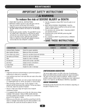
.... 8. MAINTENANCE IMPORTANT SAFETY INSTRUCTIONS WARNING To reduce the risk of INJURY or DEATH. 5. KEEP GATES PROPERLY MAINTAINED. Motor and shaft bearing normally should never need replacement. Failure to gate hardware. 7. Use the emergency release ONLY when the gate is sealed in the gear reducer is not moving. 6. Read the owner's manual. Pedestrians MUST use Mobilube C SAE140 or equivalent. DESCRIPTION External Safety Systems Gate Caution Systems Drive Chain (see notes) Sprockets and...
.... 8. MAINTENANCE IMPORTANT SAFETY INSTRUCTIONS WARNING To reduce the risk of INJURY or DEATH. 5. KEEP GATES PROPERLY MAINTAINED. Motor and shaft bearing normally should never need replacement. Failure to gate hardware. 7. Use the emergency release ONLY when the gate is sealed in the gear reducer is not moving. 6. Read the owner's manual. Pedestrians MUST use Mobilube C SAE140 or equivalent. DESCRIPTION External Safety Systems Gate Caution Systems Drive Chain (see notes) Sprockets and...
BG790 Manual
Page 21
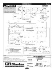
... SEC. (W) (PUR) 1) REMOVE JUMPER WHEN TIMER TO CLOSE IS USED. 2) REMOVE JUMPER TO CAUSE GATE ARM TO CLOSE IMMEDIATELY UNLESS HOLD OPEN LOOP IS ACTIVATED. (OR) OP 56 1 CL 2 (1 of rating. FOR BG770, INTERCHANGE GREEN AND RED WIRES (GN) BR (BK) (W) BR (R) 115V MOTOR CONNECTION YW 4 2 8 BK 5 OR BL 1 3 O/L SEE NOTE 4 (GN) W BR 4 (BK) R 8 (W) BK Y BL BR 523 (R) OR 1 O/L SEE NOTE 4 230V MOTOR CONNECTION (BL) FUSE 3.2A R1...
... SEC. (W) (PUR) 1) REMOVE JUMPER WHEN TIMER TO CLOSE IS USED. 2) REMOVE JUMPER TO CAUSE GATE ARM TO CLOSE IMMEDIATELY UNLESS HOLD OPEN LOOP IS ACTIVATED. (OR) OP 56 1 CL 2 (1 of rating. FOR BG770, INTERCHANGE GREEN AND RED WIRES (GN) BR (BK) (W) BR (R) 115V MOTOR CONNECTION YW 4 2 8 BK 5 OR BL 1 3 O/L SEE NOTE 4 (GN) W BR 4 (BK) R 8 (W) BK Y BL BR 523 (R) OR 1 O/L SEE NOTE 4 230V MOTOR CONNECTION (BL) FUSE 3.2A R1...
BG790 Manual
Page 22
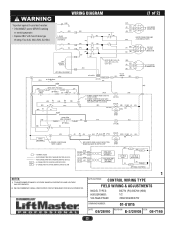
.../MANUAL O/L IN SEE NOTE 1 (BL) MOTOR (OR) FUSE 3.2A J1 J2 24V SEC. (W) OPEN (OR) (GN) OPEN LOOP-PRESENCE (W) J3-4 J3-6 SENSING EDGE (OPTIONAL) AUX. (W) CLOSE L/S GY 3 7 1 (PUR) (BR) R1 1) REMOVE JUMPER WHEN TIMER TO CLOSE IS USED. 24V COIL (OR) R1 (GN) R2 (GN) (OR) 14 OP 13 (OR) (OR) R1 (Y) CLOSE 5 TD-2 2) REMOVE JUMPER TO CAUSE GATE ARM TO CLOSE IMMEDIATELY UNLESS HOLD OPEN LOOP IS...
.../MANUAL O/L IN SEE NOTE 1 (BL) MOTOR (OR) FUSE 3.2A J1 J2 24V SEC. (W) OPEN (OR) (GN) OPEN LOOP-PRESENCE (W) J3-4 J3-6 SENSING EDGE (OPTIONAL) AUX. (W) CLOSE L/S GY 3 7 1 (PUR) (BR) R1 1) REMOVE JUMPER WHEN TIMER TO CLOSE IS USED. 24V COIL (OR) R1 (GN) R2 (GN) (OR) 14 OP 13 (OR) (OR) R1 (Y) CLOSE 5 TD-2 2) REMOVE JUMPER TO CAUSE GATE ARM TO CLOSE IMMEDIATELY UNLESS HOLD OPEN LOOP IS...
BG790 Manual
Page 23
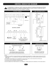
... POWER FOR LOOP DETECTORS SHOULD BE DIRECTLY WIRED TO DETECTOR ITSELF. POWER LINES MUST BE CONNECTED TO THE POWER SWITCH. 23 CONTROL CONNECTION DIAGRAM IT IS IMPORTANT TO READ ALL SAFETY RULES INCLUDED IN THE INSTALLATION MANUAL BEFORE BEGINNING INSTALLATION. IF THIS JUMPER IS NOT REMOVED, ARM WILL REMAIN OPEN UNTIL A VEHICLE ENTERS AND EXITS THE HOLD OPEN LOOP. 2) ADD JUMPER FROM TERMINAL #8 TO #9 WHENEVER CLOSE BUTTON IS USED. NOTES: 1) REMOVE THIS JUMPER TO CAUSE GATE ARM...
... POWER FOR LOOP DETECTORS SHOULD BE DIRECTLY WIRED TO DETECTOR ITSELF. POWER LINES MUST BE CONNECTED TO THE POWER SWITCH. 23 CONTROL CONNECTION DIAGRAM IT IS IMPORTANT TO READ ALL SAFETY RULES INCLUDED IN THE INSTALLATION MANUAL BEFORE BEGINNING INSTALLATION. IF THIS JUMPER IS NOT REMOVED, ARM WILL REMAIN OPEN UNTIL A VEHICLE ENTERS AND EXITS THE HOLD OPEN LOOP. 2) ADD JUMPER FROM TERMINAL #8 TO #9 WHENEVER CLOSE BUTTON IS USED. NOTES: 1) REMOVE THIS JUMPER TO CAUSE GATE ARM...
BG790 Manual
Page 24
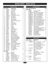
... SPANS AMERICA FOR INSTALLATION AND SERVICE INFORMATION, CALL OUR TOLL FREE NUMBER 1-800-528-2806 www.liftmaster.com WHEN ORDERING REPAIR PARTS, ALWAYS GIVE THE FOLLOWING INFORMATION: PART NUMBER DESCRIPTION MODEL NUMBER ADDRESS ORDERS TO: THE CHAMBERLAIN GROUP, INC. Then send this limited warranty, will be repaired or replaced with those instructions will be defective and covered by this limited warranty, call . Please include a brief description of the problem and a dated...
... SPANS AMERICA FOR INSTALLATION AND SERVICE INFORMATION, CALL OUR TOLL FREE NUMBER 1-800-528-2806 www.liftmaster.com WHEN ORDERING REPAIR PARTS, ALWAYS GIVE THE FOLLOWING INFORMATION: PART NUMBER DESCRIPTION MODEL NUMBER ADDRESS ORDERS TO: THE CHAMBERLAIN GROUP, INC. Then send this limited warranty, will be repaired or replaced with those instructions will be defective and covered by this limited warranty, call . Please include a brief description of the problem and a dated...


