BG790 Manual
Page 1
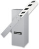
OWNER'S MANUAL MODELS BG770 & BG790 VEHICULAR BARRIER GATE OPERATOR MODELS BG770 AND BG790 ARE FOR VEHICULAR PASSAGE GATES ONLY AND ARE NOT INTENDED FOR PEDESTRIAN PASSAGE GATE USE
OWNER'S MANUAL MODELS BG770 & BG790 VEHICULAR BARRIER GATE OPERATOR MODELS BG770 AND BG790 ARE FOR VEHICULAR PASSAGE GATES ONLY AND ARE NOT INTENDED FOR PEDESTRIAN PASSAGE GATE USE
BG790 Manual
Page 2
...alert you to the possibility of damage to your gate and/or the gate operator if you MUST read and fully understand this manual and follow ALL safety instructions. • These instructions are not intended to the possibility of the purchaser, designer, installer and end... user to highlight certain safety related issues. Read them . Model BG790 19 MAINTENANCE Limited Bearing Lubrication 20 Grease Turnbuckle 20 WIRING DIAGRAMS Single Phase Wiring Diagram 21 Three Phase Wiring Diagram 22 Control Connection...
...alert you to the possibility of damage to your gate and/or the gate operator if you MUST read and fully understand this manual and follow ALL safety instructions. • These instructions are not intended to the possibility of the purchaser, designer, installer and end... user to highlight certain safety related issues. Read them . Model BG790 19 MAINTENANCE Limited Bearing Lubrication 20 Grease Turnbuckle 20 WIRING DIAGRAMS Single Phase Wiring Diagram 21 Three Phase Wiring Diagram 22 Control Connection...
BG790 Manual
Page 3
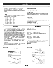
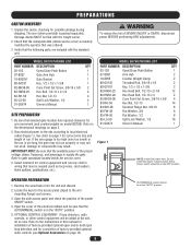
... Adjustable, driven limit switches, operate in vertical position. Not affected by third suffix of motor. POWER ON/OFF SWITCH Enclosed toggle switch, HP rated. AUTO/MANUAL switch holds arm in class II circuit. For amp draw, see motor nameplate. -11; 115Vac, 1 Phase, 60Hz -21; 230Vac, 1 Phase, 60Hz ... operators) thermal overload. MECHANICAL SPEED REDUCTION Wormgear-in-oil-bath, 60:1 ARM TYPE MODEL BG770: One piece type to 15' MODEL BG790: Counterweighted wishbone type to 24' DIMENSIONS 22" 44" 35" Typical Installation Typical Installation 3 Gear oil is designated by removal of gate...
... Adjustable, driven limit switches, operate in vertical position. Not affected by third suffix of motor. POWER ON/OFF SWITCH Enclosed toggle switch, HP rated. AUTO/MANUAL switch holds arm in class II circuit. For amp draw, see motor nameplate. -11; 115Vac, 1 Phase, 60Hz -21; 230Vac, 1 Phase, 60Hz ... operators) thermal overload. MECHANICAL SPEED REDUCTION Wormgear-in-oil-bath, 60:1 ARM TYPE MODEL BG770: One piece type to 15' MODEL BG790: Counterweighted wishbone type to 24' DIMENSIONS 22" 44" 35" Typical Installation Typical Installation 3 Gear oil is designated by removal of gate...
BG790 Manual
Page 4
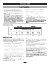
... travel of two (2) WARNING SIGNS shall be installed, one that the gate covers in both inside and outside of a vehicular vertical lift gate. Reference owner's manual regarding placement of non-contact sensor for vehicles. A hard wired contact sensor shall be located and its function as when a vehicle trips the sensor while...
... travel of two (2) WARNING SIGNS shall be installed, one that the gate covers in both inside and outside of a vehicular vertical lift gate. Reference owner's manual regarding placement of non-contact sensor for vehicles. A hard wired contact sensor shall be located and its function as when a vehicle trips the sensor while...
BG790 Manual
Page 5
...82-HN50-25 Hex Bolt, 1/2-13 x 2-1/4 4 82-RH-50 Hex Nut, 1/2-13 4 85-LS-50 Split Lock Washer, 1/2 4 01-G0674 Owner's Manual 1 SITE PREPARATION 1. Select locations for correct wire size and length of the electrical cabinet and be added at all. OPERATOR PREPARATION 1. Refer to the instructions...small) or the run is the proper voltage, phase, frequency, and amperage to the dimensional drawings on model BG790). Refer to local electrical codes (Figure 1). MODEL BG790 PACKING LIST PART NUMBER DESCRIPTION QTY 02-102 Open/Close Push Button 1 07-8007 Arm Hub 2 10-8055 ...
...82-HN50-25 Hex Bolt, 1/2-13 x 2-1/4 4 82-RH-50 Hex Nut, 1/2-13 4 85-LS-50 Split Lock Washer, 1/2 4 01-G0674 Owner's Manual 1 SITE PREPARATION 1. Select locations for correct wire size and length of the electrical cabinet and be added at all. OPERATOR PREPARATION 1. Refer to the instructions...small) or the run is the proper voltage, phase, frequency, and amperage to the dimensional drawings on model BG790). Refer to local electrical codes (Figure 1). MODEL BG790 PACKING LIST PART NUMBER DESCRIPTION QTY 02-102 Open/Close Push Button 1 07-8007 Arm Hub 2 10-8055 ...
BG790 Manual
Page 7
...also use other detectors. Connect power supply wires to the ON/OFF power switch as described in step 7. 1. The BG770 and BG790 barrier gates will mount the control station outdoors, replace the standard station supplied with the operator with almost all control wiring connections.... control stations be kept in the "AUTO" position. You may be connected as standard equipment with the gate to control the gate manually. When all electrical connections. 2. MODEL BG770: Hang electrical enclosure on the two screws provided on electrical cabinet cover. 3. INSTALLATION WARNING...
...also use other detectors. Connect power supply wires to the ON/OFF power switch as described in step 7. 1. The BG770 and BG790 barrier gates will mount the control station outdoors, replace the standard station supplied with the operator with almost all control wiring connections.... control stations be kept in the "AUTO" position. You may be connected as standard equipment with the gate to control the gate manually. When all electrical connections. 2. MODEL BG770: Hang electrical enclosure on the two screws provided on electrical cabinet cover. 3. INSTALLATION WARNING...
BG790 Manual
Page 13
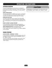
...move the toggle switch on the cover of trouble-free operation. On one phase units, the reset button is protected by either manual or automatic). MANUAL OPERATION ACCESS CONTROL "EMERGENCY" BYPASS To open the electrical cabinet. OVERLOAD PROTECTION The motor is located on the right side of ...trip when the motor temperature is provided with an ON/OFF power switch. If after resetting, the overload continues to the "MANUAL" position. OPERATING INSTRUCTIONS ELECTRICAL OPERATION The BG770 and BG790 barrier gate operators are designed to provide years of the electrical cabinet.
...move the toggle switch on the cover of trouble-free operation. On one phase units, the reset button is protected by either manual or automatic). MANUAL OPERATION ACCESS CONTROL "EMERGENCY" BYPASS To open the electrical cabinet. OVERLOAD PROTECTION The motor is located on the right side of ...trip when the motor temperature is provided with an ON/OFF power switch. If after resetting, the overload continues to the "MANUAL" position. OPERATING INSTRUCTIONS ELECTRICAL OPERATION The BG770 and BG790 barrier gate operators are designed to provide years of the electrical cabinet.
BG790 Manual
Page 15
...contact your local distributor or dealer. There are five (4) items in the low voltage control circuit. If the first two check out okay, then manually disconnect the operator from one for open side of the contactor's contact points. If the contactor is recommended that are : • Motor •... carefully check all of the contactor. If there is the incoming power. Did the operator run in the controller (Model BG770 uses a manual reset overload). now press down on the contactor; Figure 13 Contactor LOW VOLTAGE CIRCUIT The first thing to check is voltage at the switch...
...contact your local distributor or dealer. There are five (4) items in the low voltage control circuit. If the first two check out okay, then manually disconnect the operator from one for open side of the contactor's contact points. If the contactor is recommended that are : • Motor •... carefully check all of the contactor. If there is the incoming power. Did the operator run in the controller (Model BG770 uses a manual reset overload). now press down on the contactor; Figure 13 Contactor LOW VOLTAGE CIRCUIT The first thing to check is voltage at the switch...
BG790 Manual
Page 20
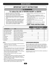
...reset after any debris in the area. Pick up any major drive chain adjustments. • BG790: If lubricating chain, use . 20 Using a VOM, double check the incoming voltage to ...MUST reverse on the gate's frequency of the operator. Failure to be performed by a LiftMaster professional. 10.SAVE THESE INSTRUCTIONS. KEEP GATES PROPERLY MAINTAINED. Disconnect ALL power BEFORE performing ANY... force or the limit of the operator and the area around the operator. Read the owner's manual. Never use grease or silicone spray. • When servicing, please do some voltage readings of...
...reset after any debris in the area. Pick up any major drive chain adjustments. • BG790: If lubricating chain, use . 20 Using a VOM, double check the incoming voltage to ...MUST reverse on the gate's frequency of the operator. Failure to be performed by a LiftMaster professional. 10.SAVE THESE INSTRUCTIONS. KEEP GATES PROPERLY MAINTAINED. Disconnect ALL power BEFORE performing ANY... force or the limit of the operator and the area around the operator. Read the owner's manual. Never use grease or silicone spray. • When servicing, please do some voltage readings of...
BG790 Manual
Page 21
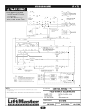
... 115V ONLY (BK) 0/L (BK) (BK) IR SEE NOTE 2 (BK) 115V ONLY (BK) (W) CL 43 4 OP 3 2 OP 1 6 CL 5 (OR) 230V ONLY (YEL) (YEL) AUTO/MANUAL OPEN OPEN LOOP-PRESENCE (GN) (W) J3-4 J3-6 SENSING EDGE (OPTIONAL) AUX. (W) CLOSE L/S (GY) 3 7 1 (OR) R1 (GN) R2 (GN) 5 (OR) 14 OP 13 (OR) R1...ONLY with fuse of same type of 2) MOTOR CONNECTION SAME AS INCOMING POWER. APPLICATIONS: CONTROL WIRING TYPE L2 MODEL TYPES: FIELD WIRING BG770, BG790 HORSEPOWER: VOLTAGE/PHASE: 1/2 115/230V, 60Hz, 1 PHASE ONLY DRAWING NUMBER: DATE: 08/28/00 01-G1014 REVISION: F-3/20/08 ECN: 08-...
... 115V ONLY (BK) 0/L (BK) (BK) IR SEE NOTE 2 (BK) 115V ONLY (BK) (W) CL 43 4 OP 3 2 OP 1 6 CL 5 (OR) 230V ONLY (YEL) (YEL) AUTO/MANUAL OPEN OPEN LOOP-PRESENCE (GN) (W) J3-4 J3-6 SENSING EDGE (OPTIONAL) AUX. (W) CLOSE L/S (GY) 3 7 1 (OR) R1 (GN) R2 (GN) 5 (OR) 14 OP 13 (OR) R1...ONLY with fuse of same type of 2) MOTOR CONNECTION SAME AS INCOMING POWER. APPLICATIONS: CONTROL WIRING TYPE L2 MODEL TYPES: FIELD WIRING BG770, BG790 HORSEPOWER: VOLTAGE/PHASE: 1/2 115/230V, 60Hz, 1 PHASE ONLY DRAWING NUMBER: DATE: 08/28/00 01-G1014 REVISION: F-3/20/08 ECN: 08-...
BG790 Manual
Page 22
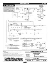
... 208V-(R), 230V-(OR), 480-(VT), 575V-(GY) (GN) (BL) 1 (R) 2 (W) (BL) 3 J 575V MOTOR CONNECTION J (OPTIONAL EQUIPMENT) (YEL) 4 (YEL) AUTO/MANUAL O/L IN SEE NOTE 1 (BL) MOTOR (OR) FUSE 3.2A J1 J2 24V SEC. (W) OPEN (OR) (GN) OPEN LOOP-PRESENCE (W) J3-4 J3-6 SENSING EDGE (OPTIONAL)... DEDICATED CIRCUIT BREAKER FOR EACH OPERATOR. 1 APPLICATIONS: CONTROL WIRING TYPE FIELD WIRING & ADJUSTMENTS MODEL TYPES: HORSEPOWER: VOLTAGE/PHASE: BG770 (PG) BG790 (HBG) 1/2 208/230/480/575V DRAWING NUMBER: 01-G1015 DATE: 08/28/00 REVISION: E-3/20/08 ECN: 08-7165 22 WIRING ...
... 208V-(R), 230V-(OR), 480-(VT), 575V-(GY) (GN) (BL) 1 (R) 2 (W) (BL) 3 J 575V MOTOR CONNECTION J (OPTIONAL EQUIPMENT) (YEL) 4 (YEL) AUTO/MANUAL O/L IN SEE NOTE 1 (BL) MOTOR (OR) FUSE 3.2A J1 J2 24V SEC. (W) OPEN (OR) (GN) OPEN LOOP-PRESENCE (W) J3-4 J3-6 SENSING EDGE (OPTIONAL)... DEDICATED CIRCUIT BREAKER FOR EACH OPERATOR. 1 APPLICATIONS: CONTROL WIRING TYPE FIELD WIRING & ADJUSTMENTS MODEL TYPES: HORSEPOWER: VOLTAGE/PHASE: BG770 (PG) BG790 (HBG) 1/2 208/230/480/575V DRAWING NUMBER: 01-G1015 DATE: 08/28/00 REVISION: E-3/20/08 ECN: 08-7165 22 WIRING ...
BG790 Manual
Page 23
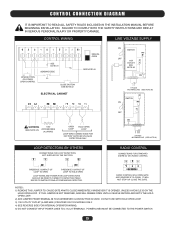
... TERMINALS. CONTROL WIRING LINE VOLTAGE SUPPLY OPEN BUTTON OR OTHER OPEN CONTROL SEE NOTE #1 SENSING EDGE CLOSE BUTTON SEE NOTE #2 ELECTRICAL CABINET MANUAL OPEN SEE NOTE #2 WARNING 115V (SEE NOTE #5) ACCESSORIES (0.2A MAX) OPEN LOOP HOLD OPEN LOOP LOOP WIRE CONNECTIONS FOR FACTORY SUPPLIED...SHOULD BE DIRECTLY WIRED TO DETECTOR ITSELF. CONTROL CONNECTION DIAGRAM IT IS IMPORTANT TO READ ALL SAFETY RULES INCLUDED IN THE INSTALLATION MANUAL BEFORE BEGINNING INSTALLATION. REFER TO INSTRUCTIONS ACCOMPANYING DETECTOR. IF THIS JUMPER IS NOT REMOVED, ARM WILL REMAIN OPEN UNTIL A ...
... TERMINALS. CONTROL WIRING LINE VOLTAGE SUPPLY OPEN BUTTON OR OTHER OPEN CONTROL SEE NOTE #1 SENSING EDGE CLOSE BUTTON SEE NOTE #2 ELECTRICAL CABINET MANUAL OPEN SEE NOTE #2 WARNING 115V (SEE NOTE #5) ACCESSORIES (0.2A MAX) OPEN LOOP HOLD OPEN LOOP LOOP WIRE CONNECTIONS FOR FACTORY SUPPLIED...SHOULD BE DIRECTLY WIRED TO DETECTOR ITSELF. CONTROL CONNECTION DIAGRAM IT IS IMPORTANT TO READ ALL SAFETY RULES INCLUDED IN THE INSTALLATION MANUAL BEFORE BEGINNING INSTALLATION. REFER TO INSTRUCTIONS ACCOMPANYING DETECTOR. IF THIS JUMPER IS NOT REMOVED, ARM WILL REMAIN OPEN UNTIL A ...


