BG790 Manual
Page 2
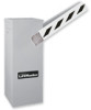
Model BG790 19 MAINTENANCE Limited Bearing Lubrication 20 Grease Turnbuckle 20 WIRING DIAGRAMS Single Phase Wiring Diagram 21 Three Phase Wiring Diagram 22 Control Connection Diagram 23 WARRANTY POLICY AND SERVICE 24 IMPORTANT NOTES • BEFORE attempting to install, operate or maintain... gate operator if you to the possibility of SERIOUS INJURY or DEATH if you to highlight certain safety related issues. Model BG770 17 Illustrated Parts - The hazard may come from something mechanical or from electric shock. TABLE OF CONTENTS SPECIFICATIONS Operator Specifications ...
Model BG790 19 MAINTENANCE Limited Bearing Lubrication 20 Grease Turnbuckle 20 WIRING DIAGRAMS Single Phase Wiring Diagram 21 Three Phase Wiring Diagram 22 Control Connection Diagram 23 WARRANTY POLICY AND SERVICE 24 IMPORTANT NOTES • BEFORE attempting to install, operate or maintain... gate operator if you to the possibility of SERIOUS INJURY or DEATH if you to highlight certain safety related issues. Model BG770 17 Illustrated Parts - The hazard may come from something mechanical or from electric shock. TABLE OF CONTENTS SPECIFICATIONS Operator Specifications ...
BG790 Manual
Page 7
... connections are complete, hang the enclosure as standard equipment with almost all control wiring connections. Refer to the operator nameplate on the operator wiring diagram. If the control wire is of the correct voltage, phase, frequency, and amperage to supply operator. The BG770 and BG790 barrier gates will mount the control station outdoors, replace the...
... connections are complete, hang the enclosure as standard equipment with almost all control wiring connections. Refer to the operator nameplate on the operator wiring diagram. If the control wire is of the correct voltage, phase, frequency, and amperage to supply operator. The BG770 and BG790 barrier gates will mount the control station outdoors, replace the...
BG790 Manual
Page 12
...the instructions on the control terminal strip. Some devices require their own power supply. Use a wiring method that will open output contact to connect to the instructions supplied with both model BG770 and BG790. Plug the harness into the connector marked "HOLD OPEN." 2. If the receiver...SUPPLIED PLUG-IN DETECTORS LiftMaster P/N 71-416-7NH = 24V PLEASE NOTE: Previous models used and extended through the side of the gate and according to the gate. OPEN LOOP DETECTOR 1. Connect the two loop wires to terminals P3 and P4 as shown on the wiring diagram. HOLD OPEN LOOP ...
...the instructions on the control terminal strip. Some devices require their own power supply. Use a wiring method that will open output contact to connect to the instructions supplied with both model BG770 and BG790. Plug the harness into the connector marked "HOLD OPEN." 2. If the receiver...SUPPLIED PLUG-IN DETECTORS LiftMaster P/N 71-416-7NH = 24V PLEASE NOTE: Previous models used and extended through the side of the gate and according to the gate. OPEN LOOP DETECTOR 1. Connect the two loop wires to terminals P3 and P4 as shown on the wiring diagram. HOLD OPEN LOOP ...
BG790 Manual
Page 15
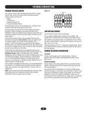
... terminals 3 and 6. Does the gate move freely? If there is power, then check for assistance, make sure you have their own wiring diagram. It if did , the problem may have the gate operator model number, voltage, phase, horsepower and a list of the contactor. ...the controller (Model BG770 uses a manual reset overload). To activate the motor in this on the contactor; now press down on 2. you probably have a separate overload in the low voltage control circuit. Are there unprotected pinch points? WIRING DIAGRAM Always reference the wiring diagram that it be ...
... terminals 3 and 6. Does the gate move freely? If there is power, then check for assistance, make sure you have their own wiring diagram. It if did , the problem may have the gate operator model number, voltage, phase, horsepower and a list of the contactor. ...the controller (Model BG770 uses a manual reset overload). To activate the motor in this on the contactor; now press down on 2. you probably have a separate overload in the low voltage control circuit. Are there unprotected pinch points? WIRING DIAGRAM Always reference the wiring diagram that it be ...
BG790 Manual
Page 21
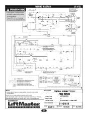
...AS OPERATOR LINE VOLTAGE. 3) WE RECOMMEND USING A DEDICATED CIRCUIT BREAKER FOR EACH OPERATOR. 4) BROWN WIRES INSIDE MOTOR NOT USED, SHOULD BE WIRE NUTTED. WIRING DIAGRAM To protect against fire and electrocution: • DISCONNECT power BEFORE installing or servicing operator. •... Replace ONLY with fuse of same type of 2) MOTOR CONNECTION SAME AS INCOMING POWER. APPLICATIONS: CONTROL WIRING TYPE L2 MODEL TYPES: FIELD WIRING BG770, BG790...
...AS OPERATOR LINE VOLTAGE. 3) WE RECOMMEND USING A DEDICATED CIRCUIT BREAKER FOR EACH OPERATOR. 4) BROWN WIRES INSIDE MOTOR NOT USED, SHOULD BE WIRE NUTTED. WIRING DIAGRAM To protect against fire and electrocution: • DISCONNECT power BEFORE installing or servicing operator. •... Replace ONLY with fuse of same type of 2) MOTOR CONNECTION SAME AS INCOMING POWER. APPLICATIONS: CONTROL WIRING TYPE L2 MODEL TYPES: FIELD WIRING BG770, BG790...
BG790 Manual
Page 22
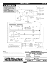
...CONNECTION MOTOR CONNECTION SAME (GN) AS INCOMING POWER (BL) (R) (W) (BL) 1 74 J 28 5 208/230V MOTOR 3 9 6 J CONNECTION 115V GEARBOX HEATER (BK) H2 WIRE COLOR: 208V-(R), 230V-(OR), 480-(VT), 575V-(GY) (GN) (BL) 1 (R) 2 (W) (BL) 3 J 575V MOTOR CONNECTION J (OPTIONAL EQUIPMENT) (YEL) 4 (YEL)... OPERATOR. 1 APPLICATIONS: CONTROL WIRING TYPE FIELD WIRING & ADJUSTMENTS MODEL TYPES: HORSEPOWER: VOLTAGE/PHASE: BG770 (PG) BG790 (HBG) 1/2 208/230/480/575V DRAWING NUMBER: 01-G1015 DATE: 08/28/00 REVISION: E-3/20/08 ECN: 08-7165 22 WIRING DIAGRAM (1 of 2) To protect against...
...CONNECTION MOTOR CONNECTION SAME (GN) AS INCOMING POWER (BL) (R) (W) (BL) 1 74 J 28 5 208/230V MOTOR 3 9 6 J CONNECTION 115V GEARBOX HEATER (BK) H2 WIRE COLOR: 208V-(R), 230V-(OR), 480-(VT), 575V-(GY) (GN) (BL) 1 (R) 2 (W) (BL) 3 J 575V MOTOR CONNECTION J (OPTIONAL EQUIPMENT) (YEL) 4 (YEL)... OPERATOR. 1 APPLICATIONS: CONTROL WIRING TYPE FIELD WIRING & ADJUSTMENTS MODEL TYPES: HORSEPOWER: VOLTAGE/PHASE: BG770 (PG) BG790 (HBG) 1/2 208/230/480/575V DRAWING NUMBER: 01-G1015 DATE: 08/28/00 REVISION: E-3/20/08 ECN: 08-7165 22 WIRING DIAGRAM (1 of 2) To protect against...
BG790 Manual
Page 23
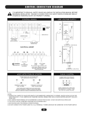
... AND REVERSE IF CLOSING. CONTROL WIRING LINE VOLTAGE SUPPLY OPEN BUTTON OR...WARNING 115V (SEE NOTE #5) ACCESSORIES (0.2A MAX) OPEN LOOP HOLD OPEN LOOP LOOP WIRE CONNECTIONS FOR FACTORY SUPPLIED (PLUG-IN) DETECTORS ONLY ON OFF SWITCH (BK) 115V (W)...FOR STANDARD 3-WIRE 24 VAC RADIO CONTROL PRESENCE CONTACT OF LOOP TO OPEN PRESENCE CONTACT OF... LOOP TO HOLD OPEN LOOP WIRES AND POWER FOR LOOP DETECTORS SHOULD BE DIRECTLY WIRED TO DETECTOR ITSELF. NOTES: 1) ...PROVIDED ON 115V MODELS ONLY. 4) SEE REVERSE SIDE FOR INTERNAL OPERATOR WIRING. 5) DO NOT CONNECT INPUT POWER LINES TO L1 & L2 TERMINALS....
... AND REVERSE IF CLOSING. CONTROL WIRING LINE VOLTAGE SUPPLY OPEN BUTTON OR...WARNING 115V (SEE NOTE #5) ACCESSORIES (0.2A MAX) OPEN LOOP HOLD OPEN LOOP LOOP WIRE CONNECTIONS FOR FACTORY SUPPLIED (PLUG-IN) DETECTORS ONLY ON OFF SWITCH (BK) 115V (W)...FOR STANDARD 3-WIRE 24 VAC RADIO CONTROL PRESENCE CONTACT OF LOOP TO OPEN PRESENCE CONTACT OF... LOOP TO HOLD OPEN LOOP WIRES AND POWER FOR LOOP DETECTORS SHOULD BE DIRECTLY WIRED TO DETECTOR ITSELF. NOTES: 1) ...PROVIDED ON 115V MODELS ONLY. 4) SEE REVERSE SIDE FOR INTERNAL OPERATOR WIRING. 5) DO NOT CONNECT INPUT POWER LINES TO L1 & L2 TERMINALS....


