
3275 Manual
Page 2
...spreader 6 Tighten the chain 7 Installation 7-22 Installation safety instructions 7 Determine the header bracket location 8 Install the header bracket 9 Attach the rail to the header bracket 10 Position the opener 10 Hang the opener 11 Install the door control 12 Install the light 13 Attach the emergency...To erase all codes 31 3-Button remotes 31 To add, reprogram or change a Keyless Entry PIN 32 Repair Parts 33-34 Rail assembly parts 33 Installation parts 33 Motor unit assembly parts 34 Accessories 35 Repair Parts and Service 36 Warranty 36 INTRODUCTION Safety ...
...spreader 6 Tighten the chain 7 Installation 7-22 Installation safety instructions 7 Determine the header bracket location 8 Install the header bracket 9 Attach the rail to the header bracket 10 Position the opener 10 Hang the opener 11 Install the door control 12 Install the light 13 Attach the emergency...To erase all codes 31 3-Button remotes 31 To add, reprogram or change a Keyless Entry PIN 32 Repair Parts 33-34 Rail assembly parts 33 Installation parts 33 Motor unit assembly parts 34 Accessories 35 Repair Parts and Service 36 Warranty 36 INTRODUCTION Safety ...
3275 Manual
Page 5
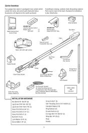
... also listed below . Multi-Function Door Control Panel SECURITY✚® 3-Button Remote Control Models 3275 (1) 3275-267 (2) SECURITY✚® Keyless Entry Model 3275-267 Only Remote Control Transmitter Visor Clip Chain Motor Unit with Light Lenses Chain Spreader Styrofoam Header ...Bracket Chain Pulley Bracket One-Piece T-Rail Curved Door Arm Section Trolley 2-Conductor Bell Wire White & White/...
... also listed below . Multi-Function Door Control Panel SECURITY✚® 3-Button Remote Control Models 3275 (1) 3275-267 (2) SECURITY✚® Keyless Entry Model 3275-267 Only Remote Control Transmitter Visor Clip Chain Motor Unit with Light Lenses Chain Spreader Styrofoam Header ...Bracket Chain Pulley Bracket One-Piece T-Rail Curved Door Arm Section Trolley 2-Conductor Bell Wire White & White/...
3275 Manual
Page 6
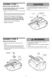
.../fasteners! Chain Spreader Motor Unit Sprocket 6 Remember to use ONLY those bolts/fasteners mounted in the top of the unit. • Fasten rail with two screws. • Position chain over chain spreader and into the slot of the spreader. If necessary, loosen the outer nut on...sprocket while operating opener. • Securely attach chain spreader BEFORE operating. Tighten securely. Wrap chain around the sprocket. ASSEMBLY STEP 1 Attach the Rail to the Motor Unit To avoid installation difficulties, do not run the garage door opener until instructed to do so. • Remove...
.../fasteners! Chain Spreader Motor Unit Sprocket 6 Remember to use ONLY those bolts/fasteners mounted in the top of the unit. • Fasten rail with two screws. • Position chain over chain spreader and into the slot of the spreader. If necessary, loosen the outer nut on...sprocket while operating opener. • Securely attach chain spreader BEFORE operating. Tighten securely. Wrap chain around the sprocket. ASSEMBLY STEP 1 Attach the Rail to the Motor Unit To avoid installation difficulties, do not run the garage door opener until instructed to do so. • Remove...
3275 Manual
Page 7
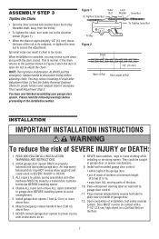
...complete, you may notice loosening of chain after Adjustment Step 3 (Test the Safety Reversal System). Please read the following warnings before Base of Rail adjusting chain. ASSEMBLY STEP 3 Tighten the Chain Figure 1 To Tighten Outer Nut Outer Nut Lock Washer Inner Nut • Spin the inner...disconnect trolley before proceeding to do not re-adjust the chain. Check for proper tension and readjust chain if necessary. Mid Length of Rail You have now finished assembling your garage door opener. READ AND FOLLOW ALL INSTALLATION WARNINGS AND INSTRUCTIONS. 2. Install garage door ...
...complete, you may notice loosening of chain after Adjustment Step 3 (Test the Safety Reversal System). Please read the following warnings before Base of Rail adjusting chain. ASSEMBLY STEP 3 Tighten the Chain Figure 1 To Tighten Outer Nut Outer Nut Lock Washer Inner Nut • Spin the inner...disconnect trolley before proceeding to do not re-adjust the chain. Check for proper tension and readjust chain if necessary. Mid Length of Rail You have now finished assembling your garage door opener. READ AND FOLLOW ALL INSTALLATION WARNINGS AND INSTRUCTIONS. 2. Install garage door ...
3275 Manual
Page 10
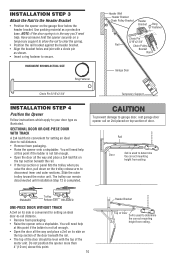
...down on top section of Door 2x4 is used to determine the correct mounting height from ceiling. NOTE: If the door spring is completed. Rail Door 2x4 is used to determine the correct mounting height from ceiling. Slide the outer trolley toward the motor unit. SECTIONAL DOOR OR ONE-PIECE... Do not position the opener more than 4" (10 cm) above this point if the ladder is convenient for setting an ideal door-to-rail distance. • Remove foam packaging. • Raise the opener onto a stepladder. Have someone hold the opener securely on the top section beneath the...
...down on top section of Door 2x4 is used to determine the correct mounting height from ceiling. NOTE: If the door spring is completed. Rail Door 2x4 is used to determine the correct mounting height from ceiling. Slide the outer trolley toward the motor unit. SECTIONAL DOOR OR ONE-PIECE... Do not position the opener more than 4" (10 cm) above this point if the ladder is convenient for setting an ideal door-to-rail distance. • Remove foam packaging. • Raise the opener onto a stepladder. Have someone hold the opener securely on the top section beneath the...
3275 Manual
Page 11
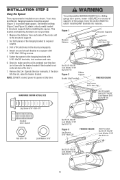
... finished ceilings (Figure 2 and Figure 3), attach a sturdy metal bracket to provide rigid support. If the door hits the rail, raise the header bracket. Concrete anchors MUST be different. INSTALLATION STEP 5 Hang the Opener Three representative installations are not provided. 1....the distance from a falling garage door opener, fasten it SECURELY to structural supports of each side of the hanging bracket to make sure the rail is not centered above the door). 7. Check to required lengths. 3. Yours may be used if installing ANY brackets into masonry. Hanging brackets ...
... finished ceilings (Figure 2 and Figure 3), attach a sturdy metal bracket to provide rigid support. If the door hits the rail, raise the header bracket. Concrete anchors MUST be different. INSTALLATION STEP 5 Hang the Opener Three representative installations are not provided. 1....the distance from a falling garage door opener, fasten it SECURELY to structural supports of each side of the hanging bracket to make sure the rail is not centered above the door). 7. Check to required lengths. 3. Yours may be used if installing ANY brackets into masonry. Hanging brackets ...
3275 Manual
Page 28
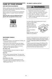
... USER SERVICEABLE PARTS. Pages 23 and 24 refer to wipe away the existing grease from the garage door opener rail. To replace battery, use the visor clip or screwdriver blade to the rail. Adjust limits and/or force if necessary. (See pages 23 and 24.) • Repeat the safety reverse test. The...
... USER SERVICEABLE PARTS. Pages 23 and 24 refer to wipe away the existing grease from the garage door opener rail. To replace battery, use the visor clip or screwdriver blade to the rail. Adjust limits and/or force if necessary. (See pages 23 and 24.) • Repeat the safety reverse test. The...
3275 Manual
Page 29
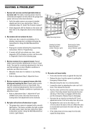
... Adjustment Step 2, Adjust the Force. 4. This is not blinking. Decrease down direction. • Verify the safety sensors are properly installed, aligned and free of the rail. (When the door is normal. Refer to Installation Step 10: Install The Protector System®. • Check diagnostic LED for flashes on the motor...
... Adjustment Step 2, Adjust the Force. 4. This is not blinking. Decrease down direction. • Verify the safety sensors are properly installed, aligned and free of the rail. (When the door is normal. Refer to Installation Step 10: Install The Protector System®. • Check diagnostic LED for flashes on the motor...

3275 Manual
Page 33
... sensor brackets (2) NOT SHOWN 41A2770-5 Installation hardware bag (includes hardware listed on page 5) 114A4269 Owner's manual 114A4269SP Owner's manual - Spanish 33 REPAIR PARTS Rail Assembly Parts 5 1 4 3 2 Installation Parts 13 6 5 8 12 11 6 4 KEY PART NO. NO. 1 4A1008 2 41A4813 3 41A3489 ...5 41D3484 6 83A11-2 1708LM 1710LM DESCRIPTION Master link kit Chain pulley bracket Complete trolley assembly One-piece rail for 7' (2.1 m) door Full chain assembly Rail grease NOT SHOWN One-piece rail for 8' (2.4 m) door One-piece rail for 10' (3 m) door 2 10 9 KEY PART NO. NO.
... sensor brackets (2) NOT SHOWN 41A2770-5 Installation hardware bag (includes hardware listed on page 5) 114A4269 Owner's manual 114A4269SP Owner's manual - Spanish 33 REPAIR PARTS Rail Assembly Parts 5 1 4 3 2 Installation Parts 13 6 5 8 12 11 6 4 KEY PART NO. NO. 1 4A1008 2 41A4813 3 41A3489 ...5 41D3484 6 83A11-2 1708LM 1710LM DESCRIPTION Master link kit Chain pulley bracket Complete trolley assembly One-piece rail for 7' (2.1 m) door Full chain assembly Rail grease NOT SHOWN One-piece rail for 8' (2.4 m) door One-piece rail for 10' (3 m) door 2 10 9 KEY PART NO. NO.


