
Owners Manual
Page 1
® GARAGE DOOR OPENER Models The Chamberlain Group, Inc. 845 Larch Avenue Elmhurst, Illinois 60126-1196 www.liftmaster.com 3130M 1/3 HP For Residential Use Only 3240M 1/2 HP Owner's Manual ■ Please read this manual and the enclosed safety materials carefully! ■ Fasten the manual near the garage door after installation. ■ The door WILL NOT CLOSE unless the Protector System® is connected and properly aligned. ■ Periodic checks of the opener are required to ensure safe operation. ■ The model number label is located on the front panel of your opener.
® GARAGE DOOR OPENER Models The Chamberlain Group, Inc. 845 Larch Avenue Elmhurst, Illinois 60126-1196 www.liftmaster.com 3130M 1/3 HP For Residential Use Only 3240M 1/2 HP Owner's Manual ■ Please read this manual and the enclosed safety materials carefully! ■ Fasten the manual near the garage door after installation. ■ The door WILL NOT CLOSE unless the Protector System® is connected and properly aligned. ■ Periodic checks of the opener are required to ensure safe operation. ■ The model number label is located on the front panel of your opener.
Owners Manual
Page 2
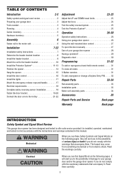
...location 8 Install the header bracket 9 Attach the rail to the header bracket 10 Install the Protector System 11-13 Position the opener 14 Hang the opener 15 Install the door control 16 Install the lights 17 Attach the emergency release rope and handle 17 Electrical requirements 18 Complete ... parts 34 Accessories 35 Repair Parts and Service Back page Warranty Back page INTRODUCTION Safety Symbol and Signal Word Review This garage door opener has been designed and tested to the possibility of serious injury or death if you do not comply with the instructions and warnings...
...location 8 Install the header bracket 9 Attach the rail to the header bracket 10 Install the Protector System 11-13 Position the opener 14 Hang the opener 15 Install the door control 16 Install the lights 17 Attach the emergency release rope and handle 17 Electrical requirements 18 Complete ... parts 34 Accessories 35 Repair Parts and Service Back page Warranty Back page INTRODUCTION Safety Symbol and Signal Word Review This garage door opener has been designed and tested to the possibility of serious injury or death if you do not comply with the instructions and warnings...
Owners Manual
Page 3
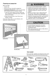
... which are under EXTREME tension. • Disable ALL locks and remove ALL ropes connected to garage door BEFORE installing and operating garage door opener to avoid malfunction and damage. An unbalanced garage door may NOT reverse when required. • NEVER try to loosen, move or adjust ...garage door binds, sticks, or is any ropes connected to garage door. • Complete the following test to see if there is out of the opener, instructions will call a trained door systems technician. Carpenter's Level (optional) 12 Tape Measure Pencil Wire Cutters Drill 3/16", 5/16" and 5/32"...
... which are under EXTREME tension. • Disable ALL locks and remove ALL ropes connected to garage door BEFORE installing and operating garage door opener to avoid malfunction and damage. An unbalanced garage door may NOT reverse when required. • NEVER try to loosen, move or adjust ...garage door binds, sticks, or is any ropes connected to garage door. • Complete the following test to see if there is out of the opener, instructions will call a trained door systems technician. Carpenter's Level (optional) 12 Tape Measure Pencil Wire Cutters Drill 3/16", 5/16" and 5/32"...
Owners Manual
Page 4
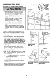
... and bottom of door must not exceed 1/4" (6 mm). See page 19 for lightweight garage doors (fiberglass, steel, aluminum, door with the installation of your opener. Safety Reversing Sensor Safety Reversing Sensor Gap between floor and bottom of door must not exceed 1/4" (6 mm). Survey your garage area to see if...
... and bottom of door must not exceed 1/4" (6 mm). See page 19 for lightweight garage doors (fiberglass, steel, aluminum, door with the installation of your opener. Safety Reversing Sensor Safety Reversing Sensor Gap between floor and bottom of door must not exceed 1/4" (6 mm). Survey your garage area to see if...

Owners Manual
Page 5
... 6-32x1" (2) Self-Threading Screw 1/4"-14x5/8" (2) Insulated Staples (30) Ring Fastener (3) Drywall Anchors (2) Carriage Bolt 1/4"-20x1/2" (2) Wing Nut 1/4"-20 (2) Rope Handle 5 Carton Inventory Your garage door opener is packaged in the foam. Parts may be stuck in two cartons which contain the motor unit and all parts illustrated below .
... 6-32x1" (2) Self-Threading Screw 1/4"-14x5/8" (2) Insulated Staples (30) Ring Fastener (3) Drywall Anchors (2) Carriage Bolt 1/4"-20x1/2" (2) Wing Nut 1/4"-20 (2) Rope Handle 5 Carton Inventory Your garage door opener is packaged in the foam. Parts may be stuck in two cartons which contain the motor unit and all parts illustrated below .
Owners Manual
Page 6
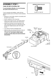
... 6 Rack To motor unit ASSEMBLY STEP 1 Fasten the Rail to the Motor Unit To avoid installation difficulties, do not run the garage door opener until the coupling fits securely over the rail sprocket. • Slide the rail through the motor unit bracket until instructed to do so. Remove...
... 6 Rack To motor unit ASSEMBLY STEP 1 Fasten the Rail to the Motor Unit To avoid installation difficulties, do not run the garage door opener until the coupling fits securely over the rail sprocket. • Slide the rail through the motor unit bracket until instructed to do so. Remove...
Owners Manual
Page 7
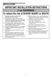
... the floor. 7 Install wall-mounted garage door control: • within reach, but at least 6 feet (1.83 m) above floor. 6. Install garage door opener 7 feet (2.1 m) or more above the fl oor and avoiding contact with a 1-1/2" (3.8 cm) high object (or a 2x4 laid flat minimum height of...; away from ALL moving parts of garage door. 12. Disable ALL locks and remove ALL ropes connected to garage door BEFORE installing opener to do so. 8. Door MUST reverse on contact with vehicles to cables, spring assemblies and other hardware MUST be caught in SEVERE...
... the floor. 7 Install wall-mounted garage door control: • within reach, but at least 6 feet (1.83 m) above floor. 6. Install garage door opener 7 feet (2.1 m) or more above the fl oor and avoiding contact with a 1-1/2" (3.8 cm) high object (or a 2x4 laid flat minimum height of...; away from ALL moving parts of garage door. 12. Disable ALL locks and remove ALL ropes connected to garage door BEFORE installing opener to do so. 8. Door MUST reverse on contact with vehicles to cables, spring assemblies and other hardware MUST be caught in SEVERE...
Owners Manual
Page 8
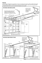
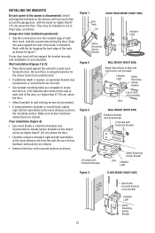
... header wall above the high point: • 3" (7.5 cm) above the high point for sectional door and one -piece door without track: jamb hardware pivot hardware 8 Open your door to the highest point of Travel Pivot One-piece door without track: One-piece door without track. NOTE: If the total number of...
... header wall above the high point: • 3" (7.5 cm) above the high point for sectional door and one -piece door without track: jamb hardware pivot hardware 8 Open your door to the highest point of Travel Pivot One-piece door without track: One-piece door without track. NOTE: If the total number of...
Owners Manual
Page 10
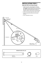
... spring is in the way you'll need help. Garage Door Rail Ring Fastener Header Bracket Clevis Pin 5/16"x2-3/4" Spacer Rail Bracket Rail Spacer Opener Carton or Temporary Support HARDWARE SHOWN ACTUAL SIZE Clevis Pin 5/16"x2-3/4" Ring Fastener 10 Spacer Use packing material as shown. • Insert a ring fastener... join with a clevis pin as a protective base. Header Wall Header Bracket Rail Bracket INSTALLATION STEP 3 Attach the Rail to the Header Bracket • Position the opener on a temporary support to allow the rail to secure.
... spring is in the way you'll need help. Garage Door Rail Ring Fastener Header Bracket Clevis Pin 5/16"x2-3/4" Spacer Rail Bracket Rail Spacer Opener Carton or Temporary Support HARDWARE SHOWN ACTUAL SIZE Clevis Pin 5/16"x2-3/4" Ring Fastener 10 Spacer Use packing material as shown. • Insert a ring fastener... join with a clevis pin as a protective base. Header Wall Header Bracket Rail Bracket INSTALLATION STEP 3 Attach the Rail to the Header Bracket • Position the opener on a temporary support to allow the rail to secure.

Owners Manual
Page 11
...64258;oor. above garage floor. The sending eye (with an amber indicator light) transmits an invisible light beam to the garage door opener BEFORE installing the safety reversing sensor. Be sure power is NOT connected to the receiving eye (with a green indicator light). The invisible light ...unobstructed. Safety Reversing Sensor Invisible Light Beam 6" (15 cm) max. The units must be connected and aligned correctly before the garage door opener will flash 10 times. To prevent SERIOUS INJURY or DEATH from inside the garage so that the sending and receiving eyes face each...
...64258;oor. above garage floor. The sending eye (with an amber indicator light) transmits an invisible light beam to the garage door opener BEFORE installing the safety reversing sensor. Be sure power is NOT connected to the receiving eye (with a green indicator light). The invisible light ...unobstructed. Safety Reversing Sensor Invisible Light Beam 6" (15 cm) max. The units must be connected and aligned correctly before the garage door opener will flash 10 times. To prevent SERIOUS INJURY or DEATH from inside the garage so that the sending and receiving eyes face each...
Owners Manual
Page 12
... sure there is enough clearance for the sensor beam to be unobstructed. • If additional depth is needed, an extension bracket (see Accessories) to the opener is recommended. Install and align the brackets so the sensors will not support the bracket securely, wall installation is disconnected. Make sure all door hardware...
... sure there is enough clearance for the sensor beam to be unobstructed. • If additional depth is needed, an extension bracket (see Accessories) to the opener is recommended. Install and align the brackets so the sensors will not support the bracket securely, wall installation is disconnected. Make sure all door hardware...
Owners Manual
Page 14
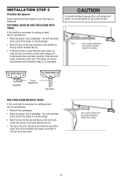
... convenient for setting an ideal door-to your door type as illustrated. Top of Door Door 2x4 is used to garage door, rest garage door opener rail on 2x4 placed on its side is completed. You will need help at this point. You will need help at is not tall enough.... • Open the door all the way and place a 2x4 on top section of the motor unit. The trolley can remain disconnected until Installation Step 13 is...
... convenient for setting an ideal door-to your door type as illustrated. Top of Door Door 2x4 is used to garage door, rest garage door opener rail on 2x4 placed on its side is completed. You will need help at this point. You will need help at is not tall enough.... • Open the door all the way and place a 2x4 on top section of the motor unit. The trolley can remain disconnected until Installation Step 13 is...
Owners Manual
Page 15
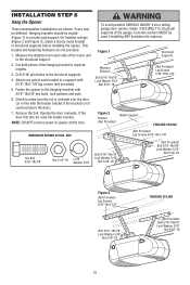
... brackets with 5/16"-18x1-7/8" lag screws (not provided). 5. Concrete anchors MUST be different. Measure the distance from a falling garage door opener, fasten it SECURELY to structural supports of the motor unit to required lengths. 3. If the door hits the rail, raise the header ...above the door). 7. Yours may be used if installing ANY brackets into masonry. Check to opener at this time. Hanging brackets should be angled (Figure 1) to structural supports before installing the opener. Operate the door manually. On finished ceilings (Figure 2 and Figure 3), attach a...
... brackets with 5/16"-18x1-7/8" lag screws (not provided). 5. Concrete anchors MUST be different. Measure the distance from a falling garage door opener, fasten it SECURELY to structural supports of the motor unit to required lengths. 3. If the door hits the rail, raise the header ...above the door). 7. Yours may be used if installing ANY brackets into masonry. Check to opener at this time. Hanging brackets should be angled (Figure 1) to structural supports before installing the opener. Operate the door manually. On finished ceilings (Figure 2 and Figure 3), attach a...
Owners Manual
Page 16
...6ABx1-1/4" Screw Multi-Function (pre-wired) Screw 6-32x1" Figure 1 STANDARD INSTALLATION Figure 2 PRE-WIRED INSTALLATION a staple, creating a short or open position but will travel . • ALWAYS keep garage door in several places. To Replace Insert Bottom Tabs First Figure 3 Terminal Screws To ...insulation from moving parts of door. 1. Multi-function: Remove white cover by color: white wire to white, white/red wire to the opener, twist same color wires together. For pre-wired installations (as follows: HARDWARE SHOWN ACTUAL SIZE • Drill and install bottom screw, allowing...
...6ABx1-1/4" Screw Multi-Function (pre-wired) Screw 6-32x1" Figure 1 STANDARD INSTALLATION Figure 2 PRE-WIRED INSTALLATION a staple, creating a short or open position but will travel . • ALWAYS keep garage door in several places. To Replace Insert Bottom Tabs First Figure 3 Terminal Screws To ...insulation from moving parts of door. 1. Multi-function: Remove white cover by color: white wire to white, white/red wire to the opener, twist same color wires together. For pre-wired installations (as follows: HARDWARE SHOWN ACTUAL SIZE • Drill and install bottom screw, allowing...
Owners Manual
Page 17
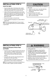
... door: • If possible, use emergency release handle to prevent slipping. • Thread the other end of the rope through the hole in an open or closed. NOTE: If it is 6 feet (1.83 m) above the floor. Trolley Trolley Release Arm Emergency Release Handle NOTICE Overhand Knot 17 ... rotate lens back and downward until the lens hinge is CLOSED. Then the lights will turn OFF. • Reverse the procedure to pull door open door falling rapidly and/or unexpectedly. • NEVER use emergency release handle unless garage doorway is clear of the outer trolley. • Adjust ...
... door: • If possible, use emergency release handle to prevent slipping. • Thread the other end of the rope through the hole in an open or closed. NOTE: If it is 6 feet (1.83 m) above the floor. Trolley Trolley Release Arm Emergency Release Handle NOTICE Overhand Knot 17 ... rotate lens back and downward until the lens hinge is CLOSED. Then the lights will turn OFF. • Reverse the procedure to pull door open door falling rapidly and/or unexpectedly. • NEVER use emergency release handle unless garage doorway is clear of the outer trolley. • Adjust ...

Owners Manual
Page 18
... heard.) See page 11. 18 To prevent possible SERIOUS INJURY or DEATH from electrocution or fire: • Be sure power is already open wire to establish permanent wiring connection. • Garage door installation and wiring MUST be grounded. • Reinstall the cover. This plug will reverse...hole in ANY way to install the proper outlet. INSTALLATION STEP 10 Electrical Requirements To avoid installation difficulties, do not run the opener at this time. To reduce the risk of electric shock, your local code, refer to the green ground screw. To avoid installation dif...
... heard.) See page 11. 18 To prevent possible SERIOUS INJURY or DEATH from electrocution or fire: • Be sure power is already open wire to establish permanent wiring connection. • Garage door installation and wiring MUST be grounded. • Reinstall the cover. This plug will reverse...hole in ANY way to install the proper outlet. INSTALLATION STEP 10 Electrical Requirements To avoid installation difficulties, do not run the opener at this time. To reduce the risk of electric shock, your local code, refer to the green ground screw. To avoid installation dif...
Owners Manual
Page 19
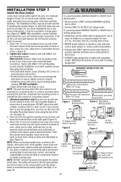
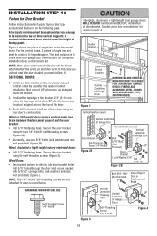
... (Figure 2A). • Alternately, use on the following page. Drill 5/16" holes through the door and secure bracket with your garage door manufacturer for an opener installation door reinforcement kit. For the vertical brace, 2 pieces of the door. 3. Center the door bracket on your door's construction: Metal or light weight doors...
... (Figure 2A). • Alternately, use on the following page. Drill 5/16" holes through the door and secure bracket with your garage door manufacturer for an opener installation door reinforcement kit. For the vertical brace, 2 pieces of the door. 3. Center the door bracket on your door's construction: Metal or light weight doors...
Owners Manual
Page 21
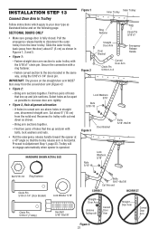
... to trolley with bolts, lock washers and nuts. • Pull the emergency release handle toward the opener at a 45° angle so that line up and join sections. Trolley will re-engage automatically when opener is fully closed. INSTALLATION STEP 13 Connect Door Arm to Trolley Follow instructions which apply to your...
... to trolley with bolts, lock washers and nuts. • Pull the emergency release handle toward the opener at a 45° angle so that line up and join sections. Trolley will re-engage automatically when opener is fully closed. INSTALLATION STEP 13 Connect Door Arm to Trolley Follow instructions which apply to your...
Owners Manual
Page 22
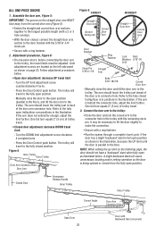
...arm to the trolley. It may be adjusted. Limit adjustment screws are located on the straight door arm MUST face away from the fully open position. - The trolley will cause unnecessary bucking and/or jerking operation as shown on the following page, the door should touch the trolley...the straight door arm section to the door bracket with the 5/16"x1-1/4" clevis pin. • Secure with a ring fastener. • Run the opener through a complete travel limits must be necessary to lift the door slightly to the connector hole in the trolley with Backward Slant (Incorrect) If the...
...arm to the trolley. It may be adjusted. Limit adjustment screws are located on the straight door arm MUST face away from the fully open position. - The trolley will cause unnecessary bucking and/or jerking operation as shown on the following page, the door should touch the trolley...the straight door arm section to the door bracket with the 5/16"x1-1/4" clevis pin. • Secure with a ring fastener. • Run the opener through a complete travel limits must be necessary to lift the door slightly to the connector hole in the trolley with Backward Slant (Incorrect) If the...
Owners Manual
Page 23
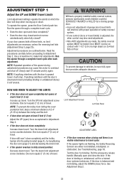
...; If one control (force or travel cycle after each adjustment. Read the procedures carefully before proceeding to travel cycle: If the opener lights are flashing, the Safety Reversing Sensors are made, the safety reversal system MUST be tested. Door MUST reverse on contact... binding: Pull the emergency release handle. NOTE: To prevent the trolley from hitting the cover protection bolt, keep a minimum distance of the opener during adjustment procedures may also need adjustment. • After ANY adjustments are either not installed, misaligned, or obstructed. One turn equals 2"...
...; If one control (force or travel cycle after each adjustment. Read the procedures carefully before proceeding to travel cycle: If the opener lights are flashing, the Safety Reversing Sensors are made, the safety reversal system MUST be tested. Door MUST reverse on contact... binding: Pull the emergency release handle. NOTE: To prevent the trolley from hitting the cover protection bolt, keep a minimum distance of the opener during adjustment procedures may also need adjustment. • After ANY adjustments are either not installed, misaligned, or obstructed. One turn equals 2"...


