
Troubleshooting Guide
Page 1
... tested and approved USB flash memory devices, see our Lexmark Web site at www.lexmark.com. The specified tray is full Remove the stack of your print job by any switch or breaker. • The printer is not plugged into any surge protectors, uninterrupted power supplies, or extension cords. • Other electrical equipment plugged...
... tested and approved USB flash memory devices, see our Lexmark Web site at www.lexmark.com. The specified tray is full Remove the stack of your print job by any switch or breaker. • The printer is not plugged into any surge protectors, uninterrupted power supplies, or extension cords. • Other electrical equipment plugged...

User's Guide
Page 124
... or breaker. • The MFP is not plugged into any surge protectors, uninterrupted power supplies, or extension cords. • Other electrical equipment plugged into the outlet is working. • The MFP is turned on. • The MFP cable is available on our Lexmark Web site at least 10 seconds..., and then turn the MFP off and back on ....
... or breaker. • The MFP is not plugged into any surge protectors, uninterrupted power supplies, or extension cords. • Other electrical equipment plugged into the outlet is working. • The MFP is turned on. • The MFP cable is available on our Lexmark Web site at least 10 seconds..., and then turn the MFP off and back on ....

Service Manual
Page 8
... assembly removal 4-61 Operator panel right cover assembly removal 4-64 Touchscreen bezel removal 4-66 LCD touchscreen removal-models X644e and X646e 4-67 LCD touchscreen removal-model X642e 4-69 Multipurpose feeder/lower front cover assembly removal 4-71 Left cover handle holder removal ... Integrated tray autocompensator pick roll assembly removal 4-105 Interface card assembly removal 4-107 LCD inverter card assembly removal 4-108 Low voltage power supply removal 4-109 Main fan removal 4-111 Main drive assembly removal 4-113 Modem removal 4-115 MPF arm assembly removal 4-116 MPF...
... assembly removal 4-61 Operator panel right cover assembly removal 4-64 Touchscreen bezel removal 4-66 LCD touchscreen removal-models X644e and X646e 4-67 LCD touchscreen removal-model X642e 4-69 Multipurpose feeder/lower front cover assembly removal 4-71 Left cover handle holder removal ... Integrated tray autocompensator pick roll assembly removal 4-105 Interface card assembly removal 4-107 LCD inverter card assembly removal 4-108 Low voltage power supply removal 4-109 Main fan removal 4-111 Main drive assembly removal 4-113 Modem removal 4-115 MPF arm assembly removal 4-116 MPF...
Service Manual
Page 9
... connections 5-1 Locations 5-1 Sensors-flatbed 5-1 Sensors-ADF 5-2 Connections 5-3 System board 5-3 Autoconnect 5-8 Fuser board 5-9 High voltage power supply 5-9 Interface card 5-10 USB card 5-10 Low voltage power supply 5-11 Operator panel card (UICC #1)-model X642e 5-12 Operator panel card (UICC #1)-models X644e/X646e 5-14 LCD inverter board (IUCC #2 5-16 Scanner control card 5-17 Motor driver board 5-23...
... connections 5-1 Locations 5-1 Sensors-flatbed 5-1 Sensors-ADF 5-2 Connections 5-3 System board 5-3 Autoconnect 5-8 Fuser board 5-9 High voltage power supply 5-9 Interface card 5-10 USB card 5-10 Low voltage power supply 5-11 Operator panel card (UICC #1)-model X642e 5-12 Operator panel card (UICC #1)-models X644e/X646e 5-14 LCD inverter board (IUCC #2 5-16 Scanner control card 5-17 Motor driver board 5-23...
Service Manual
Page 10
... 18: Drives-Main drive and developer drive 7-32 Assembly 19: Hot roll fuser 7-34 Assembly 20: Transfer/charging 7-36 Assembly 21: Electronics-power supplies 7-38 Assembly 22: Electronics-card assemblies 7-40 Assembly 23: Electronics-shields 7-42 Assembly 24: Cabling diagram 1 7-43 Assembly 25: Cabling diagram...7-44 Assembly 26: Cabling diagram 3 7-45 Assembly 27: Cabling diagram 4-model X642e 7-46 Assembly 28: Cabling diagram 4-models X644e/X646e 7-48 Assembly 29: Cabling diagram 5 7-50 Assembly 30: Cabling diagram 6-model X642e 7-52 Assembly 31: Cabling diagram 6-models X644e...
... 18: Drives-Main drive and developer drive 7-32 Assembly 19: Hot roll fuser 7-34 Assembly 20: Transfer/charging 7-36 Assembly 21: Electronics-power supplies 7-38 Assembly 22: Electronics-card assemblies 7-40 Assembly 23: Electronics-shields 7-42 Assembly 24: Cabling diagram 1 7-43 Assembly 25: Cabling diagram...7-44 Assembly 26: Cabling diagram 3 7-45 Assembly 27: Cabling diagram 4-model X642e 7-46 Assembly 28: Cabling diagram 4-models X644e/X646e 7-48 Assembly 29: Cabling diagram 5 7-50 Assembly 30: Cabling diagram 6-model X642e 7-52 Assembly 31: Cabling diagram 6-models X644e...
Service Manual
Page 38
...-xxx Acronyms ADF AIO CCD CRU DIMM DRAM EP EPROM ESD FRU GB HCIT HVPS ITC LASER LCD LED LES LVPS MDC MFP MPF NVRAM OPT PC PIN PJL POR POST PP PWM RIP SCC SDRAM SIMM UAT USB V ac V dc Automatic Document ... Field Replaceable Unit Gigabyte High-Capacity Input Tray High Voltage Power Supply Internal Tray Card Light Amplification by Stimulated Emission of Radiation Liquid Crystal Display Light-Emitting Diode Lexmark Embedded Solution (applications) Low Voltage Power Supply Motor Driver Control Multifunction Printer Multipurpose Feeder Nonvolatile Random Access Memory Optical Sensor Photoconductor ...
...-xxx Acronyms ADF AIO CCD CRU DIMM DRAM EP EPROM ESD FRU GB HCIT HVPS ITC LASER LCD LED LES LVPS MDC MFP MPF NVRAM OPT PC PIN PJL POR POST PP PWM RIP SCC SDRAM SIMM UAT USB V ac V dc Automatic Document ... Field Replaceable Unit Gigabyte High-Capacity Input Tray High Voltage Power Supply Internal Tray Card Light Amplification by Stimulated Emission of Radiation Liquid Crystal Display Light-Emitting Diode Lexmark Embedded Solution (applications) Low Voltage Power Supply Motor Driver Control Multifunction Printer Multipurpose Feeder Nonvolatile Random Access Memory Optical Sensor Photoconductor ...
Service Manual
Page 71
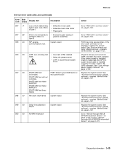
... page 2-121. See "Low voltage power supply removal" on page 2-153. Replace the system board. or go to "Main drive service check" on page 4-109. Go to "950.30 through 950.29 EPROM mismatch failure" on page 4-131. See "System board and inner shield removal -models X644e/X646e" on page 2-153. System board...
... page 2-121. See "Low voltage power supply removal" on page 2-153. Replace the system board. or go to "Main drive service check" on page 4-109. Go to "950.30 through 950.29 EPROM mismatch failure" on page 4-131. See "System board and inner shield removal -models X644e/X646e" on page 2-153. System board...
Service Manual
Page 164
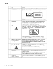
... approximately +5 V dc. 6 Features or option installed on the interface card assembly 7 LVPS fuse F1 (primary power) If the voltage is incorrect, replace the LVPS assembly. Remove one option/feature at the +5 V dc test... the printer system board and to step 10. 2-126 Service Manual See "Low voltage power supply removal" on the LVPS. Check to the system board and each cable connected to make sure... the LVPS cable is located. See "Low voltage power supply removal" on page 4-109 Warning: Observe all the ESD precautions and turn the printer ...
... approximately +5 V dc. 6 Features or option installed on the interface card assembly 7 LVPS fuse F1 (primary power) If the voltage is incorrect, replace the LVPS assembly. Remove one option/feature at the +5 V dc test... the printer system board and to step 10. 2-126 Service Manual See "Low voltage power supply removal" on the LVPS. Check to the system board and each cable connected to make sure... the LVPS cable is located. See "Low voltage power supply removal" on page 4-109 Warning: Observe all the ESD precautions and turn the printer ...

Service Manual
Page 170
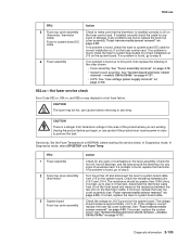
... cable is installed correctly to the fuser top cover assembly. If incorrect, install correctly; If incorrect, replace the LVPS assembly (see "Low voltage power supply removal" on page 4-109); If incorrect, inform the customer; It may be necessary to remove the redrive assembly to observe the lamp turning on... and off . if correct, go to perform the task. Disconnect the LVPS to access CN1 on the LVPS board (see "Low voltage power supply removal" on page 4-109). Unplug the product before starting this service check. In Diagnostics mode, select EP SETUP, and Fuser Temp. Some...
... cable is installed correctly to the fuser top cover assembly. If incorrect, install correctly; If incorrect, replace the LVPS assembly (see "Low voltage power supply removal" on page 4-109); If incorrect, inform the customer; It may be necessary to remove the redrive assembly to observe the lamp turning on... and off . if correct, go to perform the task. Disconnect the LVPS to access CN1 on the LVPS board (see "Low voltage power supply removal" on page 4-109). Unplug the product before starting this service check. In Diagnostics mode, select EP SETUP, and Fuser Temp. Some...

Service Manual
Page 171
... of the LPVS to CN2 on the LVPS. If correct, replace the LVPS to system board cable. If any signs of damage. See "Low voltage power supply removal" on page 4-79. • System board assembly. See "Fuser assembly removal" on page 4-109. • System board assembly. 7002-xxx FRU 4 Fuser lamp Fuser... the fuser to fuser lamp AC cable. See "System board and inner shield removal -models X644e/X646e" on page 4-109. If the voltage is found up to this point, then replace the following FRUs in the power cord, turn the printer on page 4-131. • LVPS to fuser AC cable; See "System...
... of the LPVS to CN2 on the LVPS. If correct, replace the LVPS to system board cable. If any signs of damage. See "Low voltage power supply removal" on page 4-79. • System board assembly. See "Fuser assembly removal" on page 4-109. • System board assembly. 7002-xxx FRU 4 Fuser lamp Fuser... the fuser to fuser lamp AC cable. See "System board and inner shield removal -models X644e/X646e" on page 4-109. If the voltage is found up to this point, then replace the following FRUs in the power cord, turn the printer on page 4-131. • LVPS to fuser AC cable; See "System...

Service Manual
Page 172
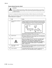
... from hazardous voltage in the area of the LVPS to access CN1 on the LVPS board (see the connector locations at "Low voltage power supply" on the LVPS board. Check the AC line voltage to check the voltage between CN-1 and CN-3 on page 5-11). if correct... cable. If correct, replace the LVPS to step 4. See "Low voltage power supply removal" on page 4-109); CAUTION: When taking measurements for AC power, observe all safety precautions. If incorrect, replace the LVPS assembly (see "Low voltage power supply removal" on page 4-109. if correct, go to fuser AC cable; Note...
... from hazardous voltage in the area of the LVPS to access CN1 on the LVPS board (see the connector locations at "Low voltage power supply" on the LVPS board. Check the AC line voltage to check the voltage between CN-1 and CN-3 on page 5-11). if correct... cable. If correct, replace the LVPS to step 4. See "Low voltage power supply removal" on page 4-109); CAUTION: When taking measurements for AC power, observe all safety precautions. If incorrect, replace the LVPS assembly (see "Low voltage power supply removal" on page 4-109. if correct, go to fuser AC cable; Note...
Service Manual
Page 173
...page 4-131. • LVPS. If installed correctly check the cable for any problems are working. See "System board and inner shield removal -models X644e/X646e" on page 4-131. In Diagnostics mode, In Diagnostics mode, select EP SETUP, and Fuser Temp. If no problem is found, check the fuser to...Error Code 923.xx, 924.xx, and 925.xx may be greater than 100K ohms. If correct, go to perform the task. See "Low voltage power supply removal" on the system board. If incorrect, replace the system board. See "Fuser assembly removal" on page 4-88); Turn the printer off and ...
...page 4-131. • LVPS. If installed correctly check the cable for any problems are working. See "System board and inner shield removal -models X644e/X646e" on page 4-131. In Diagnostics mode, In Diagnostics mode, select EP SETUP, and Fuser Temp. If no problem is found, check the fuser to...Error Code 923.xx, 924.xx, and 925.xx may be greater than 100K ohms. If correct, go to perform the task. See "Low voltage power supply removal" on the system board. If incorrect, replace the system board. See "Fuser assembly removal" on page 4-88); Turn the printer off and ...
Service Manual
Page 178
...-18 on the system board. The voltage should measure approximately +50 V dc. The voltage should measure approximately +50 V dc. See "Low voltage power supply removal" on page 4-2. Make sure the cable is connected correctly, go to perform the task. If no problems were found in order to step 4.... assembly. See "System board and inner shield removal-model X642e" on page 4-130 or "System board and inner shield removal -models X644e/ X646e" on page 4-79. 2-140 Service Manual If the cable is connected properly to system board cable 5 Fuser assembly The resistance measures between J4...
...-18 on the system board. The voltage should measure approximately +50 V dc. The voltage should measure approximately +50 V dc. See "Low voltage power supply removal" on page 4-2. Make sure the cable is connected correctly, go to perform the task. If no problems were found in order to step 4.... assembly. See "System board and inner shield removal-model X642e" on page 4-130 or "System board and inner shield removal -models X644e/ X646e" on page 4-79. 2-140 Service Manual If the cable is connected properly to system board cable 5 Fuser assembly The resistance measures between J4...

Service Manual
Page 359
... 4-58. 3. Disconnect the HVPS cable from the transformer on the HVPS. Unplug the product before you begin, or use caution if the product must receive power in the area of the product where you are working. Remove the inner paper deflector. Remove the right side cover. A 4. See "Printer right cover removal..." on page 4-101. 2. Disconnect the transfer roll cable (B) from hazardous voltage in order to perform the task. 1. 7002-xxx High voltage power supply removal CAUTION There is a danger from the HVPS board.
... 4-58. 3. Disconnect the HVPS cable from the transformer on the HVPS. Unplug the product before you begin, or use caution if the product must receive power in the area of the product where you are working. Remove the inner paper deflector. Remove the right side cover. A 4. See "Printer right cover removal..." on page 4-101. 2. Disconnect the transfer roll cable (B) from hazardous voltage in order to perform the task. 1. 7002-xxx High voltage power supply removal CAUTION There is a danger from the HVPS board.

Service Manual
Page 369
... the LVPS mounting screws (A) from the rear of the center pan. 5. Repair information 4-109 See "Redrive assembly removal" on the LVPS card connector (C). Low voltage power supply removal CAUTION Unplug the printer before you begin. 7002-xxx 1.
... the LVPS mounting screws (A) from the rear of the center pan. 5. Repair information 4-109 See "Redrive assembly removal" on the LVPS card connector (C). Low voltage power supply removal CAUTION Unplug the printer before you begin. 7002-xxx 1.

Service Manual
Page 370
Do not use excessive force in the removal. 7. Pull the LVPS assembly far enough out from the printer. Warning: The LVPS assembly may be difficult to remove from the right side of the printer to disconnect the fuser to LVPS AC lamp cable (D). Remove the low voltage power supply. 4-110 Service Manual 7002-xxx 6.
Do not use excessive force in the removal. 7. Pull the LVPS assembly far enough out from the printer. Warning: The LVPS assembly may be difficult to remove from the right side of the printer to disconnect the fuser to LVPS AC lamp cable (D). Remove the low voltage power supply. 4-110 Service Manual 7002-xxx 6.

Service Manual
Page 409
Fuser board Fuser Board (not a FRU) High voltage power supply Connector CN1 System board Connectors J1-System board J2-Narrow media sensor J3-N/A J4-Solenoid J5-Exit sensor J6-Thermistor 7002-xxx CN no. 1 2 3 4 5 6 7 8 Signal Developer PWM +24 V dc Return Charge PWM +24 V dc IN TX PWM TX Enable TX CUR PWM SVRO OUT Locations and connections 5-9
Fuser board Fuser Board (not a FRU) High voltage power supply Connector CN1 System board Connectors J1-System board J2-Narrow media sensor J3-N/A J4-Solenoid J5-Exit sensor J6-Thermistor 7002-xxx CN no. 1 2 3 4 5 6 7 8 Signal Developer PWM +24 V dc Return Charge PWM +24 V dc IN TX PWM TX Enable TX CUR PWM SVRO OUT Locations and connections 5-9

Service Manual
Page 411
Low voltage power supply Connector CN1 Fuser lamp AC CN2 DC output 7002-xxx CN pin no. 1 2 3 Signal AC fuser lamp Not used AC fuser lamp 1 +5 V dc 2 +5 V dc 3 Ground 4 Ground 5 Ground 6 Ground 7 +24 V dc 8 +24 V dc 9 Heat on 10 +5 V dc 11 +5 V dc 12 Ground 13 Ground 14 Ground 15 Ground 16 +24 V dc 17 ZC Out* 18 +42 V dc Locations and connections 5-11
Low voltage power supply Connector CN1 Fuser lamp AC CN2 DC output 7002-xxx CN pin no. 1 2 3 Signal AC fuser lamp Not used AC fuser lamp 1 +5 V dc 2 +5 V dc 3 Ground 4 Ground 5 Ground 6 Ground 7 +24 V dc 8 +24 V dc 9 Heat on 10 +5 V dc 11 +5 V dc 12 Ground 13 Ground 14 Ground 15 Ground 16 +24 V dc 17 ZC Out* 18 +42 V dc Locations and connections 5-11
Service Manual
Page 433
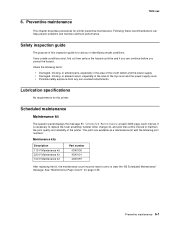
If any non-Lexmark attachments. Lubrication specifications No requirements for printer preventive maintenance. See "Maintenance Page Count" on /off switch and the power supply. • Damaged, missing, or altered covers, especially in identifying unsafe conditions. Scheduled maintenance Maintenance kit The operator panel ... interval to aid you correct the hazard. It is to maintain the print quality and reliability of the top cover and the power supply cover. • Possible safety exposure from any unsafe conditions exist, find out how serious the hazard could be reset to zero...
If any non-Lexmark attachments. Lubrication specifications No requirements for printer preventive maintenance. See "Maintenance Page Count" on /off switch and the power supply. • Damaged, missing, or altered covers, especially in identifying unsafe conditions. Scheduled maintenance Maintenance kit The operator panel ... interval to aid you correct the hazard. It is to maintain the print quality and reliability of the top cover and the power supply cover. • Possible safety exposure from any unsafe conditions exist, find out how serious the hazard could be reset to zero...

Service Manual
Page 474
7002-xxx Assembly 21: Electronics-power supplies 7-38 Service Manual
7002-xxx Assembly 21: Electronics-power supplies 7-38 Service Manual


