
Menus and Messages
Page 111
...function. Examples of these are: E-mail turned off by system administrator. The MFP detects after powering on Cable Unplugged that the back side scanner cable is unplugged. 298.02 Scanner Missing - Fax turned off by administrator. 111 The message appears when any menu item is disabled. ..., and then the previous screen appears. TCP/IP turned off . 2 Plug the back side scanner cable into its connector. 3 Turn the MFP on. Action 1 Turn the MFP off. 2 Plug the front side scanner cable into its connector. 3 Turn the MFP on. 1 Turn the MFP off by system administrator....
...function. Examples of these are: E-mail turned off by system administrator. The MFP detects after powering on Cable Unplugged that the back side scanner cable is unplugged. 298.02 Scanner Missing - Fax turned off by administrator. 111 The message appears when any menu item is disabled. ..., and then the previous screen appears. TCP/IP turned off . 2 Plug the back side scanner cable into its connector. 3 Turn the MFP on. Action 1 Turn the MFP off. 2 Plug the front side scanner cable into its connector. 3 Turn the MFP on. 1 Turn the MFP off by system administrator....

Menus and Messages
Page 117
...page [n] 95 Sending page [n] 95 Set clock 95 Waiting for sending 100 Reattach envelope feeder 100 Remove paper from the scanner 110 298.01 Scanner Missing - Cable Unplugged 111 30.yy Invalid refill, change cartridge 101 31.yy Replace defective print cartridge 102 32.yy Replace unsupported print... 102 35 Insufficient memory to support Resource Save feature 102 37 Insufficient memory for Flash Memory Defragment operation 102 37 Insufficient memory to exit the scanner. 98 Insert tray [x] 98 Install duplex 98 Install envelope feeder 99 Install tray [x] 99 Load [src] with [Custom String] 100 Load...
...page [n] 95 Sending page [n] 95 Set clock 95 Waiting for sending 100 Reattach envelope feeder 100 Remove paper from the scanner 110 298.01 Scanner Missing - Cable Unplugged 111 30.yy Invalid refill, change cartridge 101 31.yy Replace defective print cartridge 102 32.yy Replace unsupported print... 102 35 Insufficient memory to support Resource Save feature 102 37 Insufficient memory for Flash Memory Defragment operation 102 37 Insufficient memory to exit the scanner. 98 Insert tray [x] 98 Install duplex 98 Install envelope feeder 99 Install tray [x] 99 Load [src] with [Custom String] 100 Load...

Service Manual
Page 4
7002-xxx Scanner-scan quality 2-11 High-capacity feeder (2000-sheet) symptoms 2-11 Paper tray symptoms 2-12 Duplex option symptoms 2-12 Envelope feeder symptoms 2-12 Messages and error ... ADF paper width sensor service check-models X644e/X646e 2-123 Charge roll service check 2-123 Cover closed sensors service check-flatbed 2-124 Cover closed switch/cable service check-printer 2-125 Dead machine service check 2-125 Duplex option service check 2-127 Envelope feeder service check 2-129 Flatbed size sensor service check 2-131...
7002-xxx Scanner-scan quality 2-11 High-capacity feeder (2000-sheet) symptoms 2-11 Paper tray symptoms 2-12 Duplex option symptoms 2-12 Envelope feeder symptoms 2-12 Messages and error ... ADF paper width sensor service check-models X644e/X646e 2-123 Charge roll service check 2-123 Cover closed sensors service check-flatbed 2-124 Cover closed switch/cable service check-printer 2-125 Dead machine service check 2-125 Duplex option service check 2-127 Envelope feeder service check 2-129 Flatbed size sensor service check 2-131...
Service Manual
Page 7
...35 Exit Configuration Menu 3-35 Theory 3-36 Autocompensator operation 3-36 Autoconnect system, paper tray options, envelope feeder-electrical 3-37 Autoconnect cabling and connectors 3-37 Duplex Option 3-37 Option microcode 3-37 Paper feed jams 3-38 Identifying jams 3-38 Access doors and trays 3-... Door 3-47 23x Paper Jam Open Duplex Rear Door 3-48 Clearing ADF jams 3-49 290, 291, 292, and 294 Scanner Jams 3-49 Repair information 4-1 Handling ESD-sensitive parts 4-1 Adjustment procedures 4-2 Fuser solenoid adjustment 4-2 Gap adjustment 4-2 Printhead assembly adjustment-printer...
...35 Exit Configuration Menu 3-35 Theory 3-36 Autocompensator operation 3-36 Autoconnect system, paper tray options, envelope feeder-electrical 3-37 Autoconnect cabling and connectors 3-37 Duplex Option 3-37 Option microcode 3-37 Paper feed jams 3-38 Identifying jams 3-38 Access doors and trays 3-... Door 3-47 23x Paper Jam Open Duplex Rear Door 3-48 Clearing ADF jams 3-49 290, 291, 292, and 294 Scanner Jams 3-49 Repair information 4-1 Handling ESD-sensitive parts 4-1 Adjustment procedures 4-2 Fuser solenoid adjustment 4-2 Gap adjustment 4-2 Printhead assembly adjustment-printer...

Service Manual
Page 8
...4-46 Lower exit guide assembly removal 4-47 Pickup solenoid assembly removal 4-48 Scanner control card removal 4-48 Scanner flatbed glass holder assembly removal 4-50 Separator assembly torque limiter removal 4-52 ... removal 4-66 LCD touchscreen removal-models X644e and X646e 4-67 LCD touchscreen removal-model X642e 4-69 Multipurpose feeder/lower front cover assembly removal 4-71 Left cover handle holder removal... removal 4-88 Fuser narrow media flag and spring removal 4-90 Fuser to LVPS AC cable removal 4-92 Fuser top cover removal 4-95 Fuser transfer plate removal 4-97 Gear release...
...4-46 Lower exit guide assembly removal 4-47 Pickup solenoid assembly removal 4-48 Scanner control card removal 4-48 Scanner flatbed glass holder assembly removal 4-50 Separator assembly torque limiter removal 4-52 ... removal 4-66 LCD touchscreen removal-models X644e and X646e 4-67 LCD touchscreen removal-model X642e 4-69 Multipurpose feeder/lower front cover assembly removal 4-71 Left cover handle holder removal... removal 4-88 Fuser narrow media flag and spring removal 4-90 Fuser to LVPS AC cable removal 4-92 Fuser top cover removal 4-95 Fuser transfer plate removal 4-97 Gear release...
Service Manual
Page 10
...exit guide assembly 7-18 Assembly 10: Scanner ADF-motors and belts 7-19 Assembly 11: Scanner ADF-sensors 7-20 Assembly 12: Scanner-flatbed 7-22 Assembly 13: Printhead 7-24...Cabling diagram 1 7-43 Assembly 25: Cabling diagram 2 7-44 Assembly 26: Cabling diagram 3 7-45 Assembly 27: Cabling diagram 4-model X642e 7-46 Assembly 28: Cabling diagram 4-models X644e/X646e 7-48 Assembly 29: Cabling diagram 5 7-50 Assembly 30: Cabling diagram 6-model X642e 7-52 Assembly 31: Cabling diagram 6-models X644e/X646e 7-54 Assembly 32: Cabling diagram 7 7-56 Assembly 33: Cabling diagram 8-model X642e...
...exit guide assembly 7-18 Assembly 10: Scanner ADF-motors and belts 7-19 Assembly 11: Scanner ADF-sensors 7-20 Assembly 12: Scanner-flatbed 7-22 Assembly 13: Printhead 7-24...Cabling diagram 1 7-43 Assembly 25: Cabling diagram 2 7-44 Assembly 26: Cabling diagram 3 7-45 Assembly 27: Cabling diagram 4-model X642e 7-46 Assembly 28: Cabling diagram 4-models X644e/X646e 7-48 Assembly 29: Cabling diagram 5 7-50 Assembly 30: Cabling diagram 6-model X642e 7-52 Assembly 31: Cabling diagram 6-models X644e/X646e 7-54 Assembly 32: Cabling diagram 7 7-56 Assembly 33: Cabling diagram 8-model X642e...
Service Manual
Page 82
...cancels or stops due to "Paper size sensing service check" on page 2-158 or "Input tray(s) service check" on page 2-125. Note: The scanner finishes scanning currently committed pages in the ADF, but the job is lost when the job cancels itself. x can be cleared, go to another ...to clear the message. Bin x=Bin 1, Bin 2, or Bin 3. Touch Cancel Job if a scan job is active. Touch Continue to "Cover closed switch/cable service check-printer" on page 2-147. The printer requires the reinstallation of the following: - Touch Cancel Job to print a page which has been formatted by...
...cancels or stops due to "Paper size sensing service check" on page 2-158 or "Input tray(s) service check" on page 2-125. Note: The scanner finishes scanning currently committed pages in the ADF, but the job is lost when the job cancels itself. x can be cleared, go to another ...to clear the message. Bin x=Bin 1, Bin 2, or Bin 3. Touch Cancel Job if a scan job is active. Touch Continue to "Cover closed switch/cable service check-printer" on page 2-147. The printer requires the reinstallation of the following: - Touch Cancel Job to print a page which has been formatted by...

Service Manual
Page 131
... properly, go to "294.02 Error code service check" on the rear of the Side Cable Unplugged scanner is dirty. Clean Scanner Backing Strip The flatbed white cushion inside the ADF is unplugged or loose. Check the cables on page 2-112. If the problem persists, go to make sure they are plugged in... the ADF and remove. Scanner Missing-Front One of the cables on the rear of the scanner to "294.00 Error code service check" on page 6-2.
... properly, go to "294.02 Error code service check" on the rear of the Side Cable Unplugged scanner is dirty. Clean Scanner Backing Strip The flatbed white cushion inside the ADF is unplugged or loose. Check the cables on page 2-112. If the problem persists, go to make sure they are plugged in... the ADF and remove. Scanner Missing-Front One of the cables on the rear of the scanner to "294.00 Error code service check" on page 6-2.

Service Manual
Page 132
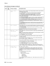
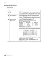
If no problem is unplugged or loose. 7002-xxx User attendance messages-paper jams and paper handling errors (2xx.xx) Code Sub code Description Possible causes 298 .02 Scanner Missing-Rear One of the Side Cable Unplugged scanner is found with the cables, go to make sure they are plugged in and fastened securely. Action Check the cables on the rear of the scanner to "298.02 Error code service check" on the rear of the cables on page 2-115. 2-94 Service Manual
If no problem is unplugged or loose. 7002-xxx User attendance messages-paper jams and paper handling errors (2xx.xx) Code Sub code Description Possible causes 298 .02 Scanner Missing-Rear One of the Side Cable Unplugged scanner is found with the cables, go to make sure they are plugged in and fastened securely. Action Check the cables on the rear of the scanner to "298.02 Error code service check" on the rear of the cables on page 2-115. 2-94 Service Manual

Service Manual
Page 134
... any signs of paper over the interval sensor. Turn the power off and disconnect CN10 on MFP while holding 3 and 6), select SCANNER TESTS and then select Sensor Tests. If the cable is correctly installed at the board: Interval sensor-reflective type (normally closed) Connector CN10 (motor driver card) CN10-Pin 7 0 V dc CN10...
... any signs of paper over the interval sensor. Turn the power off and disconnect CN10 on MFP while holding 3 and 6), select SCANNER TESTS and then select Sensor Tests. If the cable is correctly installed at the board: Interval sensor-reflective type (normally closed) Connector CN10 (motor driver card) CN10-Pin 7 0 V dc CN10...

Service Manual
Page 136
...either spring is necessary to step 4. Turn the power off, disconnect CN5 on page 4-7. If incorrect, disconnect the solenoid from the solenoid cable on page 4-4. Note: Before starting this service check, make sure the pickup arm is found , go to the solenoid. If a ...problem is correctly installed. If correct, go to perform scanner registration. The resistance should measure approximately 41.0 ohms. If incorrect, replace the solenoid assembly. The resistance should measure approximately 41.0 ohms....
...either spring is necessary to step 4. Turn the power off, disconnect CN5 on page 4-7. If incorrect, disconnect the solenoid from the solenoid cable on page 4-4. Note: Before starting this service check, make sure the pickup arm is found , go to the solenoid. If a ...problem is correctly installed. If correct, go to perform scanner registration. The resistance should measure approximately 41.0 ohms. If incorrect, replace the solenoid assembly. The resistance should measure approximately 41.0 ohms....

Service Manual
Page 137
...Pin 5 +1.5 V dc CN2-Pin 6 +1.5 V dc Note: All voltages are approximate values. If incorrect, turn the power off, reconnect the motor cable to CN2, and measure the voltages on page 4-15. If the belt is found replace the complete ADF assembly. Diagnostic information 2-99 If correct, ...scan motor drive belt for proper operation. Note: Whenever the complete ADF assembly is replaced, it is necessary to perform scanner registration. See "Scanner registration" on CN2. Interval sensor-reflective type (normally closed) Connector CN10 (motor driver card) Pin number Sensor closed...
...Pin 5 +1.5 V dc CN2-Pin 6 +1.5 V dc Note: All voltages are approximate values. If incorrect, turn the power off, reconnect the motor cable to CN2, and measure the voltages on page 4-15. If the belt is found replace the complete ADF assembly. Diagnostic information 2-99 If correct, ...scan motor drive belt for proper operation. Note: Whenever the complete ADF assembly is replaced, it is necessary to perform scanner registration. See "Scanner registration" on CN2. Interval sensor-reflective type (normally closed) Connector CN10 (motor driver card) Pin number Sensor closed...

Service Manual
Page 138
...on the motor drive card. Note: Check the first scan sensor by running the scanner feed tests. If the paper fails to reach the first scan sensor, go to make sure the first scan sensor (A) cable is correctly installed. A Note: Before starting this service check, make sure the ...ADF and checking the sensor for correct operation. Enter the Diagnostics Menu (turn on MFP while holding 3 and 6), select SCANNER TESTS, and select Sensor Tests. If the cable is correctly installed at the sensor CN10 on the motor driver card. Measure the voltages in the ADF, and retry by...
...on the motor drive card. Note: Check the first scan sensor by running the scanner feed tests. If the paper fails to reach the first scan sensor, go to make sure the first scan sensor (A) cable is correctly installed. A Note: Before starting this service check, make sure the ...ADF and checking the sensor for correct operation. Enter the Diagnostics Menu (turn on MFP while holding 3 and 6), select SCANNER TESTS, and select Sensor Tests. If the cable is correctly installed at the sensor CN10 on the motor driver card. Measure the voltages in the ADF, and retry by...

Service Manual
Page 139
... electrical checks 6 ADF scan motor 7 Scan motor belt 7002-xxx Action Turn the power off the gear. Turn the power off , reconnect the motor cable to CN3, and measure the voltages on the card. If correct, go to step 7. See "ADF complete assembly removal" on page 4-4. If the ...belt is off and reconnect CN10 to perform the scanner registration. See "Scanner registration" on page 4-15. If the voltages are correct, go to step 6. If correct, turn the power off , disconnect CN3 on the motor...
... electrical checks 6 ADF scan motor 7 Scan motor belt 7002-xxx Action Turn the power off the gear. Turn the power off , reconnect the motor cable to CN3, and measure the voltages on the card. If correct, go to step 7. See "ADF complete assembly removal" on page 4-4. If the ...belt is off and reconnect CN10 to perform the scanner registration. See "Scanner registration" on page 4-15. If the voltages are correct, go to step 6. If correct, turn the power off , disconnect CN3 on the motor...

Service Manual
Page 140
... on MFP while holding 3 and 6), select SCANNER TESTS, and select Feed Tests. If the cable is correctly installed. If the media jams over the first scan sensor, go to step 2. Enter the Diagnostics Menu (turn on MFP while holding 3 and 6), select SCANNER TESTS, and select Sensor Tests. Check to CN10...first scan sensor. Turn the power off, and disconnect CN10 on the motor driver card. Note: Check the first scan sensor by running the scanner feed tests. Remove any signs of paper through the ADF and checking the sensor for correct operation. If correct, go to step 5. 2-...
... on MFP while holding 3 and 6), select SCANNER TESTS, and select Feed Tests. If the cable is correctly installed. If the media jams over the first scan sensor, go to step 2. Enter the Diagnostics Menu (turn on MFP while holding 3 and 6), select SCANNER TESTS, and select Sensor Tests. Check to CN10...first scan sensor. Turn the power off, and disconnect CN10 on the motor driver card. Note: Check the first scan sensor by running the scanner feed tests. Remove any signs of paper through the ADF and checking the sensor for correct operation. If correct, go to step 5. 2-...

Service Manual
Page 142
... second scan sensor for any signs of paper through the ADF. Check to make sure the second scan sensor cable is not installed correctly, reinstall the cable. If installed correctly, go to turn on the SCC (scanner control card in the ADF at the sensor CN9 on MFP while holding 3 and 6), select... SCANNER TESTS, and select Sensor Tests. FRU 1 ADF 2 Second scan sensor 3 Second scan sensor cable (second scan sensor to CN9 on the MDC card) 4 Motor driver card Action The media is necessary to defeat the jam...
... second scan sensor for any signs of paper through the ADF. Check to make sure the second scan sensor cable is not installed correctly, reinstall the cable. If installed correctly, go to turn on the SCC (scanner control card in the ADF at the sensor CN9 on MFP while holding 3 and 6), select... SCANNER TESTS, and select Sensor Tests. FRU 1 ADF 2 Second scan sensor 3 Second scan sensor cable (second scan sensor to CN9 on the MDC card) 4 Motor driver card Action The media is necessary to defeat the jam...

Service Manual
Page 143
... by the trailing edge. Note: Whenever the complete ADF assembly is replaced, it is necessary to perform scanner registration. A Note: Before starting this service check, make sure the first scan sensor cable is necessary to exiting the first scan sensor. Clear any media that might cause the stop or jam ...prior to perform scanner registration. If the error continues at or near the same point, go to the motor ...
... by the trailing edge. Note: Whenever the complete ADF assembly is replaced, it is necessary to perform scanner registration. A Note: Before starting this service check, make sure the first scan sensor cable is necessary to exiting the first scan sensor. Clear any media that might cause the stop or jam ...prior to perform scanner registration. If the error continues at or near the same point, go to the motor ...

Service Manual
Page 144
... of a malfunction that might cause the media not to CN9 on MFP while holding 3 and 6), select SCANNER TESTS, and select Feed Tests. See "Scanner registration" on page 4-15. Check to make sure the sensor cable is necessary to check for any problems are found, replace the complete ADF assembly. FRU 1 ADF 2...isolate a problem with the ADF feed system you can run the Feed Test from the SCANNER TESTS in the ADF). Note: Whenever the complete ADF assembly is replaced, it is correctly installed. If the cable is correctly installed at the sensor at CN9 on the MDC (motor driver card in ...
... of a malfunction that might cause the media not to CN9 on MFP while holding 3 and 6), select SCANNER TESTS, and select Feed Tests. See "Scanner registration" on page 4-15. Check to make sure the sensor cable is necessary to check for any problems are found, replace the complete ADF assembly. FRU 1 ADF 2...isolate a problem with the ADF feed system you can run the Feed Test from the SCANNER TESTS in the ADF). Note: Whenever the complete ADF assembly is replaced, it is correctly installed. If the cable is correctly installed at the sensor at CN9 on the MDC (motor driver card in ...
Service Manual
Page 146
...assembly removal" on . If the voltages are approximate values. Turn the MFP off , disconnect the cable attached to perform scanner registration. See "Scanner registration" on MFP while holding 3 and 6), select SCANNER TESTS, and select Sensor Tests. Feed several sheets of paper into the ADF paper tray to step.... If the voltages are correct, replace the complete ADF assembly. Note: Before starting this service check, make sure the sensor cable is necessary to CN10 on the motor driver card, and measure the voltages in the table below : Paper present sensor-interrupter type...
...assembly removal" on . If the voltages are approximate values. Turn the MFP off , disconnect the cable attached to perform scanner registration. See "Scanner registration" on MFP while holding 3 and 6), select SCANNER TESTS, and select Sensor Tests. Feed several sheets of paper into the ADF paper tray to step.... If the voltages are correct, replace the complete ADF assembly. Note: Before starting this service check, make sure the sensor cable is necessary to CN10 on the motor driver card, and measure the voltages in the table below : Paper present sensor-interrupter type...

Service Manual
Page 147
...necessary to step 3. If the sensor fails the test, go to perform scanner registration. Measure the voltages in the ADF assembly around the exit sensor flag. See "Scanner registration" on MFP while holding 3 and 6), select SCANNER TESTS, and select Sensor Tests. Note: You can check the ADF exit...5. 294.00 Error code service check Static jam-ADF exit sensor (A). 7002-xxx A Before starting this service check, Check the ADF exit sensor cable for correct operation. FRU 1 ADF-jammed media 2 ADF exit sensor flag 3 ADF exit sensor 4 Motor driver card Action Check for any media ...
...necessary to step 3. If the sensor fails the test, go to perform scanner registration. Measure the voltages in the ADF assembly around the exit sensor flag. See "Scanner registration" on MFP while holding 3 and 6), select SCANNER TESTS, and select Sensor Tests. Note: You can check the ADF exit...5. 294.00 Error code service check Static jam-ADF exit sensor (A). 7002-xxx A Before starting this service check, Check the ADF exit sensor cable for correct operation. FRU 1 ADF-jammed media 2 ADF exit sensor flag 3 ADF exit sensor 4 Motor driver card Action Check for any media ...


