
User's Guide
Page 129
... 129 Replacement of the maintenance kit. See Recycling Lexmark products for more frequent replacement of the fuser must be individually ordered and replaced as necessary. For information about maintenance kits available for your specific MFP. Ordering a maintenance kit 80 Scheduled maintenance advised appears on the ... to ship the old cartridge back to replace the pick rollers, the charge roll, transfer roller, and the fuser. Maintenance kit for X642e Part numbers 40X0102 (100 V) 40X0100 (110 V) 40X0101 (220 V) For information about the print cartridges available for the...
... 129 Replacement of the maintenance kit. See Recycling Lexmark products for more frequent replacement of the fuser must be individually ordered and replaced as necessary. For information about maintenance kits available for your specific MFP. Ordering a maintenance kit 80 Scheduled maintenance advised appears on the ... to ship the old cartridge back to replace the pick rollers, the charge roll, transfer roller, and the fuser. Maintenance kit for X642e Part numbers 40X0102 (100 V) 40X0100 (110 V) 40X0101 (220 V) For information about the print cartridges available for the...

User's Guide
Page 191
... 140 SNMPv1, disabling 141 SNMPv2, disabling 141 Start button 16 static sensitivity notice 3 status message bar 18 Stop button 16 supplies label fuser cleaner 130 maintenance kit 129 print cartridge 127 recycling 131 T time stamp 31 toner cartridge recycling 131 transfer roller 130 transparencies loading input tray 79 transparencies, copying 32 tray...
... 140 SNMPv1, disabling 141 SNMPv2, disabling 141 Start button 16 static sensitivity notice 3 status message bar 18 Stop button 16 supplies label fuser cleaner 130 maintenance kit 129 print cartridge 127 recycling 131 T time stamp 31 toner cartridge recycling 131 transfer roller 130 transparencies loading input tray 79 transparencies, copying 32 tray...
Service Manual
Page 9
... 5-17 Motor driver board 5-23 Flatbed interconnect card 5-26 Modem card 5-31 Preventive maintenance 6-1 Safety inspection guide 6-1 Lubrication specifications 6-1 Scheduled maintenance 6-1 Maintenance kit 6-1 Cleaning the scanner glass, cushions, and strips 6-2 Parts catalog 7-1 How to use this parts catalog 7-1 Assembly 1: Covers-printer (model X642e 7-2 Assembly 2: Cover-printer (models X644e and X646e 7-6 Assembly 3: Covers-ADF scanner 7-8 Assembly...
... 5-17 Motor driver board 5-23 Flatbed interconnect card 5-26 Modem card 5-31 Preventive maintenance 6-1 Safety inspection guide 6-1 Lubrication specifications 6-1 Scheduled maintenance 6-1 Maintenance kit 6-1 Cleaning the scanner glass, cushions, and strips 6-2 Parts catalog 7-1 How to use this parts catalog 7-1 Assembly 1: Covers-printer (model X642e 7-2 Assembly 2: Cover-printer (models X644e and X646e 7-6 Assembly 3: Covers-ADF scanner 7-8 Assembly...

Service Manual
Page 210
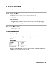
... at J15-3. Check the right transfer arm assembly spring for toner buildup, surface damage to make sure the arm is replaced when an 80 Scheduled Maintenance displays. The voltage changes from +24 V dc with the printer idle to the HVPS. FRU 1 Transfer roll assembly 2 Left transfer arm assembly 3 Right ... and to prevent damage to "Print quality-background" on the surface of the roll. If the voltage is incorrect, check the continuity of the maintenance kit and is not broken and locks into the EP frame correctly. If the arm is not locked down, make sure it is fastened and locked...
... at J15-3. Check the right transfer arm assembly spring for toner buildup, surface damage to make sure the arm is replaced when an 80 Scheduled Maintenance displays. The voltage changes from +24 V dc with the printer idle to the HVPS. FRU 1 Transfer roll assembly 2 Left transfer arm assembly 3 Right ... and to prevent damage to "Print quality-background" on the surface of the roll. If the voltage is incorrect, check the continuity of the maintenance kit and is not broken and locks into the EP frame correctly. If the arm is not locked down, make sure it is fastened and locked...
Service Manual
Page 235
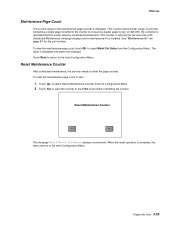
...At 300,000, the customer is installed. See "Maintenance kit" on page 6-1 for the maintenance page counter is displayed. The Touch Back to return to reset the page counter. Reset Maintenance Counter After scheduled maintenance, the servicer needs to the main Configuration Menu. ...single page increments the counter by one and a duplex page by the servicer after a 80 Scheduled Maintenance message displays and a maintenance kit is reminded that the printer requires scheduled maintenance. to the main Configuration Menu. Diagnostic aids 3-25 Touch Yes to reset the counter or touch ...
...At 300,000, the customer is installed. See "Maintenance kit" on page 6-1 for the maintenance page counter is displayed. The Touch Back to return to reset the page counter. Reset Maintenance Counter After scheduled maintenance, the servicer needs to the main Configuration Menu. ...single page increments the counter by one and a duplex page by the servicer after a 80 Scheduled Maintenance message displays and a maintenance kit is reminded that the printer requires scheduled maintenance. to the main Configuration Menu. Diagnostic aids 3-25 Touch Yes to reset the counter or touch ...
Service Manual
Page 433
..., missing, or altered parts, especially in the area of the on page 3-25. If any non-Lexmark attachments. Check the following part numbers: Maintenance kits Description 115 V Maintenance kit 220 V Maintenance kit 100 V Maintenance kit Part number 40X0100 40X0101 40X0197 After replacing the kit, the maintenance count must be and if you can help prevent problems and maintain optimum performance. Preventive...
..., missing, or altered parts, especially in the area of the on page 3-25. If any non-Lexmark attachments. Check the following part numbers: Maintenance kits Description 115 V Maintenance kit 220 V Maintenance kit 100 V Maintenance kit Part number 40X0100 40X0101 40X0197 After replacing the kit, the maintenance count must be and if you can help prevent problems and maintain optimum performance. Preventive...
Service Manual
Page 509
...tray 7-30 500-sheet paper tray, option parts catalog 7-62 service check 2-147 80 scheduled maintenance 6-1 8xx Service error codes 2-13 900.xx error code service check 2-118 950.00 through... 7-15 Button Test 3-8 buttons accessing service menus 3-1 Button Test 3-8 upper front cover including buttons 7-7 upper front panel button kit 7-7 C cable diagrams 7-43, 7-44, 7-45, 7-46, 7-48, 7-50 cabling diagrams 7-52, 7-56, 7-57...31 motor driver board 5-23 operator panel card (UICC #1)-model X642e 5-12 operator panel card (UICC #1)-models X644e/X646e 5-14 scanner control card 5-17 system board 5-3 USB card ...
...tray 7-30 500-sheet paper tray, option parts catalog 7-62 service check 2-147 80 scheduled maintenance 6-1 8xx Service error codes 2-13 900.xx error code service check 2-118 950.00 through... 7-15 Button Test 3-8 buttons accessing service menus 3-1 Button Test 3-8 upper front cover including buttons 7-7 upper front panel button kit 7-7 C cable diagrams 7-43, 7-44, 7-45, 7-46, 7-48, 7-50 cabling diagrams 7-52, 7-56, 7-57...31 motor driver board 5-23 operator panel card (UICC #1)-model X642e 5-12 operator panel card (UICC #1)-models X644e/X646e 5-14 scanner control card 5-17 system board 5-3 USB card ...

Service Manual
Page 512
... left cover handle holder removal 4-72 LES Applications 3-34 Lexmark Embedded Solution 3-34 locations ADF sensors 5-2 flatbed sensors ... check 2-153 main fan removal 4-111 maintenance ESD-sensitive parts 4-1 flatbed white cushion 6-2 lubrication 6-1 maintenance kit 6-1 preventive 6-1 safety inspection guide 6-1 scanner glass 6-2 maintenance approach 1-1 maintenance kits 6-1 media specifications 1-9 Menu button, service... Test 3-8 description 2-2 LCD inverter board 5-16 operator panel card (UICC #1), model X642e 5-12 operator panel card, models X644e/X646e 5-14 Panel Test 3-8 right cover assembly...
... left cover handle holder removal 4-72 LES Applications 3-34 Lexmark Embedded Solution 3-34 locations ADF sensors 5-2 flatbed sensors ... check 2-153 main fan removal 4-111 maintenance ESD-sensitive parts 4-1 flatbed white cushion 6-2 lubrication 6-1 maintenance kit 6-1 preventive 6-1 safety inspection guide 6-1 scanner glass 6-2 maintenance approach 1-1 maintenance kits 6-1 media specifications 1-9 Menu button, service... Test 3-8 description 2-2 LCD inverter board 5-16 operator panel card (UICC #1), model X642e 5-12 operator panel card, models X644e/X646e 5-14 Panel Test 3-8 right cover assembly...
Service Manual
Page 513
..., 7-50, 7-52, 7-56, 7-57 covers-ADF scanner 7-8 covers-printer 7-2 covers-printer-model X642e 7-2 covers-printer-model X644e/X646e 7-6 drives-main drive and developer drive 7-32 duplex option 7-63 ... 4-105 MPF 4-118 power takeoff shaft and spring 4-126 PPDS Emulation 3-27 preventive maintenance 6-1 print quality pages 3-7, 3-26 print registration 3-5 7002-xxx printhead adjustment 4-2 parts... Scanner Manual Registration 4-5 relocation kit 7-71 removal procedures and cautions 4-6 removals printer removals bevel gear 4-75 developer drive assembly 4-77 developer drive coupler kit 4-78 ESD cover 4-78...
..., 7-50, 7-52, 7-56, 7-57 covers-ADF scanner 7-8 covers-printer 7-2 covers-printer-model X642e 7-2 covers-printer-model X644e/X646e 7-6 drives-main drive and developer drive 7-32 duplex option 7-63 ... 4-105 MPF 4-118 power takeoff shaft and spring 4-126 PPDS Emulation 3-27 preventive maintenance 6-1 print quality pages 3-7, 3-26 print registration 3-5 7002-xxx printhead adjustment 4-2 parts... Scanner Manual Registration 4-5 relocation kit 7-71 removal procedures and cautions 4-6 removals printer removals bevel gear 4-75 developer drive assembly 4-77 developer drive coupler kit 4-78 ESD cover 4-78...
Service Manual
Page 517
... feed alignment assembly paper feed 7-29 Reference ground clip 7-29 Parts packet (reference adjust 7-29 Tray assembly-500-sheet tray 7-31 Side restraint 7-31 115 V Maintenance kit 6-1 220 V Maintenance kit 6-1 Pass thru plate-500-sheet tray 7-31 Restraint pad 7-31 Part number index I-9
... feed alignment assembly paper feed 7-29 Reference ground clip 7-29 Parts packet (reference adjust 7-29 Tray assembly-500-sheet tray 7-31 Side restraint 7-31 115 V Maintenance kit 6-1 220 V Maintenance kit 6-1 Pass thru plate-500-sheet tray 7-31 Restraint pad 7-31 Part number index I-9
Service Manual
Page 518
... Fuser lamp, 115V 7-35 Fuser lamp, 220V 7-35 Narrow media sensor 7-35 Exit sensor 7-35 Parts kit, charge roll link asm, left side 7-37 Charge roll assembly 7-37 Parts kit, right side charge roll link assembly 7-37 Transfer roll assembly 7-37 Transfer roll assembly right arm 7-37 ...package, empty 7-71 Parts packet (cable ties 7-5, 7-7 Nyogel 744 grease packet 7-71 Wear strip 7-31 Plate, 500-sheet tray wear 7-31 100 V Maintenance kit 6-1 EP duct 7-15 Blower duct 7-15 Gear #60 MPF shield 7-15 Tray bias assembly 7-15 Paper low/out sensor card assembly 7-25 HVPS/input sensor...
... Fuser lamp, 115V 7-35 Fuser lamp, 220V 7-35 Narrow media sensor 7-35 Exit sensor 7-35 Parts kit, charge roll link asm, left side 7-37 Charge roll assembly 7-37 Parts kit, right side charge roll link assembly 7-37 Transfer roll assembly 7-37 Transfer roll assembly right arm 7-37 ...package, empty 7-71 Parts packet (cable ties 7-5, 7-7 Nyogel 744 grease packet 7-71 Wear strip 7-31 Plate, 500-sheet tray wear 7-31 100 V Maintenance kit 6-1 EP duct 7-15 Blower duct 7-15 Gear #60 MPF shield 7-15 Tray bias assembly 7-15 Paper low/out sensor card assembly 7-25 HVPS/input sensor...


