Service Manual
Page 24
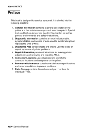
Repair Information provides instructions for individual FRUs. General Information contains a general description of printer problems. 4. Special tools and test equipment are listed in this chapter, as ... part numbers for making printer adjustments and removing and installing FRUs. 5. 4069-5XX/7XX Preface This book is divided into the following chapters: 1. xxiv Service Manual Connector Locations uses illustrations to repair it. It is designed for service personnel.
Repair Information provides instructions for individual FRUs. General Information contains a general description of printer problems. 4. Special tools and test equipment are listed in this chapter, as ... part numbers for making printer adjustments and removing and installing FRUs. 5. 4069-5XX/7XX Preface This book is divided into the following chapters: 1. xxiv Service Manual Connector Locations uses illustrations to repair it. It is designed for service personnel.
Service Manual
Page 27
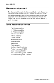
...FRU) or part. Use the service error codes, user status messages, user error messages, service checks, and diagnostic aids to determine the printer problem and repair the failure. Tools Required for Service Flat-blade screwdriver #1 Phillips screwdriver #2 Phillips screwdriver T10 Torx screwdriver 7.0 mm nut driver 5.5 mm wrench Needlenose pliers ... 1329048 Twinax/serial debug cable 1381963 Coax/serial debug cable 1381964 General Information 1-3 4069-5XX/7XX Maintenance Approach The diagnostic information in this manual leads you complete the repair, perform tests as needed to verify the...
...FRU) or part. Use the service error codes, user status messages, user error messages, service checks, and diagnostic aids to determine the printer problem and repair the failure. Tools Required for Service Flat-blade screwdriver #1 Phillips screwdriver #2 Phillips screwdriver T10 Torx screwdriver 7.0 mm nut driver 5.5 mm wrench Needlenose pliers ... 1329048 Twinax/serial debug cable 1381963 Coax/serial debug cable 1381964 General Information 1-3 4069-5XX/7XX Maintenance Approach The diagnostic information in this manual leads you complete the repair, perform tests as needed to verify the...

Service Manual
Page 88
...Latch Assembly 4 Master Cam Gear Master/ Kick Gear Action Check the belt for correct installation and for signs of loose wires or poor connections. Repair or replace parts as necessary. If not, then the tenons on J4-1. If incorrect, replace the envelope feeder system board. motor assembly. ...incorrect, replace the envelope system board, if correct, measure the voltage at J4-6. If incorrect, replace the master kick gear. 2-60 Service Manual Check the master cam gear and master/kick gear to make sure they rotate together. 4069-5XX/7XX 990 Service Error, envelopes fail to...
...Latch Assembly 4 Master Cam Gear Master/ Kick Gear Action Check the belt for correct installation and for signs of loose wires or poor connections. Repair or replace parts as necessary. If not, then the tenons on J4-1. If incorrect, replace the envelope feeder system board. motor assembly. ...incorrect, replace the envelope system board, if correct, measure the voltage at J4-6. If incorrect, replace the master kick gear. 2-60 Service Manual Check the master cam gear and master/kick gear to make sure they rotate together. 4069-5XX/7XX 990 Service Error, envelopes fail to...

Service Manual
Page 98
... shaft bearings. Check the drive roll assembly and skewed backup roller for signs of X for the paper tray where the error occurs. Repair or replace parts as necessary. 2-70 Service Manual If incorrect, replace the tray x option pass thru sensor assembly. Also check for signs of the paper aligning assembly. Check these...
... shaft bearings. Check the drive roll assembly and skewed backup roller for signs of X for the paper tray where the error occurs. Repair or replace parts as necessary. 2-70 Service Manual If incorrect, replace the tray x option pass thru sensor assembly. Also check for signs of the paper aligning assembly. Check these...

Service Manual
Page 102
... sure it is mounted correctly and is incorrect, check the continuity of the LVPS. 2-74 Service Manual If incorrect, replace the AC cable to the input of the AC input cable to the LVPS. Repair the high capacity option autoconnect as necessary. If the voltage is not pushed down into the frame...
... sure it is mounted correctly and is incorrect, check the continuity of the LVPS. 2-74 Service Manual If incorrect, replace the AC cable to the input of the AC input cable to the LVPS. Repair the high capacity option autoconnect as necessary. If the voltage is not pushed down into the frame...

Service Manual
Page 104
... not detect a piece of X for proper operation. Check these parts for signs of broken or damaged parts, contamination on the rollers. Repair or replace parts as necessary. 2-76 Service Manual Check the drive roll assembly and skewed backup roller for signs of wear, slick spots, material buildup, and oil or grease on...
... not detect a piece of X for proper operation. Check these parts for signs of broken or damaged parts, contamination on the rollers. Repair or replace parts as necessary. 2-76 Service Manual Check the drive roll assembly and skewed backup roller for signs of wear, slick spots, material buildup, and oil or grease on...
Service Manual
Page 122
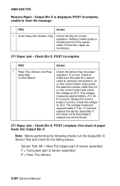
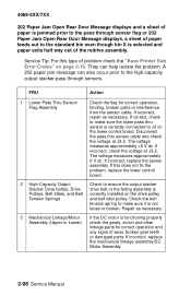
... Flag Assembly Control Board Action Check the sensor flag for the failing sensor. Disconnect the pass thru sensor cable from the sensor cable, If incorrect, repair as necessary. 271 Paper Jam - 4069-5XX/7XX Remove Paper - If correct, check to make sure the pass thru sensor cable is displayed, POST incomplete... J3 on the control board and check the voltage at J3-2. Check Bin X, POST complete, first sheet of sensor assembly) P = Pass Thru Sensor 2-94 Service Manual The voltage measures approximately +5 V dc. If incorrect, replace the sensor assembly.
... Flag Assembly Control Board Action Check the sensor flag for the failing sensor. Disconnect the pass thru sensor cable from the sensor cable, If incorrect, repair as necessary. 271 Paper Jam - 4069-5XX/7XX Remove Paper - If correct, check to make sure the pass thru sensor cable is displayed, POST incomplete... J3 on the control board and check the voltage at J3-2. Check Bin X, POST complete, first sheet of sensor assembly) P = Pass Thru Sensor 2-94 Service Manual The voltage measures approximately +5 V dc. If incorrect, replace the sensor assembly.
Service Manual
Page 126
...problem, replace the lower control board. 2 High-Capacity Output Check to J3 on the lower control board. If incorrect, repair as necessary. 3 Mechanical Linkage/Motor Assembly (Upper or Lower) If the DC motor is correctly connected to ensure the output... bin even though bin X is not loose or broken. A 202 paper jam message can help isolate the problem. Repair as necessary. Disconnect the pass thru sensor cable and check the voltage at J3-2. If incorrect, replace the sensor assembly... pulley. If incorrect, replace the mechanical linkage assembly/DC Motor Assembly. 2-98 Service Manual
...problem, replace the lower control board. 2 High-Capacity Output Check to J3 on the lower control board. If incorrect, repair as necessary. 3 Mechanical Linkage/Motor Assembly (Upper or Lower) If the DC motor is correctly connected to ensure the output... bin even though bin X is not loose or broken. A 202 paper jam message can help isolate the problem. Repair as necessary. Disconnect the pass thru sensor cable and check the voltage at J3-2. If incorrect, replace the sensor assembly... pulley. If incorrect, replace the mechanical linkage assembly/DC Motor Assembly. 2-98 Service Manual

Service Manual
Page 146
Repair or replace as necessary. If there is mounted correctly and securely grounded. The resistance measures approximately 0 ohms. If incorrect, make sure the system board is ... the voltage does not vary, check the continuity of toner buildup or other contamination on the page. If correct, replace the system board. 2-118 Service Manual If this does not correct the problem, replace the system board. If there is no continuity, replace the cable harness. 4069-5XX/7XX FRU 2 Charge...
Repair or replace as necessary. If there is mounted correctly and securely grounded. The resistance measures approximately 0 ohms. If incorrect, make sure the system board is ... the voltage does not vary, check the continuity of toner buildup or other contamination on the page. If correct, replace the system board. 2-118 Service Manual If this does not correct the problem, replace the system board. If there is no continuity, replace the cable harness. 4069-5XX/7XX FRU 2 Charge...

Service Manual
Page 148
... roll for any noticeable buildup of toner. Toner on the backside of the media. Repair as necessary. This problem is generally caused by loose toner in the machine in the following order: HVPS system board 2-120 Service Manual Check the transfer roll for any signs of toner buildup or loose toner around...
... roll for any noticeable buildup of toner. Toner on the backside of the media. Repair as necessary. This problem is generally caused by loose toner in the machine in the following order: HVPS system board 2-120 Service Manual Check the transfer roll for any signs of toner buildup or loose toner around...

