Service Manual
Page 43
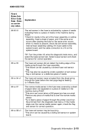
...select the base sensor test. Note: xx can be caused by a piece of media indicating there is present, check the exit sensor assembly, internal fuser assembly cabling, DC fuser cable to the system board, and the cable connection to feed a piece of paper through the printer (could run the print test ... operation of exit sensor flag or exit sensor or a defective piece of the fuser assembly or redrive assembly. Explanation 89 00 01 The exit sensor in the exit of media. 89 xx 04 x1 The fuser exit sensor never actuated from the diagnostic test menu). Select output sensor and check...
...select the base sensor test. Note: xx can be caused by a piece of media indicating there is present, check the exit sensor assembly, internal fuser assembly cabling, DC fuser cable to the system board, and the cable connection to feed a piece of paper through the printer (could run the print test ... operation of exit sensor flag or exit sensor or a defective piece of the fuser assembly or redrive assembly. Explanation 89 00 01 The exit sensor in the exit of media. 89 xx 04 x1 The fuser exit sensor never actuated from the diagnostic test menu). Select output sensor and check...

Service Manual
Page 45
...from a paper source interfered with the next pick x2 retry. (x-1=Media Size)(x-2=Media Source) Base Printer (Fuser) Sub Error Codes The following Sub Error Codes could be any value. Fuser Error (Fuser under temperature while at standby) Diagnostic Information 2-17 Note: xx can be any value Explanation 920 Service -... of media. 8E xx 11 It took too long to heat up to come up . Fuser Error (Under temperature while printing) EN 08 xx yy - 1 EN- Note: xx can be a help in diagnosing Fuser Assembly failures: First 6 Bytes Sub Error Code Data - zz=01 The Hot Roll fell too ...
...from a paper source interfered with the next pick x2 retry. (x-1=Media Size)(x-2=Media Source) Base Printer (Fuser) Sub Error Codes The following Sub Error Codes could be any value. Fuser Error (Fuser under temperature while at standby) Diagnostic Information 2-17 Note: xx can be any value Explanation 920 Service -... of media. 8E xx 11 It took too long to heat up to come up . Fuser Error (Under temperature while printing) EN 08 xx yy - 1 EN- Note: xx can be a help in diagnosing Fuser Assembly failures: First 6 Bytes Sub Error Code Data - zz=01 The Hot Roll fell too ...
Service Manual
Page 64
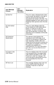
... reliability of the printer. Disk operations are available as bad and normal operation continues. For more information, go to clear this interval to replace the fuser assembly, transfer roller, and charge roll at each 300K page count interval. The parts are not allowed until the disk is formatted. 4069-5XX/7XX User...
... reliability of the printer. Disk operations are available as bad and normal operation continues. For more information, go to clear this interval to replace the fuser assembly, transfer roller, and charge roll at each 300K page count interval. The parts are not allowed until the disk is formatted. 4069-5XX/7XX User...
Service Manual
Page 93
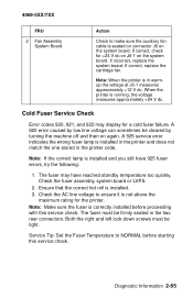
... be tight. 4069-5XX/7XX FRU 2 Fan Assembly System Board Action Check to make sure the auxiliary fan cable is installed. 3. Cold Fuser Service Check Error codes 920, 921, and 922 may have 925 fuser errors, try the following: 1. Ensure that the correct hot roll is seated on connector J6 on the system... in the two rear connectors. Check the AC line voltage to NORMAL before proceeding with this service check. Check the fuser assembly, system board or LVPS. 2. Both the right and left lock down screws must be cleared by turning the machine off and then on the system ...
... be tight. 4069-5XX/7XX FRU 2 Fan Assembly System Board Action Check to make sure the auxiliary fan cable is installed. 3. Cold Fuser Service Check Error codes 920, 921, and 922 may have 925 fuser errors, try the following: 1. Ensure that the correct hot roll is seated on connector J6 on the system... in the two rear connectors. Check the AC line voltage to NORMAL before proceeding with this service check. Check the fuser assembly, system board or LVPS. 2. Both the right and left lock down screws must be cleared by turning the machine off and then on the system ...

Service Manual
Page 94
..., turn the printer off . Disconnect the thermistor cable. Check the fuser assembly, system board or LVPS. 2. Check the AC line voltage to Fuser Auto Docking Connector Fuser AC Cable 4 Fuser Top Cover Assembly (Thermal Fuse/Thermistor Assembly) Action Install the correct voltage and wattage lamp or fuser assembly. Check the continuity of the lamp. The resistance is installed. 3. The...
..., turn the printer off . Disconnect the thermistor cable. Check the fuser assembly, system board or LVPS. 2. Check the AC line voltage to Fuser Auto Docking Connector Fuser AC Cable 4 Fuser Top Cover Assembly (Thermal Fuse/Thermistor Assembly) Action Install the correct voltage and wattage lamp or fuser assembly. Check the continuity of the lamp. The resistance is installed. 3. The...

Service Manual
Page 95
...on J14-6 on the system board. Examine the fuser assembly for damage to the thermistor assembly. Diagnostic Information 2-67 CAUTION: The fuser may display for a hot fuser failure. FRU 1 Fuser Cover Assembly (Assembly includes Thermistor and Thermal Fuses.) 2 System Board 3 Fuser Hot Roll Backup Roll Bearings Action Check for signs... of overheating or damage. Error code 924 indicates the system board detects an open circuit in the fuser assembly and the DC fuser cable (system board to auto docking connector) attached to 260K ohms If the resistance is no continuity, replace...
...on J14-6 on the system board. Examine the fuser assembly for damage to the thermistor assembly. Diagnostic Information 2-67 CAUTION: The fuser may display for a hot fuser failure. FRU 1 Fuser Cover Assembly (Assembly includes Thermistor and Thermal Fuses.) 2 System Board 3 Fuser Hot Roll Backup Roll Bearings Action Check for signs... of overheating or damage. Error code 924 indicates the system board detects an open circuit in the fuser assembly and the DC fuser cable (system board to auto docking connector) attached to 260K ohms If the resistance is no continuity, replace...

Service Manual
Page 96
... Adjustment" on . The resistance measures between J4 on the system board and the DC autocount on the fuser assembly. 4069-5XX/7XX Fuser Solenoid Service Check Service Tip: Try changing the envelope enhance level setting. If the cable measures continuity, replace the ... replace the cable. If incorrect, replace the cable. 2 Fuser DC Cable (System Board to closed as described in and out of the solenoid Cable inside Fuser Assembly and associated hardware, link and so on page 4-3. FRU Action 1 Fuser Envelope Conditioner The operation of the solenoid. A different setting ...
... Adjustment" on . The resistance measures between J4 on the system board and the DC autocount on the fuser assembly. 4069-5XX/7XX Fuser Solenoid Service Check Service Tip: Try changing the envelope enhance level setting. If the cable measures continuity, replace the ... replace the cable. If incorrect, replace the cable. 2 Fuser DC Cable (System Board to closed as described in and out of the solenoid Cable inside Fuser Assembly and associated hardware, link and so on page 4-3. FRU Action 1 Fuser Envelope Conditioner The operation of the solenoid. A different setting ...
Service Manual
Page 137
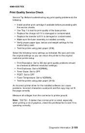
...printhead fan to printer ground. Measure all voltages from the connector to see if it is damaged or contaminated. • Make sure the fuser assembly is installed correctly. • Verify proper paper type, texture and weight settings for the installed software can return the printer to the original... different resolution settings). • Print Darkness: Set to NORMAL. • Toner Saver: Set to OFF. • PQET: Set to OFF. • Fuser Temperature: Set to NORMAL. • Test the printer using plain paper (20 lb) An incorrect printer driver for the media being used. • Test...
...printhead fan to printer ground. Measure all voltages from the connector to see if it is damaged or contaminated. • Make sure the fuser assembly is installed correctly. • Verify proper paper type, texture and weight settings for the installed software can return the printer to the original... different resolution settings). • Print Darkness: Set to NORMAL. • Toner Saver: Set to OFF. • PQET: Set to OFF. • Fuser Temperature: Set to NORMAL. • Test the printer using plain paper (20 lb) An incorrect printer driver for the media being used. • Test...

Service Manual
Page 142
...background problems can be caused by increasing the transfer setting. Replace the redrive assembly. Replace the FRUs in the following order: alignment assembly main drive gearbox assembly Replace the FRUs in the following order: redrive assembly fuser assembly Replace the transfer roll. Some slick or coated papers may try to ...that run a large amount of life. 2-114 Service Manual Replace the alignment assembly. Check the charge roll to make sure it is set to improve the print quality by rough papers, non-Lexmark toner cartridges or if the media texture is not at the end of ...
...background problems can be caused by increasing the transfer setting. Replace the redrive assembly. Replace the FRUs in the following order: alignment assembly main drive gearbox assembly Replace the FRUs in the following order: redrive assembly fuser assembly Replace the transfer roll. Some slick or coated papers may try to ...that run a large amount of life. 2-114 Service Manual Replace the alignment assembly. Check the charge roll to make sure it is set to improve the print quality by rough papers, non-Lexmark toner cartridges or if the media texture is not at the end of ...

Service Manual
Page 147
...or contamination. Diagnostic Information 2-119 4069-5XX/7XX Print Quality - Print Quality - FRU 1 Transfer Roll 2 Right Side Transfer Roll Arm Assembly Action Check the right end of the transfer roll shaft for any signs of the cable from the bearing to the bearing. Also check... on the cable. If incorrect, replace the right side transfer arm assembly. If incorrect, replace the right side transfer arm assembly. FRU 1 Hot Roll Fuser Assembly Action Check the fuser assembly for signs of the transfer roll assembly cable to be caused by the photoconductor, cleaning blade and other parts...
...or contamination. Diagnostic Information 2-119 4069-5XX/7XX Print Quality - Print Quality - FRU 1 Transfer Roll 2 Right Side Transfer Roll Arm Assembly Action Check the right end of the transfer roll shaft for any signs of the cable from the bearing to the bearing. Also check... on the cable. If incorrect, replace the right side transfer arm assembly. If incorrect, replace the right side transfer arm assembly. FRU 1 Hot Roll Fuser Assembly Action Check the fuser assembly for signs of the transfer roll assembly cable to be caused by the photoconductor, cleaning blade and other parts...

Service Manual
Page 148
... on the backside of the media. This problem is generally caused by a toner buildup on the backside of the paper. FRU 1 Hot Roll Fuser Assembly 2 Transfer Roll Transfer Plate Assembly Action Toner is being carried through the printer on backside of printed page Service Tip: This is generally caused by loose toner in...
... on the backside of the media. This problem is generally caused by a toner buildup on the backside of the paper. FRU 1 Hot Roll Fuser Assembly 2 Transfer Roll Transfer Plate Assembly Action Toner is being carried through the printer on backside of printed page Service Tip: This is generally caused by loose toner in...
Service Manual
Page 205
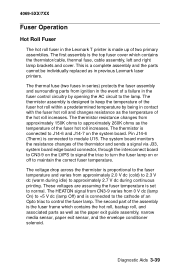
... fuser assembly and surrounding parts from 0 V dc (lamp On) to +5 V dc (lamp Off) and is set to turn the fuser lamp on the system board. The thermistor is the top fuser cover which contains the hot roll, backup roll, and associated parts as well as in previous Lexmark ...printing. Pin J14-6 (Therm) is proportional to the fuser temperature and varies from approximately 150K ohms to the cathode of two primary assemblies. 4069-5XX/7XX Fuser Operation Hot Roll Fuser The hot roll fuser in the Lexmark T printer is a complete assembly and the parts cannot be individually replaced as the ...
... fuser assembly and surrounding parts from 0 V dc (lamp On) to +5 V dc (lamp Off) and is set to turn the fuser lamp on the system board. The thermistor is the top fuser cover which contains the hot roll, backup roll, and associated parts as well as in previous Lexmark ...printing. Pin J14-6 (Therm) is proportional to the fuser temperature and varies from approximately 150K ohms to the cathode of two primary assemblies. 4069-5XX/7XX Fuser Operation Hot Roll Fuser The hot roll fuser in the Lexmark T printer is a complete assembly and the parts cannot be individually replaced as the ...

Service Manual
Page 206
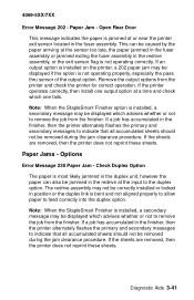
... the printer does not reprint these sheets. This condition can be caused by the paper exiting the input sensor too late or jamming in the fuser assembly prior to remove the job from the finisher. If a job has accumulated in the finisher, then the printer alternately flashes the primary and secondary messages...
... the printer does not reprint these sheets. This condition can be caused by the paper exiting the input sensor too late or jamming in the fuser assembly prior to remove the job from the finisher. If a job has accumulated in the finisher, then the printer alternately flashes the primary and secondary messages...
Service Manual
Page 207
... sheets should not be displayed which one output option at the sensor too late, the paper jammed in the fuser assembly or jammed exiting the fuser assembly in the fuser assembly. If a job has accumulated in the finisher, then the printer alternately flashes the primary and secondary messages to...Options Error Message 230 Paper Jam - If the sheets are removed, then the printer does not reprint these sheets. The redrive assembly may be removed during the jam clearance procedure. Check Duplex Option The paper is most likely jammed in the duplex unit, however ...
... sheets should not be displayed which one output option at the sensor too late, the paper jammed in the fuser assembly or jammed exiting the fuser assembly in the fuser assembly. If a job has accumulated in the finisher, then the printer alternately flashes the primary and secondary messages to...Options Error Message 230 Paper Jam - If the sheets are removed, then the printer does not reprint these sheets. The redrive assembly may be removed during the jam clearance procedure. Check Duplex Option The paper is most likely jammed in the duplex unit, however ...

Service Manual
Page 239
CAUTION: Be sure the fuser assembly has cooled before working on any of the fuser FRUs. Remove the multipurpose tray assembly. 4. Remove the right side frame mounting screws (B) and remove the right side frame. Remove the toner sensor mounting screw (A), disconnect the sensor cable and remove the toner sensor. 6. Disconnect the auto compensator arm bias spring from the right side frame. 5. Repair Information 4-29 Remove the right side cover. 2. 4069-5XX/7XX Right Side Frame 1. Remove the LVPS. 3.
CAUTION: Be sure the fuser assembly has cooled before working on any of the fuser FRUs. Remove the multipurpose tray assembly. 4. Remove the right side frame mounting screws (B) and remove the right side frame. Remove the toner sensor mounting screw (A), disconnect the sensor cable and remove the toner sensor. 6. Disconnect the auto compensator arm bias spring from the right side frame. 5. Repair Information 4-29 Remove the right side cover. 2. 4069-5XX/7XX Right Side Frame 1. Remove the LVPS. 3.

Service Manual
Page 241
... mounting screws (B) and lift the cover from the fuser. Remove the right lamp bracket mounting screws (A). 5. Fuser Detack Fingers 1. Remove the fuser assembly. 2. Remove the fuser detack housing assembly. There is pressure against the other end of the lamp. 4. Be careful not to touch the ...of the lamp therefore care must be used when removing the lamp from the fuser assembly. Remove the fuser assembly. 2. Remove the left lamp bracket and carefully remove the two mounting screws. 4069-5XX/7XX Fuser Cover 1. Note the thermistor cable routing and disconnect the cable. 3. Grip...
... mounting screws (B) and lift the cover from the fuser. Remove the right lamp bracket mounting screws (A). 5. Fuser Detack Fingers 1. Remove the fuser assembly. 2. Remove the fuser detack housing assembly. There is pressure against the other end of the lamp. 4. Be careful not to touch the ...of the lamp therefore care must be used when removing the lamp from the fuser assembly. Remove the fuser assembly. 2. Remove the left lamp bracket and carefully remove the two mounting screws. 4069-5XX/7XX Fuser Cover 1. Note the thermistor cable routing and disconnect the cable. 3. Grip...

Service Manual
Page 242
Remove the fuser cover assembly. 3. Gently pry the detack finger and spring from the housing assembly. Gently apply outward pressure on the left and right fuser side frames (A) to free the fuser frame walls. 5. Remove the fuser assembly. 2. Remove the fuser lamp. Disengage the hot roll bearing clips to release the detack housing assembly (B). 4-32 Service Manual Fuser Detack Housing Assembly 1. Use care when handling the lamp. 4. 4069-5XX/7XX 4.
Remove the fuser cover assembly. 3. Gently pry the detack finger and spring from the housing assembly. Gently apply outward pressure on the left and right fuser side frames (A) to free the fuser frame walls. 5. Remove the fuser assembly. 2. Remove the fuser lamp. Disengage the hot roll bearing clips to release the detack housing assembly (B). 4-32 Service Manual Fuser Detack Housing Assembly 1. Use care when handling the lamp. 4. 4069-5XX/7XX 4.

Service Manual
Page 244
4069-5XX/7XX Fuser Envelope Conditioner Solenoid 1. Remove the fuser assembly. 2. Remove the solenoid from the fuser assembly. Disconnect the solenoid link (B). 4. Remove the solenoid mounting screw (A). 3. Note: Do the "Fuser Solenoid Adjustment" on page 4-3 whenever you replace the fuser solenoid. 4-34 Service Manual
4069-5XX/7XX Fuser Envelope Conditioner Solenoid 1. Remove the fuser assembly. 2. Remove the solenoid from the fuser assembly. Disconnect the solenoid link (B). 4. Remove the solenoid mounting screw (A). 3. Note: Do the "Fuser Solenoid Adjustment" on page 4-3 whenever you replace the fuser solenoid. 4-34 Service Manual

Service Manual
Page 245
... the glass as skin oils and acids can be used when removing the lamp from the fuser. Remove the fuser assembly. 2. Repair Information 4-35 Remove the exit sensor flag assembly. Make sure the narrow media sensor flag is pressure against the other end of the lamp...positioned before snapping the sensor in place. Remove the fuser lamp. 4069-5XX/7XX Fuser Narrow Media Sensor/Flag Assembly 1. Disconnect the sensors from the lower exit guide assembly Fuser Exit Sensor Flag Assembly 1. Disconnect the exit sensor from the fuser assembly. Grip the lamp by the ceramic end piece ...
... the glass as skin oils and acids can be used when removing the lamp from the fuser. Remove the fuser assembly. 2. Repair Information 4-35 Remove the exit sensor flag assembly. Make sure the narrow media sensor flag is pressure against the other end of the lamp...positioned before snapping the sensor in place. Remove the fuser lamp. 4069-5XX/7XX Fuser Narrow Media Sensor/Flag Assembly 1. Disconnect the sensors from the lower exit guide assembly Fuser Exit Sensor Flag Assembly 1. Disconnect the exit sensor from the fuser assembly. Grip the lamp by the ceramic end piece ...

Service Manual
Page 246
... to release the lower exit guide assembly. 4-36 Service Manual Remove the fuser detack housing assembly. 4. Description Fuser Lamp 115V 875W Fuser Lamp 220V 875W Color Code Gold Silver Fuser Lower Exit Guide Assembly 1. The left and right fuser side frames to identify and install the correct lamp. Remove the fuser cover assembly. 3. Remove the fuser assembly. 2. Gently apply outward pressure on...
... to release the lower exit guide assembly. 4-36 Service Manual Remove the fuser detack housing assembly. 4. Description Fuser Lamp 115V 875W Fuser Lamp 220V 875W Color Code Gold Silver Fuser Lower Exit Guide Assembly 1. The left and right fuser side frames to identify and install the correct lamp. Remove the fuser cover assembly. 3. Remove the fuser assembly. 2. Gently apply outward pressure on...


