
Service Manual
Page 4
... Service Check 2-89 Random Marks Service Check 2-90 Residual Image Service Check 2-90 Skew Service Check 2-91 Toner on Backside of Page Service Check 2-91 Uneven Print Density Service Check 2-92 White Lines or Bands Service Check 2-92 White Spots Service Check 2-94 White/Black Lines Service Check 2-95 Serial Port Service Check 2-96 Toner Level Detect Service Check 2-96 iv Service Manual
... Service Check 2-89 Random Marks Service Check 2-90 Residual Image Service Check 2-90 Skew Service Check 2-91 Toner on Backside of Page Service Check 2-91 Uneven Print Density Service Check 2-92 White Lines or Bands Service Check 2-92 White Spots Service Check 2-94 White/Black Lines Service Check 2-95 Serial Port Service Check 2-96 Toner Level Detect Service Check 2-96 iv Service Manual

Service Manual
Page 6
... Removal 4-19 Engine Board Assembly Removal 4-19 HVPS Board Assembly Removal 4-20 Interconnect Board Assembly Removal 4-21 On/Off Coupling Sensor Board Removal 4-21 vi Service Manual
... Removal 4-19 Engine Board Assembly Removal 4-19 HVPS Board Assembly Removal 4-20 Interconnect Board Assembly Removal 4-21 On/Off Coupling Sensor Board Removal 4-21 vi Service Manual

Service Manual
Page 8
... 27: Duplex Option Lower Section 3 7-76 Assembly 28: Cassette Lower Section 4 7-78 Assembly 29: Duplex Option Lower Section 5 7-80 Assembly 30: Miscellaneous 7-84 Index I-1 viii Service Manual
... 27: Duplex Option Lower Section 3 7-76 Assembly 28: Cassette Lower Section 4 7-78 Assembly 29: Duplex Option Lower Section 5 7-80 Assembly 30: Miscellaneous 7-84 Index I-1 viii Service Manual

Service Manual
Page 24
5016-001 xxiv Service Manual
5016-001 xxiv Service Manual

Service Manual
Page 26
..., Letter or A4 - Print Addressability 600 x 600 dpi, 1200 x 1200 dpi Maximum Print Speed (Mono/Color) 16/3 ppm (Letter and A4) 1-2 Service Manual Special Features • Automatic Duplex. • Color Quality Enhancement Technology (CQET). • Automatic color screening selection to 3 impressions - 1.5 duplexed ppm. up.... • Color screens which optimize print quality. 5016-001 Models The 5016-001 printer is available in the following models: Model C710 C710n C710dn Memory 32 MB 32 MB 64 MB INA N/A 10 Base 100T 10 Base 100T Options N/A N/A • Additional 2x250...
..., Letter or A4 - Print Addressability 600 x 600 dpi, 1200 x 1200 dpi Maximum Print Speed (Mono/Color) 16/3 ppm (Letter and A4) 1-2 Service Manual Special Features • Automatic Duplex. • Color Quality Enhancement Technology (CQET). • Automatic color screening selection to 3 impressions - 1.5 duplexed ppm. up.... • Color screens which optimize print quality. 5016-001 Models The 5016-001 printer is available in the following models: Model C710 C710n C710dn Memory 32 MB 32 MB 64 MB INA N/A 10 Base 100T 10 Base 100T Options N/A N/A • Additional 2x250...
Service Manual
Page 28
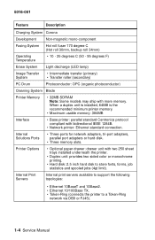
... printer. • Duplex unit: provides two sided color or monochrome printing. • Hard disk: 2.5 inch hard disk to a Token-Ring network via DB9 or FJ45). 1-4 Service Manual 5016-001 Feature Description Charging System Corona Development Non-magnetic mono-component Fusing System Hot roll fuser 170 degree C (Hot roll 30mm, backup roll 34mm...
... printer. • Duplex unit: provides two sided color or monochrome printing. • Hard disk: 2.5 inch hard disk to a Token-Ring network via DB9 or FJ45). 1-4 Service Manual 5016-001 Feature Description Charging System Corona Development Non-magnetic mono-component Fusing System Hot roll fuser 170 degree C (Hot roll 30mm, backup roll 34mm...

Service Manual
Page 30
..., and diagnostic aids to the correct field replaceable unit (FRU) or part. Tools Required For Service • Flat-blade screwdriver • #1 Phillips screwdriver • #2 Phillips screwdriver • 7.0 mm nut driver • 5.5 mm wrench • Needlenose pliers •...8226; Serial wrap plug 1329048 • Twinax/serial debug cable 1381963 • Coax/serial debug cable 1381964 1-6 Service Manual 5016-001 Maintenance Approach The diagnostic information in this manual leads you complete the repair, perform tests as needed to verify the repair. After you to determine the printer...
..., and diagnostic aids to the correct field replaceable unit (FRU) or part. Tools Required For Service • Flat-blade screwdriver • #1 Phillips screwdriver • #2 Phillips screwdriver • 7.0 mm nut driver • 5.5 mm wrench • Needlenose pliers •...8226; Serial wrap plug 1329048 • Twinax/serial debug cable 1381963 • Coax/serial debug cable 1381964 1-6 Service Manual 5016-001 Maintenance Approach The diagnostic information in this manual leads you complete the repair, perform tests as needed to verify the repair. After you to determine the printer...

Service Manual
Page 32
... closed the door switch actuator 1 [C] rotates in the direction of these doors are closed , actuator 1 [C] will not rotate and the switches will not turn on . 1-8 Service Manual If either of arrow [B]. 5016-001 Operational Theory Interlock Mechanism When the front cover assembly, fuser cover or cartridge cover is open . If the front...
... closed the door switch actuator 1 [C] rotates in the direction of these doors are closed , actuator 1 [C] will not rotate and the switches will not turn on . 1-8 Service Manual If either of arrow [B]. 5016-001 Operational Theory Interlock Mechanism When the front cover assembly, fuser cover or cartridge cover is open . If the front...

Service Manual
Page 34
When the sheet of paper is not detected, the sensor turns on. 1-10 Service Manual When the sheet of paper is detected by the sheet bypass paper detect sensor. 5016-001 Detecting paper present A sheet of paper in the sheet bypass tray is detected, the paper detect sensor turns off.
When the sheet of paper is not detected, the sensor turns on. 1-10 Service Manual When the sheet of paper is detected by the sheet bypass paper detect sensor. 5016-001 Detecting paper present A sheet of paper in the sheet bypass tray is detected, the paper detect sensor turns off.

Service Manual
Page 36
It detects Legal, Letter, A4 or B5/EXE. 1-12 Service Manual 5016-001 Detecting paper size Paper size is determined by the paper size detect plate connecting the inner part of the partition plate which detects the paper size turning on the corresponding switch.
It detects Legal, Letter, A4 or B5/EXE. 1-12 Service Manual 5016-001 Detecting paper size Paper size is determined by the paper size detect plate connecting the inner part of the partition plate which detects the paper size turning on the corresponding switch.

Service Manual
Page 38
..., the paper stops at the timing roller and pauses. If the pass thru sensors do not detect paper from the cassette, a paper jam displays. 1-14 Service Manual After a predetermined period of the tray, contacts the release lever which rotates the paper transfer roll allowing it to contact the paper in the tray...
..., the paper stops at the timing roller and pauses. If the pass thru sensors do not detect paper from the cassette, a paper jam displays. 1-14 Service Manual After a predetermined period of the tray, contacts the release lever which rotates the paper transfer roll allowing it to contact the paper in the tray...

Service Manual
Page 40
It detects Legal, Letter, A4 or B5/EXE. 1-16 Service Manual 5016-001 Detecting paper size Paper size is determined by the paper size detect plate connecting the inner part of the partition plate. This plate detects the paper size turning on the corresponding switch.
It detects Legal, Letter, A4 or B5/EXE. 1-16 Service Manual 5016-001 Detecting paper size Paper size is determined by the paper size detect plate connecting the inner part of the partition plate. This plate detects the paper size turning on the corresponding switch.

Service Manual
Page 42
... Operation of transferring from the OPC to the movement of the cam is transmitted in the following order: transfer roller, discharge roller and cleaner. 1-18 Service Manual The cleaner is also detached from the transfer belt at this time. A pin in figure below. Lever 1 and lever 2 are controlled at the position shown...
... Operation of transferring from the OPC to the movement of the cam is transmitted in the following order: transfer roller, discharge roller and cleaner. 1-18 Service Manual The cleaner is also detached from the transfer belt at this time. A pin in figure below. Lever 1 and lever 2 are controlled at the position shown...

Service Manual
Page 44
5016-001 1-20 Service Manual
5016-001 1-20 Service Manual

Service Manual
Page 46
Once the cartridge has been used . (Sensor output at connector) • Will be low "L" when a cartridge is present. 1-22 Service Manual A new cartridge detect sensor: • Will be high "H" when a cartridge has been used the new cartridge detect lever makes a turn and no additional reflections occur. A new cartridge detect sensor installed in the cartridge, reflects light. 5016-001 Toner Cartridge Unit Detecting a new cartridge When initializing, a reflector attached to the new cartridge detect lever installed in the bottom part of the printer, allows the cartridge to be detected.
Once the cartridge has been used . (Sensor output at connector) • Will be low "L" when a cartridge is present. 1-22 Service Manual A new cartridge detect sensor: • Will be high "H" when a cartridge has been used the new cartridge detect lever makes a turn and no additional reflections occur. A new cartridge detect sensor installed in the cartridge, reflects light. 5016-001 Toner Cartridge Unit Detecting a new cartridge When initializing, a reflector attached to the new cartridge detect lever installed in the bottom part of the printer, allows the cartridge to be detected.
Service Manual
Page 48
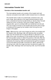
... on the belt is used by the home position sensor to paper, the transfer roller, discharge roller and cleaning roller, touch the transfer belt. 1-24 Service Manual 5016-001 Intermediate Transfer Unit Function of the intermediate transfer unit The intermediate transfer unit consists of the transfer belt, belt cleanser and waster toner...
... on the belt is used by the home position sensor to paper, the transfer roller, discharge roller and cleaning roller, touch the transfer belt. 1-24 Service Manual 5016-001 Intermediate Transfer Unit Function of the intermediate transfer unit The intermediate transfer unit consists of the transfer belt, belt cleanser and waster toner...

Service Manual
Page 50
The transfer roller and discharge roller are rotated by the belt drive gear, rotating the transfer belt. At the same time, the contact pin is shifted by the contact cam. 1-26 Service Manual At the same time the cleaning roller and discharge roller are detached from the transfer belt. 5016-001 Operation of the drive for the intermediate transfer unit The belt gear is rotated by the timing belt and gear. The cleaner lever is shifted by a pin and the cleaning roller is detached from the transfer belt by a lever causing the contact cam to turn.
The transfer roller and discharge roller are rotated by the belt drive gear, rotating the transfer belt. At the same time, the contact pin is shifted by the contact cam. 1-26 Service Manual At the same time the cleaning roller and discharge roller are detached from the transfer belt. 5016-001 Operation of the drive for the intermediate transfer unit The belt gear is rotated by the timing belt and gear. The cleaner lever is shifted by a pin and the cleaning roller is detached from the transfer belt by a lever causing the contact cam to turn.

Service Manual
Page 52
... and surrounding parts are printed, a warning displays. When additional sheets are printed, the printer stops until the unit is placed, repeat the previous step. 1-28 Service Manual Note: The fuse will generally blow after primary power has been applied following the printing of two or three sheets of paper are 70 degrees...
... and surrounding parts are printed, a warning displays. When additional sheets are printed, the printer stops until the unit is placed, repeat the previous step. 1-28 Service Manual Note: The fuse will generally blow after primary power has been applied following the printing of two or three sheets of paper are 70 degrees...

Service Manual
Page 54
... receive the paper. When the leading edge of the motor is switched to the storage area in the lower unit through the rear unit. 1-30 Service Manual When the paper reaches the upper paper pass sensor, through the fuser roller. At the same time, the lower unit motor begins rotating in the...
... receive the paper. When the leading edge of the motor is switched to the storage area in the lower unit through the rear unit. 1-30 Service Manual When the paper reaches the upper paper pass sensor, through the fuser roller. At the same time, the lower unit motor begins rotating in the...

Service Manual
Page 56
... the setting is four pages The back page of the second page and finally the second page, as it is finished, exits the printer. 1-32 Service Manual The first page waiting in the lower unit is received in the upper unit through the storage, reverse and skew correction mechanisms in the lower...
... the setting is four pages The back page of the second page and finally the second page, as it is finished, exits the printer. 1-32 Service Manual The first page waiting in the lower unit is received in the upper unit through the storage, reverse and skew correction mechanisms in the lower...


