Service Manual
Page 39
... with the replacement specified photoconductor unit. • If the problem persists, replace the system card. See "Front door assembly removal" on page 4-40. See "Bump aligner motor removal" on page 4-55. • Replace the transfer belt assembly. See "System card removal" on page 4-91. • If the problem persists, replace the system card. See...
... with the replacement specified photoconductor unit. • If the problem persists, replace the system card. See "Front door assembly removal" on page 4-40. See "Bump aligner motor removal" on page 4-55. • Replace the transfer belt assembly. See "System card removal" on page 4-91. • If the problem persists, replace the system card. See...

Service Manual
Page 60
... service check Step Questions / actions 1 Turn the printer off , and remove the rear cover. Is the cable damaged? 2 Replace the transfer belt assembly. No Go to step 2. See "System card (network)-models C52x" on page 4-91. Go to the system card, the cable for... for the location of JTRANS1. Check the connector JTRANS1 for proper connection to step 2. 2 Replace the transfer belt assembly. Replace the printhead. Replace the front door assembly. Problem solved. See "Transfer belt removal" on page 4-74. Is the cable damaged? 2 Replace the system card. Problem solved. See...
... service check Step Questions / actions 1 Turn the printer off , and remove the rear cover. Is the cable damaged? 2 Replace the transfer belt assembly. No Go to step 2. See "System card (network)-models C52x" on page 4-91. Go to the system card, the cable for... for the location of JTRANS1. Check the connector JTRANS1 for proper connection to step 2. 2 Replace the transfer belt assembly. Replace the printhead. Replace the front door assembly. Problem solved. See "Transfer belt removal" on page 4-74. Is the cable damaged? 2 Replace the system card. Problem solved. See...

Service Manual
Page 71
...in question. See "General motor tests" on page 4-51. Go to the transfer belt assembly. model C53x only" on page 3-8. Does this fix the problem? 3 Yes Go to step 2. See "Transfer contact assembly removal" on page 4-62. Is a problem found? 4 Reseat the JHVPS ...connector. Problem solved. Does this fix the problem? See "Electrophotographic (EP) drive assembly removal- Transfer belt high voltage path (typical 4X) Replace the spring or the transfer contact assembly. No Remove the packing material. 5022-xxx Step Questions / actions Yes 2 Replace the PC ...
...in question. See "General motor tests" on page 4-51. Go to the transfer belt assembly. model C53x only" on page 3-8. Does this fix the problem? 3 Yes Go to step 2. See "Transfer contact assembly removal" on page 4-62. Is a problem found? 4 Reseat the JHVPS ...connector. Problem solved. Does this fix the problem? See "Electrophotographic (EP) drive assembly removal- Transfer belt high voltage path (typical 4X) Replace the spring or the transfer contact assembly. No Remove the packing material. 5022-xxx Step Questions / actions Yes 2 Replace the PC ...

Service Manual
Page 73
Check the EP drive assembly and transfer belt assembly for correct operation. Is the distance between repeating bands. Print quality-horizontal line The photoconductor unit is usually caused by incorrect feeding from one of ... Print quality-blurred or fuzzy print Blurred or fuzzy print is defective. Blurred print can also be caused by a problem in the EP drive assembly or in the transfer belt assembly. Print quality-half-color page A photoconductor unit is not properly seated. Reset the specific photoconductor unit. Yes Replace the print cartridge. See "Photoconductor...
Check the EP drive assembly and transfer belt assembly for correct operation. Is the distance between repeating bands. Print quality-horizontal line The photoconductor unit is usually caused by incorrect feeding from one of ... Print quality-blurred or fuzzy print Blurred or fuzzy print is defective. Blurred print can also be caused by a problem in the EP drive assembly or in the transfer belt assembly. Print quality-half-color page A photoconductor unit is not properly seated. Reset the specific photoconductor unit. Yes Replace the print cartridge. See "Photoconductor...
Service Manual
Page 74
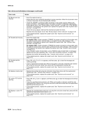
...2 Is there any loose or foreign material on the cartridge roll? 3 Is there any toner contamination on the transfer belt? Go to step 2. Replace the transfer belt. Yes Replace the fuser. Replace the print cartridge. Print quality-residual image Service tip: Install a new print...the printer and attaching to the photoconductor unit, developer roll, or transfer belt. No Contact your next level of support. Step Questions / actions 1 Is there any loose or foreign material on the fuser assembly? Diagnostic information 2-59 See "Photoconductor unit removal" on page 4-60...
...2 Is there any loose or foreign material on the cartridge roll? 3 Is there any toner contamination on the transfer belt? Go to step 2. Replace the transfer belt. Yes Replace the fuser. Replace the print cartridge. Print quality-residual image Service tip: Install a new print...the printer and attaching to the photoconductor unit, developer roll, or transfer belt. No Contact your next level of support. Step Questions / actions 1 Is there any loose or foreign material on the fuser assembly? Diagnostic information 2-59 See "Photoconductor unit removal" on page 4-60...

Service Manual
Page 79
Tray 1 Tests tray 1 motor located in the paper pick mechanism. Transfer Tests the transfer belt assembly motor located on page 3-8. See "General motor tests" on the EP drive assembly. Fuser Tests the fuser motor. See "General motor tests" on the EP drive assembly. Tray 2 (if installed) Tests tray 2 motor located in the paper pick mechanism. Top Cartridge...
Tray 1 Tests tray 1 motor located in the paper pick mechanism. Transfer Tests the transfer belt assembly motor located on page 3-8. See "General motor tests" on the EP drive assembly. Fuser Tests the fuser motor. See "General motor tests" on the EP drive assembly. Tray 2 (if installed) Tests tray 2 motor located in the paper pick mechanism. Top Cartridge...
Service Manual
Page 92
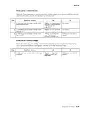
... 1. The display shows each one of the sensors, one line at a time, and the current state of paper between the TPS and the transfer belt. Use the following table to exit the test. Sensor Possible values Sensor activation Fuser Exit (paper Open/Closed exit) Inner Door (front Open/Closed... access door) Input Open/Closed Narrow Media (transparency) Open/Closed TPS Toner C Toner K Toner M Toner Y Top Door (top access cover assembly) Waste Toner Open/Closed Open/Closed Open/Closed Open/Closed Open/Closed Open/Closed OK/Full Open the top access cover. The sensor should change...
... 1. The display shows each one of the sensors, one line at a time, and the current state of paper between the TPS and the transfer belt. Use the following table to exit the test. Sensor Possible values Sensor activation Fuser Exit (paper Open/Closed exit) Inner Door (front Open/Closed... access door) Input Open/Closed Narrow Media (transparency) Open/Closed TPS Toner C Toner K Toner M Toner Y Top Door (top access cover assembly) Waste Toner Open/Closed Open/Closed Open/Closed Open/Closed Open/Closed Open/Closed OK/Full Open the top access cover. The sensor should change...

Service Manual
Page 110
The media movement is picked from (Tray 1, Tray 2, or, the MPF); it will enter the electrophotographic process at the bump aligner drive. It does not matter where the media comes from the input source and fed to the transfer belt. 500-sheet assembly pick tire Bump aligner roll Pick tire Backup aligner roll MPF pick tire Diagnostic aids 3-33 The bump aligner motor drives the bump aligner roll which feeds the paper to the bump aligner roll. 5022-xxx Print media transport The print media is detected by a sensor located in the paper pick mechanism.
The media movement is picked from (Tray 1, Tray 2, or, the MPF); it will enter the electrophotographic process at the bump aligner drive. It does not matter where the media comes from the input source and fed to the transfer belt. 500-sheet assembly pick tire Bump aligner roll Pick tire Backup aligner roll MPF pick tire Diagnostic aids 3-33 The bump aligner motor drives the bump aligner roll which feeds the paper to the bump aligner roll. 5022-xxx Print media transport The print media is detected by a sensor located in the paper pick mechanism.

Service Manual
Page 117
Outside Inside Transfer belt motor Coupler Fuser drive The fuser drive (motor) is open, the coupler for the transfer belt disengages. When the top access door is built into the fuser assembly and drives the fuser rollers to turn. 3-40 Service Manual 5022-xxx Transfer belt drive The transfer belt unit receives drive from a motor located on the EP drive assembly.
Outside Inside Transfer belt motor Coupler Fuser drive The fuser drive (motor) is open, the coupler for the transfer belt disengages. When the top access door is built into the fuser assembly and drives the fuser rollers to turn. 3-40 Service Manual 5022-xxx Transfer belt drive The transfer belt unit receives drive from a motor located on the EP drive assembly.
Service Manual
Page 130
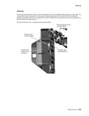
... in the waste toner container located next to the belt inside the transfer belt assembly. Any waste toner that is scraped off of the electrophotographic process cycle. Photoconductor drum cleaning blade Transfer belt cleaning blade Transfer belt waste toner container Transfer belt cleaning shaft Diagnostic aids 3-53 5022-xxx Cleaning The transfer belt and photoconductor drum are cleaned at the end of...
... in the waste toner container located next to the belt inside the transfer belt assembly. Any waste toner that is scraped off of the electrophotographic process cycle. Photoconductor drum cleaning blade Transfer belt cleaning blade Transfer belt waste toner container Transfer belt cleaning shaft Diagnostic aids 3-53 5022-xxx Cleaning The transfer belt and photoconductor drum are cleaned at the end of...
Service Manual
Page 149
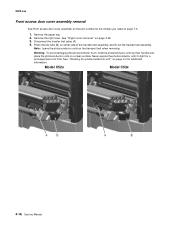
... photoconductor units on either side of time. Disconnect the transfer belt cable (A). 4. Note: Leave the photoconductor units on page 7-3. 1. 5022-xxx Front access door cover assembly removal See Front access door cover assembly for the part number for the models you need on... the transport belt when removing. See "Handing the photoconductor unit" on page 4-26. 3. Remove the right cover. See "Right cover removal" on page 4-2 for a prolonged period of the transfer belt assembly, and lift out the transfer belt assembly. Never expose the photoconductor units...
... photoconductor units on either side of time. Disconnect the transfer belt cable (A). 4. Note: Leave the photoconductor units on page 7-3. 1. 5022-xxx Front access door cover assembly removal See Front access door cover assembly for the part number for the models you need on... the transport belt when removing. See "Handing the photoconductor unit" on page 4-26. 3. Remove the right cover. See "Right cover removal" on page 4-2 for a prolonged period of the transfer belt assembly, and lift out the transfer belt assembly. Never expose the photoconductor units...

Service Manual
Page 207
... rendered inoperable. 1. Press the two tabs (B) on page 4-15. 3. C52x C53x A B A B 5. Never expose the photoconductor units to light for a prolonged period of the transfer belt assembly, and lift out the transfer belt assembly. Remove the toner cartridges. 2. See "System card support shield removal" on page 7-9 for additional information. See "Fuser cable cover removal" on a clean surface...
... rendered inoperable. 1. Press the two tabs (B) on page 4-15. 3. C52x C53x A B A B 5. Never expose the photoconductor units to light for a prolonged period of the transfer belt assembly, and lift out the transfer belt assembly. Remove the toner cartridges. 2. See "System card support shield removal" on page 7-9 for additional information. See "Fuser cable cover removal" on a clean surface...
Service Manual
Page 224
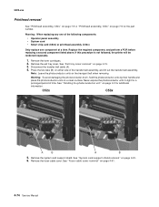
... expose the photoconductor units to the new one, the alignment of time. Select Color Alignment. 5022-xxx Transfer belt removal See "Transfer belt assembly, C52x" on page 7-15 or "Transfer belt assembly, C53x" on either side of the transfer belt assembly, and lift out the transfer belt assembly. Press the two tabs (B) on page 7-15 for a prolonged period of the toner cartridges and photoconductor...
... expose the photoconductor units to the new one, the alignment of time. Select Color Alignment. 5022-xxx Transfer belt removal See "Transfer belt assembly, C52x" on page 7-15 or "Transfer belt assembly, C53x" on either side of the transfer belt assembly, and lift out the transfer belt assembly. Press the two tabs (B) on page 7-15 for a prolonged period of the toner cartridges and photoconductor...

Service Manual
Page 243
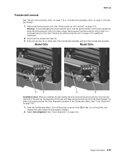
... (A). 4. See "Right cover removal" on either side of time. Never expose the photoconductor units to light for a prolonged period of the transfer belt assembly, and lift out the transfer belt assembly. Note: Leave the photoconductor units on a clean surface. Model C52x Model C53x A B A B 4-16 Service Manual Remove the paper tray. 2. Warning: To avoid damaging the photoconductor...
... (A). 4. See "Right cover removal" on either side of time. Never expose the photoconductor units to light for a prolonged period of the transfer belt assembly, and lift out the transfer belt assembly. Note: Leave the photoconductor units on a clean surface. Model C52x Model C53x A B A B 4-16 Service Manual Remove the paper tray. 2. Warning: To avoid damaging the photoconductor...
Service Manual
Page 301
... Manual Never expose the photoconductor units to light for additional information. See "Fuser cable cover removal" on page 4-2 for a prolonged period of the transfer belt assembly, and lift out the transfer belt assembly. Remove the toner cartridges. 2. See "System card support shield removal" on page 4-15. 3. Replace the required component, and perform a POR before replacing a second...
... Manual Never expose the photoconductor units to light for additional information. See "Fuser cable cover removal" on page 4-2 for a prolonged period of the transfer belt assembly, and lift out the transfer belt assembly. Remove the toner cartridges. 2. See "System card support shield removal" on page 4-15. 3. Replace the required component, and perform a POR before replacing a second...

Service Manual
Page 318
... one to light for additional information. 2. Press the two tabs (B) on a clean surface. Select Color Alignment. Disconnect the transfer belt cable (A). 3. Warning: To avoid damaging the photoconductor drum, hold release the buttons when the clock graphic displays.) 2. For better... the photoconductor units by their handle and place the photoconductor units on either side of time. 5022-xxx Transfer belt removal See "Transfer belt assembly, C52x" on page 7-15 or "Transfer belt assembly, C53x" on page 4-70. See "Photoconductor unit removal" on page 7-15 for the part number....
... one to light for additional information. 2. Press the two tabs (B) on a clean surface. Select Color Alignment. Disconnect the transfer belt cable (A). 3. Warning: To avoid damaging the photoconductor drum, hold release the buttons when the clock graphic displays.) 2. For better... the photoconductor units by their handle and place the photoconductor units on either side of time. 5022-xxx Transfer belt removal See "Transfer belt assembly, C52x" on page 7-15 or "Transfer belt assembly, C53x" on page 4-70. See "Photoconductor unit removal" on page 7-15 for the part number....

Service Manual
Page 346
The following maintenance items are available for the customer: Maintenance items Description Fuser assembly, 115 V Fuser assembly, 230 V Fuser assembly, 100 V Transfer belt assembly, C52x Transfer belt assembly, C53x Part number 40X3569 40X3570 40X3571 40X1401 40X3572 Preventive maintenance 6-1 The fuser assembly and the transfer roll should be changed at 120K page count interval. 6. Preventive maintenance 5022-xxx Scheduled maintenance The operator panel displays 80 Replace Fuser at this interval to maintain the print quality and reliability of the printer.
The following maintenance items are available for the customer: Maintenance items Description Fuser assembly, 115 V Fuser assembly, 230 V Fuser assembly, 100 V Transfer belt assembly, C52x Transfer belt assembly, C53x Part number 40X3569 40X3570 40X3571 40X1401 40X3572 Preventive maintenance 6-1 The fuser assembly and the transfer roll should be changed at 120K page count interval. 6. Preventive maintenance 5022-xxx Scheduled maintenance The operator panel displays 80 Replace Fuser at this interval to maintain the print quality and reliability of the printer.

Service Manual
Page 362
.../C532dn/ C534n/C534dn Tray assembly, 500-sheet, C522n/C524/C524n/C524dn Tray assembly, 550-sheet, C532n/C532dn/C534n/C534dn MPF paper tray assembly, 250-sheet, C524/C524n/C524dn Paper tray assembly, single feeder, C520n/C522n MPF paper tray assembly, 250-sheet, C530dn/C532dn/C534dn Paper tray assembly, single feeder, C532n, C534n Transfer belt assembly, C52x Transfer belt assembly, C53x Power cord-USA...
.../C532dn/ C534n/C534dn Tray assembly, 500-sheet, C522n/C524/C524n/C524dn Tray assembly, 550-sheet, C532n/C532dn/C534n/C534dn MPF paper tray assembly, 250-sheet, C524/C524n/C524dn Paper tray assembly, single feeder, C520n/C522n MPF paper tray assembly, 250-sheet, C530dn/C532dn/C534dn Paper tray assembly, single feeder, C532n, C534n Transfer belt assembly, C52x Transfer belt assembly, C53x Power cord-USA...

Service Manual
Page 374
.../C524dn/C534/C534dn 7-20 MarkNet N8050 802.11g wireless print server (US/Americas), C524/C524dn/C534n/C534dn 7-20 Transfer belt assembly, C52x 6-1, 7-15 MPF paper tray assembly, 250-sheet, C524/C524n/C524dn 7-15 Paper pick mechanism assembly, C52x 7-5 EP drive assembly, C52x 7-7 Smart chip card, C52x only 7-9 High voltage power supply, C52x 7-11 Top access cover...
.../C524dn/C534/C534dn 7-20 MarkNet N8050 802.11g wireless print server (US/Americas), C524/C524dn/C534n/C534dn 7-20 Transfer belt assembly, C52x 6-1, 7-15 MPF paper tray assembly, 250-sheet, C524/C524n/C524dn 7-15 Paper pick mechanism assembly, C52x 7-5 EP drive assembly, C52x 7-7 Smart chip card, C52x only 7-9 High voltage power supply, C52x 7-11 Top access cover...
Service Manual
Page 375
.../C524dn/C534n/C534dn/C534dtn 7-20 Forms card, C524/C524n/C524dn 7-20 Bar code card, C524/C524n/C524dn 7-20 Fuser assembly, 115 V 6-1, 7-15 Fuser assembly, 230 V 6-1, 7-15 Fuser assembly, 100 V 6-1, 7-15 Transfer belt assembly, C53x 6-1, 7-15 Paper pick mechanism assembly, C53x 7-5 Low voltage power supply, 115/230 V 7-7 System card (network), C530dn/C532n/C532dn 7-9 System card (network), C534n 7-9 System...
.../C524dn/C534n/C534dn/C534dtn 7-20 Forms card, C524/C524n/C524dn 7-20 Bar code card, C524/C524n/C524dn 7-20 Fuser assembly, 115 V 6-1, 7-15 Fuser assembly, 230 V 6-1, 7-15 Fuser assembly, 100 V 6-1, 7-15 Transfer belt assembly, C53x 6-1, 7-15 Paper pick mechanism assembly, C53x 7-5 Low voltage power supply, 115/230 V 7-7 System card (network), C530dn/C532n/C532dn 7-9 System card (network), C534n 7-9 System...


