User's Guide
Page 2
...The following paragraph does not apply to any accompanying documentation provided under this agreement are commercial computer software and documentation developed exclusively at any time. Lexmark may not apply to you . PCL® is Hewlett-Packard Company's designation of a set up this ...Changes are periodically made at private expense. Comments about this publication to the information herein; You can purchase additional copies of Lexmark International, Inc., registered in the United States and/or other products, programs, or services, except those described in the operating...
...The following paragraph does not apply to any accompanying documentation provided under this agreement are commercial computer software and documentation developed exclusively at any time. Lexmark may not apply to you . PCL® is Hewlett-Packard Company's designation of a set up this ...Changes are periodically made at private expense. Comments about this publication to the information herein; You can purchase additional copies of Lexmark International, Inc., registered in the United States and/or other products, programs, or services, except those described in the operating...
User's Guide
Page 135
...be made available with the printer, and click Contact Lexmark. To obtain source code files for the GNU licensed software, contact technical support. Notices Licensing notice The printer resident software contains software developed and copyrighted by these third-party licenses is similarly... provided without warranty. you any rights to the Lexmark copyrighted software in the en\OpenSource\APSL directory. These licenses do ...
...be made available with the printer, and click Contact Lexmark. To obtain source code files for the GNU licensed software, contact technical support. Notices Licensing notice The printer resident software contains software developed and copyrighted by these third-party licenses is similarly... provided without warranty. you any rights to the Lexmark copyrighted software in the en\OpenSource\APSL directory. These licenses do ...

Menus and Messages Guide
Page 2
...those expressly designated by calling 1-800-553-9727. PostScript® is a registered trademark of their respective owners. © 2005 Lexmark International, Inc. Eurostile Geneva Nebiolo Apple Computer, Inc. Comments about this statement may be incorporated in conjunction with diamond design, ...Apple Computer, Inc. Clarendon Linotype-Hell AG and/or its subsidiaries Other trademarks are commercial computer software and documentation developed exclusively at any obligation to this agreement are the property of the Hewlett-Packard Company. You can purchase additional ...
...those expressly designated by calling 1-800-553-9727. PostScript® is a registered trademark of their respective owners. © 2005 Lexmark International, Inc. Eurostile Geneva Nebiolo Apple Computer, Inc. Comments about this statement may be incorporated in conjunction with diamond design, ...Apple Computer, Inc. Clarendon Linotype-Hell AG and/or its subsidiaries Other trademarks are commercial computer software and documentation developed exclusively at any obligation to this agreement are the property of the Hewlett-Packard Company. You can purchase additional ...

Service Manual
Page 20
... turns on . 2. Diagnostic information 2-5 The LED turns on . 14. A clock face appears on , it performs a Power-On Self Test. The EP drive assembly drives the developer shaft located in the toner cartridge. 15.
... turns on . 2. Diagnostic information 2-5 The LED turns on . 14. A clock face appears on , it performs a Power-On Self Test. The EP drive assembly drives the developer shaft located in the toner cartridge. 15.
Service Manual
Page 70
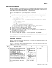
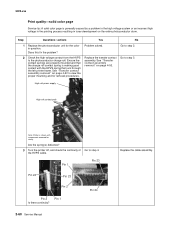
...Inspect the transfer belt for damage. Select Supplies Menu, and press . 3. Diagnostic information 2-55 With the customer's permission, you want to install a developer (toner) cartridge or photoconductor unit. Color Correction: Set to see if the problem remains. 6. Has the photoconductor unit been recently replaced? 1. Any... menus. To reset unit from the connector to 1200 dpi (print quality problems should be caused by rough papers, non-Lexmark toner cartridges or if the media texture is set to zero out all supplies. Ask the customer if the photoconductor unit ...
...Inspect the transfer belt for damage. Select Supplies Menu, and press . 3. Diagnostic information 2-55 With the customer's permission, you want to install a developer (toner) cartridge or photoconductor unit. Color Correction: Set to see if the problem remains. 6. Has the photoconductor unit been recently replaced? 1. Any... menus. To reset unit from the connector to 1200 dpi (print quality problems should be caused by rough papers, non-Lexmark toner cartridges or if the media texture is set to zero out all supplies. Ask the customer if the photoconductor unit ...

Service Manual
Page 73
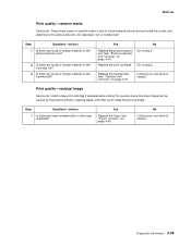
...Yes Go to ensure they are not bent, corroded, or damaged. Replace the LVPS. Print quality-missing image at edge Reseat the developer cartridge. Print quality-horizontal line The photoconductor unit is not properly seated. Does this fix the problem? see "Low voltage power supply... (LVPS) removal" on page 4-70. If the problem persists, replace the developer cartridge. No Replace the print cartridge. 2-58 Service Manual Print quality-half-color page A photoconductor unit is defective. Yes Replace the print cartridge....
...Yes Go to ensure they are not bent, corroded, or damaged. Replace the LVPS. Print quality-missing image at edge Reseat the developer cartridge. Print quality-horizontal line The photoconductor unit is not properly seated. Does this fix the problem? see "Low voltage power supply... (LVPS) removal" on page 4-70. If the problem persists, replace the developer cartridge. No Replace the print cartridge. 2-58 Service Manual Print quality-half-color page A photoconductor unit is defective. Yes Replace the print cartridge....
Service Manual
Page 74
Go to the photoconductor unit, developer roll, or transfer belt. Yes Replace the fuser. Replace the transfer belt. Residual image can be caused by the photoconductor, cleaning blade, and other parts ...
Go to the photoconductor unit, developer roll, or transfer belt. Yes Replace the fuser. Replace the transfer belt. Residual image can be caused by the photoconductor, cleaning blade, and other parts ...
Service Manual
Page 75
... the cable assembly. High volt power supply High volt contact path Note: Printer is making good contact with components removed for the color in toner development on page 4-92. See "Transfer contact assembly removal" on the entire photoconductor drum. Does this fix the problem? 5022-xxx Print quality-solid color page...
... the cable assembly. High volt power supply High volt contact path Note: Printer is making good contact with components removed for the color in toner development on page 4-92. See "Transfer contact assembly removal" on the entire photoconductor drum. Does this fix the problem? 5022-xxx Print quality-solid color page...

Service Manual
Page 76
See "High voltage power supply (HVPS) removal" on page 4-79. Did this solve the problem? Problem solved. Print quality-vertical banding Replace the developer cartridge. 5022-xxx No Replace the system card. Diagnostic information 2-61 Step Questions / actions Yes 4 Replace the HVPS. See "System card removal" on page 4-62.
See "High voltage power supply (HVPS) removal" on page 4-79. Did this solve the problem? Problem solved. Print quality-vertical banding Replace the developer cartridge. 5022-xxx No Replace the system card. Diagnostic information 2-61 Step Questions / actions Yes 4 Replace the HVPS. See "System card removal" on page 4-62.

Service Manual
Page 121
During the print process, an image is the brain of the system card converts the data into a raster image and feeds this data along with control information to the system card. The raster image processor (RIP) portion of the printer. 5022-xxx Electrophotographic (EP) process Main components High voltage power supply Fuser Printhead Developer (toner) cartridge Transfer belt Photoconductor belt System card The system card is sent from a computer to the printhead. 3-44 Service Manual
During the print process, an image is the brain of the system card converts the data into a raster image and feeds this data along with control information to the system card. The raster image processor (RIP) portion of the printer. 5022-xxx Electrophotographic (EP) process Main components High voltage power supply Fuser Printhead Developer (toner) cartridge Transfer belt Photoconductor belt System card The system card is sent from a computer to the printhead. 3-44 Service Manual

Service Manual
Page 122
...8226; The photoconductor drum located in the photoconductor unit • The toner adder roller (TAR) located in the toner cartridge • The developer roll located in the toner cartridge • The doctor blade located in the toner cartridge • The four transfer rolls located in the ...transfer belt Printhead assembly The printhead receives control and image data from the cartridge developer roller and then transferring the image to prepare it for the latent image "drawn" by the laser. The primary function of a laser...
...8226; The photoconductor drum located in the photoconductor unit • The toner adder roller (TAR) located in the toner cartridge • The developer roll located in the toner cartridge • The doctor blade located in the toner cartridge • The four transfer rolls located in the ...transfer belt Printhead assembly The printhead receives control and image data from the cartridge developer roller and then transferring the image to prepare it for the latent image "drawn" by the laser. The primary function of a laser...

Service Manual
Page 124
... high voltage current to flow from the HVPS. High voltage power supply Cleaner blade high voltage contact path Toner add roll high voltage contact path Developer roll high voltage contact path Diagnostic aids 3-47 These three parts are provided high voltage from the HVPS to provide a good flow. 5022-xxx Toner... properly touching to the toner cartridge. If not, print quality problems will occur. The toner cartridge contains three parts that are : the doctor blade, the developer roll, and the toner adder roll (TAR).
... high voltage current to flow from the HVPS. High voltage power supply Cleaner blade high voltage contact path Toner add roll high voltage contact path Developer roll high voltage contact path Diagnostic aids 3-47 These three parts are provided high voltage from the HVPS to provide a good flow. 5022-xxx Toner... properly touching to the toner cartridge. If not, print quality problems will occur. The toner cartridge contains three parts that are : the doctor blade, the developer roll, and the toner adder roll (TAR).
Service Manual
Page 127
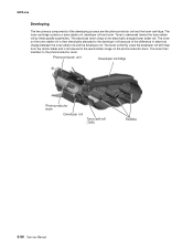
... image on the toner adder roll is then electrically attracted to the electrically charged toner adder roll. The toner uniformly coats the developer roll with help from the doctor blade and is advanced toward the toner adder roll by three paddle assemblies. The advanced toner ...clings to the developer roll because of the developing process are the photoconductor unit and the toner cartridge. 5022-xxx Developing The two primary components of the difference in electrical charge between the toner adder roll...
... image on the toner adder roll is then electrically attracted to the electrically charged toner adder roll. The toner uniformly coats the developer roll with help from the doctor blade and is advanced toward the toner adder roll by three paddle assemblies. The advanced toner ...clings to the developer roll because of the developing process are the photoconductor unit and the toner cartridge. 5022-xxx Developing The two primary components of the difference in electrical charge between the toner adder roll...

Service Manual
Page 183
Note: When retracted, the upper (F) and lower retraction plates (G) will be fully forward. If not, slide the upper retraction plate forward until the EP drive retracts and is retracted when installing the new EP drive assembly. 5022-xxx Installation note: Ensure that the top access door is open and EP drive is disengaged from the developers. 4-50 Service Manual
Note: When retracted, the upper (F) and lower retraction plates (G) will be fully forward. If not, slide the upper retraction plate forward until the EP drive retracts and is retracted when installing the new EP drive assembly. 5022-xxx Installation note: Ensure that the top access door is open and EP drive is disengaged from the developers. 4-50 Service Manual

Service Manual
Page 186
Note: When retracted, upper (F) and lower retraction plates (G) will be fully forward. Repair information 4-53 If not, slide the upper retraction plate forward until the EP drive retracts and is retracted when installing the new EP drive assembly. 5022-xxx Installation note: Ensure that the top access door is open and the EP drive is disengaged from the developers.
Note: When retracted, upper (F) and lower retraction plates (G) will be fully forward. Repair information 4-53 If not, slide the upper retraction plate forward until the EP drive retracts and is retracted when installing the new EP drive assembly. 5022-xxx Installation note: Ensure that the top access door is open and the EP drive is disengaged from the developers.

Service Manual
Page 277
5022-xxx Installation note: Ensure that the top access door is open and EP drive is disengaged from the developers. 4-50 Service Manual If not, slide the upper retraction plate forward until the EP drive retracts and is retracted when installing the new EP drive assembly. Note: When retracted, the upper (F) and lower retraction plates (G) will be fully forward.
5022-xxx Installation note: Ensure that the top access door is open and EP drive is disengaged from the developers. 4-50 Service Manual If not, slide the upper retraction plate forward until the EP drive retracts and is retracted when installing the new EP drive assembly. Note: When retracted, the upper (F) and lower retraction plates (G) will be fully forward.

Service Manual
Page 280
If not, slide the upper retraction plate forward until the EP drive retracts and is retracted when installing the new EP drive assembly. Repair information 4-53 5022-xxx Installation note: Ensure that the top access door is open and the EP drive is disengaged from the developers. Note: When retracted, upper (F) and lower retraction plates (G) will be fully forward.
If not, slide the upper retraction plate forward until the EP drive retracts and is retracted when installing the new EP drive assembly. Repair information 4-53 5022-xxx Installation note: Ensure that the top access door is open and the EP drive is disengaged from the developers. Note: When retracted, upper (F) and lower retraction plates (G) will be fully forward.

Service Manual
Page 364
Assembly 8: Contact springs Index 8-1 P/N 40X1434 Units/ mach 1 Units/ FRU 1 Description Contact springs kit, including: • A-Torsion PCD contact spring (4) • B-Torsion CR contact spring (4) • C-Contact spring cap (4) • D-Charge roll contact spring (8) • E-HVPS TAR contact spring (4) • F-HVPS doctor/developer contact spring (8) 5022-xxx Parts catalog 7-17
Assembly 8: Contact springs Index 8-1 P/N 40X1434 Units/ mach 1 Units/ FRU 1 Description Contact springs kit, including: • A-Torsion PCD contact spring (4) • B-Torsion CR contact spring (4) • C-Contact spring cap (4) • D-Charge roll contact spring (8) • E-HVPS TAR contact spring (4) • F-HVPS doctor/developer contact spring (8) 5022-xxx Parts catalog 7-17

Service Manual
Page 369
... 3-55 5 V interlock switch 3-54 electrophotographic (EP) drive assembly locations 5-3 parts catalog 7-6 removal-C52x 4-48 removal-C53x 4-51 electrophotographic (EP) process 3-44 charging 3-46 cleaning 3-53 developing 3-50 exposing 3-49 fusing 3-52 main components 3-44 transferring 3-51 Energy Conserve 3-23 Enforce Color Order 3-24 engine setting 3-16 Env Prompts 3-25 envelopes 1-8 error...
... 3-55 5 V interlock switch 3-54 electrophotographic (EP) drive assembly locations 5-3 parts catalog 7-6 removal-C52x 4-48 removal-C53x 4-51 electrophotographic (EP) process 3-44 charging 3-46 cleaning 3-53 developing 3-50 exposing 3-49 fusing 3-52 main components 3-44 transferring 3-51 Energy Conserve 3-23 Enforce Color Order 3-24 engine setting 3-16 Env Prompts 3-25 envelopes 1-8 error...

Service Manual
Page 372
... 3-10, 3-21 Quick Test 3-6 quick test (duplex) 3-12 theory electrical interlock 24 V interlock switch 3-55 5 V interlock switch 3-54 electrophotographic (EP) process charging 3-46 cleaning 3-53 developing 3-50 exposing 3-49 fusing 3-52 main components 3-44 transferring 3-51 electrophotographic process (EP) 3-44 paper path 3-30 main components 3-32 mechanical drive 3-37 paper sensing...
... 3-10, 3-21 Quick Test 3-6 quick test (duplex) 3-12 theory electrical interlock 24 V interlock switch 3-55 5 V interlock switch 3-54 electrophotographic (EP) process charging 3-46 cleaning 3-53 developing 3-50 exposing 3-49 fusing 3-52 main components 3-44 transferring 3-51 electrophotographic process (EP) 3-44 paper path 3-30 main components 3-32 mechanical drive 3-37 paper sensing...


