Service Manual
Page 4
...Passage Test ...2-48 Operator Menu Disabled ...2-48 Diagnostic Mode...2-48 Diagnostic Menu Group ...2-48 Setting Printer Registration ...2-50 Print Tests ...2-50 Quality Pages ...2-51 Clean Engine Test ...2-51 LCD Hardware... for Disassembly and Cleaning ...3-1 Instructions for Handling the PWBs with MOS ICs...3-1 Precautions for Handling the Drum Cartridge ...3-2 Parts not to be touched ...3-2 Precautions for Handling the Laser Equipment ...3-3 Adjustment Procedures ...3-3 Registration Adjustment ...3-3 Rack Lever Solenoid Adjustment ...3-5 Removal Procedures ...3-5 Outer Cover Removals...
...Passage Test ...2-48 Operator Menu Disabled ...2-48 Diagnostic Mode...2-48 Diagnostic Menu Group ...2-48 Setting Printer Registration ...2-50 Print Tests ...2-50 Quality Pages ...2-51 Clean Engine Test ...2-51 LCD Hardware... for Disassembly and Cleaning ...3-1 Instructions for Handling the PWBs with MOS ICs...3-1 Precautions for Handling the Drum Cartridge ...3-2 Parts not to be touched ...3-2 Precautions for Handling the Laser Equipment ...3-3 Adjustment Procedures ...3-3 Registration Adjustment ...3-3 Rack Lever Solenoid Adjustment ...3-5 Removal Procedures ...3-5 Outer Cover Removals...

Service Manual
Page 5
...Board Removal ...3-14 Power Supply Frame Removal ...3-14 Printhead Frame Removal...3-15 Toner Empty / Toner Cartridge Detecting Board (PWB-B) Removal ...3-16 Toner Cartridge Rack Removal ...3-16 Mechanical Controller Board Frame Removal...3-19 Paper Size/Cassette Detecting Board (PWB-E) Removal... 3-19 Paper Take-Up Removal ...3-19 Suction Assembly Removal...3-25 Suction Fan Motor Removal ...3-27 Locations ...4-1 Parts of the Printer ...4-1 Parts of the Printer...4-2...
...Board Removal ...3-14 Power Supply Frame Removal ...3-14 Printhead Frame Removal...3-15 Toner Empty / Toner Cartridge Detecting Board (PWB-B) Removal ...3-16 Toner Cartridge Rack Removal ...3-16 Mechanical Controller Board Frame Removal...3-19 Paper Size/Cassette Detecting Board (PWB-E) Removal... 3-19 Paper Take-Up Removal ...3-19 Suction Assembly Removal...3-25 Suction Fan Motor Removal ...3-27 Locations ...4-1 Parts of the Printer ...4-1 Parts of the Printer...4-2...
Service Manual
Page 56
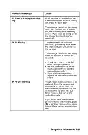
... be replaced. Open the top door and remove the photoconductor unit. If it does not: • Check the contacts on the PC drum cartridge connector. • Be sure connector CN6 on page 2-47. 84 PC Missing The photoconductor unit is closed . Install the new photoconductor unit ...door. Diagnostic Information 2-21 Close the back door. If you do not have a replacement photoconductor unit available, press Go to continue normal printer operations until you still have the problem, replace the mechanical controller board. 84 PC Life Warning The photoconductor unit needs to the "Sensor...
... be replaced. Open the top door and remove the photoconductor unit. If it does not: • Check the contacts on the PC drum cartridge connector. • Be sure connector CN6 on page 2-47. 84 PC Missing The photoconductor unit is closed . Install the new photoconductor unit ...door. Diagnostic Information 2-21 Close the back door. If you do not have a replacement photoconductor unit available, press Go to continue normal printer operations until you still have the problem, replace the mechanical controller board. 84 PC Life Warning The photoconductor unit needs to the "Sensor...
Service Manual
Page 61
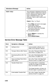
... 913 Symptom or Message Software Error Transport Motor (M2) Failure Developing Motor (M1) Failure Toner Cartridge Rack Motor (M3) Failure Transfer Roller Error Action Unrecoverable software error. Go to select print material from a missing tray. The printer clears the message and resumes printing. Refer to access the Busy menu. • Select Reset...
... 913 Symptom or Message Software Error Transport Motor (M2) Failure Developing Motor (M1) Failure Toner Cartridge Rack Motor (M3) Failure Transfer Roller Error Action Unrecoverable software error. Go to select print material from a missing tray. The printer clears the message and resumes printing. Refer to access the Busy menu. • Select Reset...
Service Manual
Page 64
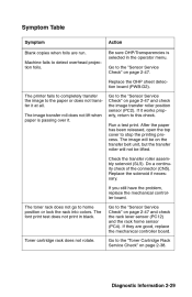
Go to home position or lock the rack into colors. Run a test print. If you still have the problem, replace the mechanical... does not print in the operator menu. Machine fails to the paper or does not transfer it . The printer fails to completely transfer the image to detect overhead projection foils. The image will be on page 2-47 and...page 2-38. Diagnostic Information 2-29 Do a continuity check of the connector (CN5). Replace the solenoid if necessary. Toner cartridge rack does not rotate. Go to the "Sensor Service Check" on the transfer belt unit, but the transfer roller ...
Go to home position or lock the rack into colors. Run a test print. If you still have the problem, replace the mechanical... does not print in the operator menu. Machine fails to the paper or does not transfer it . The printer fails to completely transfer the image to detect overhead projection foils. The image will be on page 2-47 and...page 2-38. Diagnostic Information 2-29 Do a continuity check of the connector (CN5). Replace the solenoid if necessary. Toner cartridge rack does not rotate. Go to the "Sensor Service Check" on the transfer belt unit, but the transfer roller ...
Service Manual
Page 73
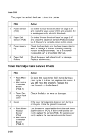
Jam 202 The paper has exited the fuser but not the printer. If it is working correctly, return to the "Sensor Service Check" on page 2-47 and check the fuser sensor (PC9) and actuator. This is not ... Action Go to check the rack home position sensor (PC4). Replace as necessary. 2 3 4 Paper Exit Rollers Toner Cartridge Rack Service Check FRU 1 • Rack Motor (M3) • Mechanical Controller Board (PWB-A) • Toner Cartridge Rack Latch Gears • Rack Home Position Sensor (PC4) • Mechanical Controller Board (PWB-A) Action Be sure the...
Jam 202 The paper has exited the fuser but not the printer. If it is working correctly, return to the "Sensor Service Check" on page 2-47 and check the fuser sensor (PC9) and actuator. This is not ... Action Go to check the rack home position sensor (PC4). Replace as necessary. 2 3 4 Paper Exit Rollers Toner Cartridge Rack Service Check FRU 1 • Rack Motor (M3) • Mechanical Controller Board (PWB-A) • Toner Cartridge Rack Latch Gears • Rack Home Position Sensor (PC4) • Mechanical Controller Board (PWB-A) Action Be sure the...
Service Manual
Page 100
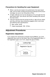
... tools around the printhead and the drum cartridge, be sure to turn the printer off your watch and ring, and wear laser protective goggles which must meet the following laser specifications: • Max. If the registration gap is brought into the laser beam path. Precautions for Handling the Laser Equipment • • • When a service job...
... tools around the printhead and the drum cartridge, be sure to turn the printer off your watch and ring, and wear laser protective goggles which must meet the following laser specifications: • Max. If the registration gap is brought into the laser beam path. Precautions for Handling the Laser Equipment • • • When a service job...
Service Manual
Page 102
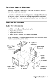
Repair Information 3-5 Open the Upper Unit. Remove each cover in the printer frame. Loosen the 3 rack solenoid mounting screws and adjust the solenoid up or down so there are 4.5 mm between the solenoid plunger and the solenoid ... rack lever solenoid. Rack Lever Solenoid Adjustment Make this adjustment whenever you reinstall the covers, be sure to insert the cover protrusions into the toner cartridge rack.
Repair Information 3-5 Open the Upper Unit. Remove each cover in the printer frame. Loosen the 3 rack solenoid mounting screws and adjust the solenoid up or down so there are 4.5 mm between the solenoid plunger and the solenoid ... rack lever solenoid. Rack Lever Solenoid Adjustment Make this adjustment whenever you reinstall the covers, be sure to insert the cover protrusions into the toner cartridge rack.
Service Manual
Page 104
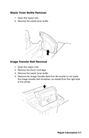
Open the Upper Unit. Open the Upper Unit. 2. Remove the Drum Cartridge. Remove the waste toner bottle. Remove the waste toner bottle. Be careful to not rotate the image transfer belt clockwise, as viewed from the right side of the printer. Waste Toner Bottle Removal 1. Repair Information 3-7 Image Transfer Belt Removal 1. 2. 3. 4. Remove the Image Transfer Belt Unit.
Open the Upper Unit. Open the Upper Unit. 2. Remove the Drum Cartridge. Remove the waste toner bottle. Remove the waste toner bottle. Be careful to not rotate the image transfer belt clockwise, as viewed from the right side of the printer. Waste Toner Bottle Removal 1. Repair Information 3-7 Image Transfer Belt Removal 1. 2. 3. 4. Remove the Image Transfer Belt Unit.
Service Manual
Page 127
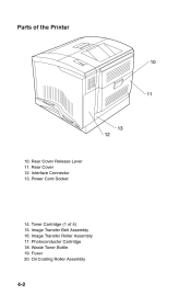
Parts of 4) 15. Interface Connector 13. Power Cord Socket 14. Photoconductor Cartridge 18. Waste Toner Bottle 19. Fuser 20. Image Transfer Roller Assembly 17. Oil Coating Roller Assembly 4-2 Rear Cover 12. Rear Cover Release Lever 11. Toner Cartridge (1 of the Printer 10. Image Transfer Belt Assembly 16.
Parts of 4) 15. Interface Connector 13. Power Cord Socket 14. Photoconductor Cartridge 18. Waste Toner Bottle 19. Fuser 20. Image Transfer Roller Assembly 17. Oil Coating Roller Assembly 4-2 Rear Cover 12. Rear Cover Release Lever 11. Toner Cartridge (1 of the Printer 10. Image Transfer Belt Assembly 16.
Service Manual
Page 132
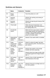
... bottle is at the home position. Switches and Sensors Name S1 S2 S3 S4 Power Switch Interlock Switch 1 Interlock Switch 2 Thermostat Connector Function Turns the printer on or off Detects the opening and closing of the rear cover. Detects the opening and closing of front cover. S5 P/H Shutter Switch S6 Waste... PC1 Detect if a sheet of paper has been fed to the fuser. Detects when the image transfer roller is installed. PC4 Detects if the toner cartridge rack is installed. When the front cover closes, it shuts down power to the...
... bottle is at the home position. Switches and Sensors Name S1 S2 S3 S4 Power Switch Interlock Switch 1 Interlock Switch 2 Thermostat Connector Function Turns the printer on or off Detects the opening and closing of the rear cover. Detects the opening and closing of front cover. S5 P/H Shutter Switch S6 Waste... PC1 Detect if a sheet of paper has been fed to the fuser. Detects when the image transfer roller is installed. PC4 Detects if the toner cartridge rack is installed. When the front cover closes, it shuts down power to the...
Service Manual
Page 208
...frames 2 assembly 5-10 fuser assembly 5-38 fuser removal 3-8 fuser service check 2-33 fuser/exit assembly 5-42 H handling laser equipment 3-3 handling PWBs with MOISICS 3-1 handling the drum cartridge 3-2 heater lamp removal 3-10 high voltage/sub high voltage board removal 3-12 housing assembly 5-2 how to use the ...parts catalog 5-1 B base sensor test 2-56 basic printer paper passage test 2-48 button test 2-51 C clean...
...frames 2 assembly 5-10 fuser assembly 5-38 fuser removal 3-8 fuser service check 2-33 fuser/exit assembly 5-42 H handling laser equipment 3-3 handling PWBs with MOISICS 3-1 handling the drum cartridge 3-2 heater lamp removal 3-10 high voltage/sub high voltage board removal 3-12 housing assembly 5-2 how to use the ...parts catalog 5-1 B base sensor test 2-56 basic printer paper passage test 2-48 button test 2-51 C clean...

Service Manual
Page 209
...2-39 printhead frame removal 3-15 printhead removal 3-11 printing process 4-6 service checks 2-33 service error message table 2-26 setting printer registration 2-50 setting the page count 2-58 shield plate removal 3-13 size sensing sensor test 2-55 start 2-1 status messages ...4-7 symptom table 2-29 synchronizing rollers 1-7 T third cassette assembly 5-54 toner cartridge rack removal 3-16 toner cartridge rack service check 2-38 toner empty/toner cartridge board removal 3-16 toner empty/toner cartridge detection 1-10 tools 1-1 transfer belt assembly 5-24 transfer roller assembly 5-28 transport...
...2-39 printhead frame removal 3-15 printhead removal 3-11 printing process 4-6 service checks 2-33 service error message table 2-26 setting printer registration 2-50 setting the page count 2-58 shield plate removal 3-13 size sensing sensor test 2-55 start 2-1 status messages ...4-7 symptom table 2-29 synchronizing rollers 1-7 T third cassette assembly 5-54 toner cartridge rack removal 3-16 toner cartridge rack service check 2-38 toner empty/toner cartridge board removal 3-16 toner empty/toner cartridge detection 1-10 tools 1-1 transfer belt assembly 5-24 transfer roller assembly 5-28 transport...


