Hardware Maintenance Manual
Page 5
... . 71 Removing the computer cover 72 Removing and reinstalling the front bezel . . . . 73 Installing or replacing a PCI card 74 Installing or replacing a memory module . . . . 77 Replacing the battery 79 Installing or replacing the optical drive . . . . . 80 Replacing the card reader 82 Replacing the...rear fan assembly 100 Completing the parts replacement 102 Chapter 10. General information . . . . 29 Lenovo ThinkVantage Tools 29 Lenovo Solution Center 29 SimpleTap 29 Lenovo Welcome 29 Additional information resources 30 Specifications 30 Chapter 4. Configuring RAID . . . . . 41 RAID...
... . 71 Removing the computer cover 72 Removing and reinstalling the front bezel . . . . 73 Installing or replacing a PCI card 74 Installing or replacing a memory module . . . . 77 Replacing the battery 79 Installing or replacing the optical drive . . . . . 80 Replacing the card reader 82 Replacing the...rear fan assembly 100 Completing the parts replacement 102 Chapter 10. General information . . . . 29 Lenovo ThinkVantage Tools 29 Lenovo Solution Center 29 SimpleTap 29 Lenovo Welcome 29 Additional information resources 30 Specifications 30 Chapter 4. Configuring RAID . . . . . 41 RAID...
Hardware Maintenance Manual
Page 50
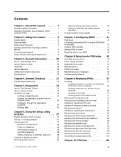
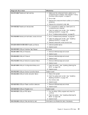
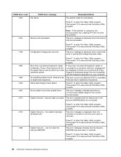
...review the log file. 2. System board 1. See "Updating (flashing) the BIOS" on page 169. 2. Flash the system. Flash the system. Run memory test 4. System board 1. See "Updating (flashing) the BIOS" on page 169. 2. Flash the system. See "Updating (flashing) the BIOS" ...system. System board 1. See "Updating (flashing) the BIOS" on page 169. 2. System board 1. Press F3 to reset the log file. 44 ThinkStation Hardware Maintenance Manual System board 1. See "Updating (flashing) the BIOS" on page 169. 2. See "Updating (flashing) the BIOS" on page 169...
...review the log file. 2. System board 1. See "Updating (flashing) the BIOS" on page 169. 2. Flash the system. Flash the system. Run memory test 4. System board 1. See "Updating (flashing) the BIOS" on page 169. 2. Flash the system. See "Updating (flashing) the BIOS" ...system. System board 1. See "Updating (flashing) the BIOS" on page 169. 2. System board 1. Press F3 to reset the log file. 44 ThinkStation Hardware Maintenance Manual System board 1. See "Updating (flashing) the BIOS" on page 169. 2. See "Updating (flashing) the BIOS" on page 169...
Hardware Maintenance Manual
Page 51
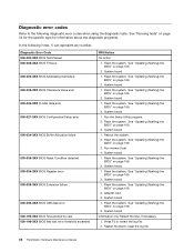
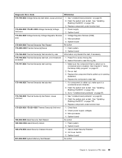
.... 3. See "Updating (flashing) the BIOS" on page 169. 2. See "Updating (flashing) the BIOS" on page 169. 2. See "Updating (flashing) the BIOS" on page 169. 3. Run memory test. 4. Replace the component that is called out is connected and/or enabled. Make sure the component that is called out is called out in...
.... 3. See "Updating (flashing) the BIOS" on page 169. 2. See "Updating (flashing) the BIOS" on page 169. 2. See "Updating (flashing) the BIOS" on page 169. 3. Run memory test. 4. Replace the component that is called out is connected and/or enabled. Make sure the component that is called out is called out in...
Hardware Maintenance Manual
Page 57
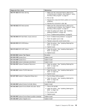
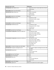
... 37. 2. Replace component under test. 1. External parallel device 2. Remove USB device(s) and re-test. 2. System board 1. See "Updating (flashing) the BIOS" on page 169. 2. Run memory test. 4. System board 1. Flash the system. Chapter 8. Re-run test. 3. See "Updating (flashing) the BIOS" on page 169. 3. System board System board 1. Symptom-to "Undetermined...
... 37. 2. Replace component under test. 1. External parallel device 2. Remove USB device(s) and re-test. 2. System board 1. See "Updating (flashing) the BIOS" on page 169. 2. Run memory test. 4. System board 1. Flash the system. Chapter 8. Re-run test. 3. See "Updating (flashing) the BIOS" on page 169. 3. System board System board 1. Symptom-to "Undetermined...
Hardware Maintenance Manual
Page 65
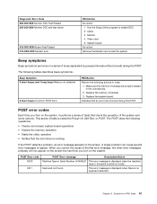
... Sensor(s) test failed, cause unknown 1. Go to -FRU Index 59 System board 185-278-XXX Asset Security Chassis Intrusion 1. System board 201-000-XXX System Memory Test Passed No action Chapter 8. System board 170-254-XXX Voltage Sensor(s) Voltage Regulator Module error 1. Flash system 2. If a component is called out, make sure...
... Sensor(s) test failed, cause unknown 1. Go to -FRU Index 59 System board 185-278-XXX Asset Security Chassis Intrusion 1. System board 201-000-XXX System Memory Test Passed No action Chapter 8. System board 170-254-XXX Voltage Sensor(s) Voltage Regulator Module error 1. Flash system 2. If a component is called out, make sure...
Hardware Maintenance Manual
Page 66
...1. Hard Disk Drive Cable 2. Check and test Keyboard. 3. System board No action Remove the Joystick and re-test the system. 60 ThinkStation Hardware Maintenance Manual CD-ROM drive 4. Reseat the hard disk drive cable 4. CD-ROM Drive Cable 2. Check power supply voltages 3. System... Diskette drive 4. Hard Disk Drive Cable 2. SCSI adapter card 6. System board No action 1. Keyboard 2. System board No action 1. Replace the memory module called out by the test. 2. Remove the Hi-Capacity Cartridge Drive and re-test the system. 1. Cache, if removable 2. Check power ...
...1. Hard Disk Drive Cable 2. Check and test Keyboard. 3. System board No action Remove the Joystick and re-test the system. 60 ThinkStation Hardware Maintenance Manual CD-ROM drive 4. Reseat the hard disk drive cable 4. CD-ROM Drive Cable 2. Check power supply voltages 3. System... Diskette drive 4. Hard Disk Drive Cable 2. SCSI adapter card 6. System board No action 1. Keyboard 2. System board No action 1. Replace the memory module called out by the test. 2. Remove the Hi-Capacity Cartridge Drive and re-test the system. 1. Cache, if removable 2. Check power ...
Hardware Maintenance Manual
Page 67
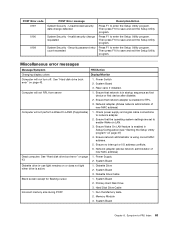
...the serial number is no keyboard detected. Symptom-to appear. The following tables describes beep symptoms. Beep Symptom 3 short beeps and 1 long beep Memory not detected 2 short beeps Common POST Error FRU/Action Perform the following operations. • Checks some options. A single problem can cause several ...250-XXX Monitor DDC self test failure 415-000-XXXModem Test Passed 415-XXX-XXX Modem error FRU/Action No action 1. Replace the memory module(s). 3. System board No action Remove the Modem and re-test the system. Keyboard not found This error message is displayed when...
...the serial number is no keyboard detected. Symptom-to appear. The following tables describes beep symptoms. Beep Symptom 3 short beeps and 1 long beep Memory not detected 2 short beeps Common POST Error FRU/Action Perform the following operations. • Checks some options. A single problem can cause several ...250-XXX Monitor DDC self test failure 415-000-XXXModem Test Passed 415-XXX-XXX Modem error FRU/Action No action 1. Replace the memory module(s). 3. System board No action Remove the Modem and re-test the system. Keyboard not found This error message is displayed when...
Hardware Maintenance Manual
Page 68
...Utility program. Then press F10 to enter the Setup Utility program. Then press F10 to save and exit the Setup Utility program. 62 ThinkStation Hardware Maintenance Manual This error message is caused by the microprocessor fan, pressing F10 will be displayed to inform you set up within ... the Setup Utility program. Power off and remove all of the fingerprint keyboards except the one external fingerprint reader is displayed when the memory size has decreased. 1762 Configuration change has been made. 1820 1962 0162 0167 0175 Press F1 to repeat boot sequence. This error ...
...Utility program. Then press F10 to enter the Setup Utility program. Then press F10 to save and exit the Setup Utility program. 62 ThinkStation Hardware Maintenance Manual This error message is caused by the microprocessor fan, pressing F10 will be displayed to inform you set up within ... the Setup Utility program. Power off and remove all of the fingerprint keyboards except the one external fingerprint reader is displayed when the memory size has decreased. 1762 Configuration change has been made. 1820 1962 0162 0167 0175 Press F1 to repeat boot sequence. This error ...
Hardware Maintenance Manual
Page 69
...card, if installed. Network adapter (Advise network administrator of new MAC address) Dead computer. Power Supply 2. Hard Disk Drive Cable Incorrect memory size during POST 1. Then press F10 to save and exit the Setup Utility program. Ensure that network is enabled for flashing cursor.... and signal cable connections to enter the Setup Utility program. Ensure no interrupt or I/O address conflicts. 6. System Board 3. Memory Module 3. Run the Memory tests. 2. Symptom-to enter the Setup Utility program. Then press F10 to enable Wake on page 37) 4. System Board...
...card, if installed. Network adapter (Advise network administrator of new MAC address) Dead computer. Power Supply 2. Hard Disk Drive Cable Incorrect memory size during POST 1. Then press F10 to save and exit the Setup Utility program. Ensure that network is enabled for flashing cursor.... and signal cable connections to enter the Setup Utility program. Ensure no interrupt or I/O address conflicts. 6. System Board 3. Memory Module 3. Run the Memory tests. 2. Symptom-to enter the Setup Utility program. Then press F10 to enable Wake on page 37) 4. System Board...
Hardware Maintenance Manual
Page 71
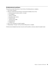
... Index 65 Turn off the computer. 2. External Cache f. If all devices and adapters have been removed, and the problem continues, replace the system board. Memory modules d. Extended video memory e. a. Hard disk drive h. Any adapters c. Turn on how to find the failing device or adapter. Undetermined problems This section provides instructions on the...
... Index 65 Turn off the computer. 2. External Cache f. If all devices and adapters have been removed, and the problem continues, replace the system board. Memory modules d. Extended video memory e. a. Hard disk drive h. Any adapters c. Turn on how to find the failing device or adapter. Undetermined problems This section provides instructions on the...
Hardware Maintenance Manual
Page 76
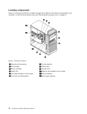
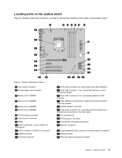
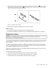
Figure 3. Locating components Figure 3 "Component locations" on page 72. Component locations 1 Heat sink and fan assembly 2 Microprocessor 3 Memory module(s) 4 Optical drive 5 Card reader (available in some models) 6 Front audio and USB assembly 7 Front fan assembly 8 System board 9 Hard disk drive 10 Graphics card (available in your computer. To remove the computer cover, see "Removing the computer cover" on page 70 shows the locations of the various components in some models) 11 Rear fan assembly 12 Power supply assembly 70 ThinkStation Hardware Maintenance Manual
Figure 3. Locating components Figure 3 "Component locations" on page 72. Component locations 1 Heat sink and fan assembly 2 Microprocessor 3 Memory module(s) 4 Optical drive 5 Card reader (available in some models) 6 Front audio and USB assembly 7 Front fan assembly 8 System board 9 Hard disk drive 10 Graphics card (available in your computer. To remove the computer cover, see "Removing the computer cover" on page 70 shows the locations of the various components in some models) 11 Rear fan assembly 12 Power supply assembly 70 ThinkStation Hardware Maintenance Manual
Hardware Maintenance Manual
Page 77
System board part locations 1 4-pin power connector 2 Microprocessor fan connector 3 Memory slot 1 (DIMM1) 4 Memory slot 2 (DIMM2) 5 Memory slot 3 (DIMM3) 6 Memory slot 4 (DIMM4) 7 Thermal sensor connector 8 24-pin power connector 9 Battery 10 SATA connectors 1 and 2 (SATA 3.0 connectors) 11 SATA connector 3 (SATA 2.0 connector) 12 eSATA connector 13 ...
System board part locations 1 4-pin power connector 2 Microprocessor fan connector 3 Memory slot 1 (DIMM1) 4 Memory slot 2 (DIMM2) 5 Memory slot 3 (DIMM3) 6 Memory slot 4 (DIMM4) 7 Thermal sensor connector 8 24-pin power connector 9 Battery 10 SATA connectors 1 and 2 (SATA 3.0 connectors) 11 SATA connector 3 (SATA 2.0 connector) 12 eSATA connector 13 ...
Hardware Maintenance Manual
Page 82
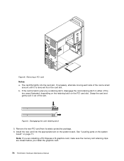
... PCI card from the card slot. Note: If you are installing a PCI Express x16 graphics card, make sure the memory slot retaining clips are closed before you install the graphics card. 76 ThinkStation Hardware Maintenance Manual The card fits tightly into the appropriate slot on the system board. b. Install the new card...
... PCI card from the card slot. Note: If you are installing a PCI Express x16 graphics card, make sure the memory slot retaining clips are closed before you install the graphics card. 76 ThinkStation Hardware Maintenance Manual The card fits tightly into the appropriate slot on the system board. b. Install the new card...
Hardware Maintenance Manual
Page 83
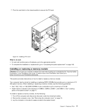
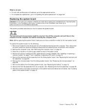
...sequence of the ThinkStation User Guide, go to secure the PCI card. Pivot the card latch to the closed position to "Completing the parts replacement" on page 102. Your computer has four slots for easier access to : http://www.lenovo.com/ThinkStationUserGuides. Remove the computer cover. Installing or replacing a memory module Attention: ... parts on the system board" on its side for installing or replacing DDR3 UDIMMs that provide up to a maximum of 16 GB. • Install memory modules in the ThinkStation User Guide. Replacing FRUs 77 Lay the computer on page 71. 7.
...sequence of the ThinkStation User Guide, go to secure the PCI card. Pivot the card latch to the closed position to "Completing the parts replacement" on page 102. Your computer has four slots for easier access to : http://www.lenovo.com/ThinkStationUserGuides. Remove the computer cover. Installing or replacing a memory module Attention: ... parts on the system board" on its side for installing or replacing DDR3 UDIMMs that provide up to a maximum of 16 GB. • Install memory modules in the ThinkStation User Guide. Replacing FRUs 77 Lay the computer on page 71. 7.
Hardware Maintenance Manual
Page 84
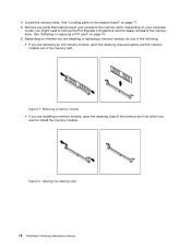
...you are installing or replacing a memory module, do one of the following: • If you are installing a memory module, open the retaining clips and gently pull the memory module out of the memory slot into which you want to the memory slots. Removing a memory module • If you might..." on page 74. 6. 4. Locate the memory slots. Figure 12. Remove any parts that might need to remove the PCI Express x16 graphics card for easier access to install the memory module. Figure 11. Opening the retaining clips 78 ThinkStation Hardware Maintenance Manual See "Installing or replacing ...
...you are installing or replacing a memory module, do one of the following: • If you are installing a memory module, open the retaining clips and gently pull the memory module out of the memory slot into which you want to the memory slots. Removing a memory module • If you might..." on page 74. 6. 4. Locate the memory slots. Figure 12. Remove any parts that might need to remove the PCI Express x16 graphics card for easier access to install the memory module. Figure 11. Opening the retaining clips 78 ThinkStation Hardware Maintenance Manual See "Installing or replacing ...
Hardware Maintenance Manual
Page 85
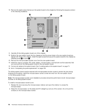
Figure 13. What to : http://www.lenovo.com/ThinkStationUserGuides. To obtain a copy of the battery. If ... replacing and disposing of the ThinkStation User Guide, go to the "Lithium battery notice" in the ThinkStation User Guide. Your computer has a special type of memory that the notch 1 on the memory module aligns correctly with another piece...open your computer or attempt any repair before reading and understanding the "Important safety information" in the ThinkStation Safety and Warranty Guide for built-in features, such as parallel-port assignments (configuration). A battery...
Figure 13. What to : http://www.lenovo.com/ThinkStationUserGuides. To obtain a copy of the battery. If ... replacing and disposing of the ThinkStation User Guide, go to the "Lithium battery notice" in the ThinkStation User Guide. Your computer has a special type of memory that the notch 1 on the memory module aligns correctly with another piece...open your computer or attempt any repair before reading and understanding the "Important safety information" in the ThinkStation Safety and Warranty Guide for built-in features, such as parallel-port assignments (configuration). A battery...
Hardware Maintenance Manual
Page 97
... from the computer. See "Installing or replacing a memory module" on page 77 and "Installing or replacing a PCI card" on how to let the computer cool before reading and understanding the "Important safety information" in the ThinkStation User Guide. CAUTION: The heat sink and microprocessor might...http://www.lenovo.com/ThinkStationUserGuides. To replace the system board, do next: • To work with another piece of all cable connections on the system board and disconnect all memory modules and PCI cards that are currently installed. To obtain a copy of the ThinkStation User Guide,...
... from the computer. See "Installing or replacing a memory module" on page 77 and "Installing or replacing a PCI card" on how to let the computer cool before reading and understanding the "Important safety information" in the ThinkStation User Guide. CAUTION: The heat sink and microprocessor might...http://www.lenovo.com/ThinkStationUserGuides. To replace the system board, do next: • To work with another piece of all cable connections on the system board and disconnect all memory modules and PCI cards that are currently installed. To obtain a copy of the ThinkStation User Guide,...
Hardware Maintenance Manual
Page 98
...in the new system board are aligned with microprocessor socket covers to the chassis by installing screw 8 to screw 1 . 13. Install the memory modules, PCI cards, battery, microprocessor, and heat sink and fan assembly that secure the system board to protect the pins during shipping and handling...lift it straight up and out of the chassis. 12. See "Locating parts on the system board" on the microprocessor socket. 92 ThinkStation Hardware Maintenance Manual Carefully lift the failing system board out of the socket. Release the lever securing the microprocessor retainer and open the ...
...in the new system board are aligned with microprocessor socket covers to the chassis by installing screw 8 to screw 1 . 13. Install the memory modules, PCI cards, battery, microprocessor, and heat sink and fan assembly that secure the system board to protect the pins during shipping and handling...lift it straight up and out of the chassis. 12. See "Locating parts on the system board" on the microprocessor socket. 92 ThinkStation Hardware Maintenance Manual Carefully lift the failing system board out of the socket. Release the lever securing the microprocessor retainer and open the ...
Hardware Maintenance Manual
Page 115
...7823: CTO • MT 7824: CTO 12J 17J 18J 34G 35G 44G 46G 55U 55F 65C 71M 85A 91J 95U 95F A4G D1G Memory module, 2GB ECC UDIMM (1333) • MT 7782: CTO • MT 7783: CTO 11J 12J 13J 14J 15J 25G 26G ... 81G 82A 83A 84A 85A 87A 88A 89J 91J 92J 93J A7G B6C B7C C2G B9J C8G C9G D1G D2G D3M D4M D5G Memory module, 4GB ECC UDIMM (1333) • MT 7782: CTO • MT 7783: CTO 23M 32U 32F 33U 33F 34U...; MT 7824: CTO 31M 56U 56F 57U 57F 59B 75S 75D 75Y 77S 77D 77Y 78S 78D 78Y 79S 79D 79Y A2G A3G Memory module, 2GB non-ECC UDIMM (1333) • MT 7782: CTO • MT 7783: CTO 16M 17M 19M 21M 22M 24M...
...7823: CTO • MT 7824: CTO 12J 17J 18J 34G 35G 44G 46G 55U 55F 65C 71M 85A 91J 95U 95F A4G D1G Memory module, 2GB ECC UDIMM (1333) • MT 7782: CTO • MT 7783: CTO 11J 12J 13J 14J 15J 25G 26G ... 81G 82A 83A 84A 85A 87A 88A 89J 91J 92J 93J A7G B6C B7C C2G B9J C8G C9G D1G D2G D3M D4M D5G Memory module, 4GB ECC UDIMM (1333) • MT 7782: CTO • MT 7783: CTO 23M 32U 32F 33U 33F 34U...; MT 7824: CTO 31M 56U 56F 57U 57F 59B 75S 75D 75Y 77S 77D 77Y 78S 78D 78Y 79S 79D 79Y A2G A3G Memory module, 2GB non-ECC UDIMM (1333) • MT 7782: CTO • MT 7783: CTO 16M 17M 19M 21M 22M 24M...

Hardware Maintenance Manual
Page 116
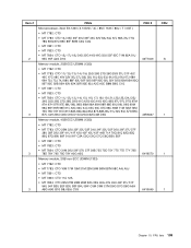
Item # 3 3 4 4 FRUs Memory module, 4GB non-ECC UDIMM (1333) • MT 7782: CTO • MT 7783: CTO 75Q 76Q 77Q 78Q 84Q 85Q A6A A7A A8A A9A B1A ... • MT 7823: CTO • MT 7824: CTO 52U 52F 53U 53F 54U 54F 55U 55F 95U 95F A4G A1G B5U B5F A6H C4U C4F Memory module, 8GB ECC UDIMM (1333) • MT 7782: CTO • MT 7783: CTO • MT 7821: CTO • MT 7823: CTO • MT 7824: CTO... C2G C3G C4U C4F C5M C6M C7M C8G C9G D1G D2G D3M D4M D5G D6G D7G D8G D9J FRU # 89Y9224 03T8429 71Y5543 71Y5545 CRU 1 1 1 1 110 ThinkStation Hardware Maintenance Manual
Item # 3 3 4 4 FRUs Memory module, 4GB non-ECC UDIMM (1333) • MT 7782: CTO • MT 7783: CTO 75Q 76Q 77Q 78Q 84Q 85Q A6A A7A A8A A9A B1A ... • MT 7823: CTO • MT 7824: CTO 52U 52F 53U 53F 54U 54F 55U 55F 95U 95F A4G A1G B5U B5F A6H C4U C4F Memory module, 8GB ECC UDIMM (1333) • MT 7782: CTO • MT 7783: CTO • MT 7821: CTO • MT 7823: CTO • MT 7824: CTO... C2G C3G C4U C4F C5M C6M C7M C8G C9G D1G D2G D3M D4M D5G D6G D7G D8G D9J FRU # 89Y9224 03T8429 71Y5543 71Y5545 CRU 1 1 1 1 110 ThinkStation Hardware Maintenance Manual


