
User Manual
Page 5
... troubleshooting 63 Diagnostic programs 64 Lenovo ThinkVantage Toolbox 64 Lenovo System Toolbox 64 PC-Doctor for Rescue and Recovery . . . . . 65 PC-Doctor for DOS 65 Cleaning the mouse 66 Optical mouse 66 Non-optical mouse 67 Chapter 8. Using the Setup Utility program 53 Starting the Setup Utility program 53 Viewing and changing settings 53 Using passwords 53 Password considerations 54 Power-On Password 54 Administrator Password 54 Hard Disk Password 54 Setting, changing, and deleting a password . . . 54 Enabling or disabling a device 55 Selecting a startup device...
... troubleshooting 63 Diagnostic programs 64 Lenovo ThinkVantage Toolbox 64 Lenovo System Toolbox 64 PC-Doctor for Rescue and Recovery . . . . . 65 PC-Doctor for DOS 65 Cleaning the mouse 66 Optical mouse 66 Non-optical mouse 67 Chapter 8. Using the Setup Utility program 53 Starting the Setup Utility program 53 Viewing and changing settings 53 Using passwords 53 Password considerations 54 Power-On Password 54 Administrator Password 54 Hard Disk Password 54 Setting, changing, and deleting a password . . . 54 Enabling or disabling a device 55 Selecting a startup device...
User Manual
Page 9
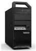
... by model type) Memory v Supports up to four DDR3 ECC UDIMMs (double data rate 3 error correction code unbuffered dual inline memory modules) or DDR3 Non-ECC UDIMMs Drives v Card reader (installed in some models) v Optical drive v Serial Advanced Technology Attachment (SATA) internal hard disk drive Video subsystem v Integrated graphics card for a VGA (Video Graphics Array) connector and a DisplayPort connector (not applicable on some models) v PCI (Peripheral Component Interconnect) Express x16 graphics card slot on the system board for a discrete graphics card Audio subsystem v Integrated...
... by model type) Memory v Supports up to four DDR3 ECC UDIMMs (double data rate 3 error correction code unbuffered dual inline memory modules) or DDR3 Non-ECC UDIMMs Drives v Card reader (installed in some models) v Optical drive v Serial Advanced Technology Attachment (SATA) internal hard disk drive Video subsystem v Integrated graphics card for a VGA (Video Graphics Array) connector and a DisplayPort connector (not applicable on some models) v PCI (Peripheral Component Interconnect) Express x16 graphics card slot on the system board for a discrete graphics card Audio subsystem v Integrated...

User Manual
Page 10
...not applicable on some models) v One VGA monitor connector (not applicable on some models) v Three audio connectors on the rear panel (audio line-in connector, audio line-out connector, and microphone connector) v Two audio connectors on the front panel (microphone connector and headphone connector) Expansion v One card reader bay v Two hard disk drive bays v Two optical drive bays v Two PCI card slots v One PCI Express x1 card slot v One PCI Express x16 graphics card slot Power supply v 280-watt auto-sensing power supply v Advanced Configuration and Power Interface (ACPI) support 2 User Guide
...not applicable on some models) v One VGA monitor connector (not applicable on some models) v Three audio connectors on the rear panel (audio line-in connector, audio line-out connector, and microphone connector) v Two audio connectors on the front panel (microphone connector and headphone connector) Expansion v One card reader bay v Two hard disk drive bays v Two optical drive bays v Two PCI card slots v One PCI Express x1 card slot v One PCI Express x16 graphics card slot Power supply v 280-watt auto-sensing power supply v Advanced Configuration and Power Interface (ACPI) support 2 User Guide

User Manual
Page 19
...SATA) optical drive in bay 1 v A 3.5-inch card reader in bay 3 (installed in some models) v A 3.5-inch SATA hard disk drive in bay 5 Chapter 1. Locating parts on the system board Figure 4 shows the locations of media. Figure 4. System board part locations 1 4-pin power connector 2 Microprocessor 3 Microprocessor fan connector 4 DIMM 2 5 DIMM 1 6 DIMM 4 7 DIMM 3 8 Thermal sensor connector 9 24-pin power connector 10 SATA connectors (3) 11 eSATA connector 12 Power fan connector 13 Front panel connector 14 Clear CMOS (Complementary Metal Oxide Semiconductor) /Recovery jumper 15 Front USB...
...SATA) optical drive in bay 1 v A 3.5-inch card reader in bay 3 (installed in some models) v A 3.5-inch SATA hard disk drive in bay 5 Chapter 1. Locating parts on the system board Figure 4 shows the locations of media. Figure 4. System board part locations 1 4-pin power connector 2 Microprocessor 3 Microprocessor fan connector 4 DIMM 2 5 DIMM 1 6 DIMM 4 7 DIMM 3 8 Thermal sensor connector 9 24-pin power connector 10 SATA connectors (3) 11 eSATA connector 12 Power fan connector 13 Front panel connector 14 Clear CMOS (Complementary Metal Oxide Semiconductor) /Recovery jumper 15 Front USB...

User Manual
Page 42
... the front fan assembly. Remove the computer cover. See "Locating parts on the system board" on the system board. Remove the front bezel. Note: If your computer. See "Replacing the secondary hard disk drive" on how to : http://www.lenovo.com/support This section provides instructions on page 29. 34 User Guide To obtain a copy of the ThinkStation Safety and Warranty Guide, go to replace the front fan assembly. See "Removing and...
... the front fan assembly. Remove the computer cover. See "Locating parts on the system board" on the system board. Remove the front bezel. Note: If your computer. See "Replacing the secondary hard disk drive" on how to : http://www.lenovo.com/support This section provides instructions on page 29. 34 User Guide To obtain a copy of the ThinkStation Safety and Warranty Guide, go to replace the front fan assembly. See "Removing and...
User Manual
Page 60
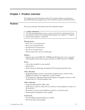
... install the device driver using rescue media" on page 50. Note: If you use an external device, you must first turn off your computer before connecting the external device. The TXT file contains information about how to the factory default settings. See "Creating and using the INF file, click Start → Help and Support to enter the Windows Help and Support information system for a SETUP.EXE file. v Use a recovery repair diskette to repair the Rescue and Recovery...
... install the device driver using rescue media" on page 50. Note: If you use an external device, you must first turn off your computer before connecting the external device. The TXT file contains information about how to the factory default settings. See "Creating and using the INF file, click Start → Help and Support to enter the Windows Help and Support information system for a SETUP.EXE file. v Use a recovery repair diskette to repair the Rescue and Recovery...
User Manual
Page 67
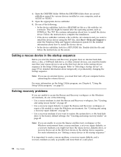
... computer hardware can easily update POST, BIOS, and the Setup Utility program by starting bootable CD/DVD image (known as downloadable files on page 56. 2. When prompted to change the machine type/model, press N. © Copyright Lenovo 2010 59 BIOS is a layer of software that translates instructions from other layers of software into electrical signals that is turned on your operating system. When prompted to change the serial number, press N. Type in the startup device sequence...
... computer hardware can easily update POST, BIOS, and the Setup Utility program by starting bootable CD/DVD image (known as downloadable files on page 56. 2. When prompted to change the machine type/model, press N. © Copyright Lenovo 2010 59 BIOS is a layer of software that translates instructions from other layers of software into electrical signals that is turned on your operating system. When prompted to change the serial number, press N. Type in the startup device sequence...

User Manual
Page 71
.... © Copyright Lenovo 2010 63 v No keys are set correctly. v The mouse is blank. v If your computer problem is turned on the computer. Troubleshooting and diagnostics This chapter describes some basic troubleshooting and diagnostic programs. If your computer has a secondary power switch on the rear of the computer is correctly connected to the monitor and to use the connector on . Symptom The computer does not start when you...
.... © Copyright Lenovo 2010 63 v No keys are set correctly. v The mouse is blank. v If your computer problem is turned on the computer. Troubleshooting and diagnostics This chapter describes some basic troubleshooting and diagnostic programs. If your computer has a secondary power switch on the rear of the computer is correctly connected to the monitor and to use the connector on . Symptom The computer does not start when you...
User Manual
Page 83
... and recovery operations 47 basic troubleshooting 63 BIOS, updating (flashing) 59, 60 boot-block recovery 60 C cable lock, security 42 changing password 54 startup device sequence 56 cleaning the mouse 66 CMOS, clearing 43 components, internal 10 computer cover removing 14 computer cover, reinstalling 40 connector 9 connectors front 7 rear 8 considerations, passwords 54 creating and using a recovery repair diskette 50 and using rescue media 49 creating and using recovery media 45 CRU completing the installation 40 customer support center 71 D deleting a password 54 Description 9 device drivers...
... and recovery operations 47 basic troubleshooting 63 BIOS, updating (flashing) 59, 60 boot-block recovery 60 C cable lock, security 42 changing password 54 startup device sequence 56 cleaning the mouse 66 CMOS, clearing 43 components, internal 10 computer cover removing 14 computer cover, reinstalling 40 connector 9 connectors front 7 rear 8 considerations, passwords 54 creating and using a recovery repair diskette 50 and using rescue media 49 creating and using recovery media 45 CRU completing the installation 40 customer support center 71 D deleting a password 54 Description 9 device drivers...
User Manual
Page 84
...Configuration and Power Interface (ACPI) support 2 features 2 76 User Guide power supply assembly, replacing 24 power-on self-test (POST) 59 Power-On, Password 54 programs, updating system 59 protection, password 43 purchasing additional services 72 R rear connectors 8 rear fan assembly, replacing 37 recovering from a POST/BIOS update failure 60 software 45 recovery boot-block 60 operations, backup and 47 problems, solving 52 recovery repair diskette, creating and using 50 recovery media, creating and using 45 reinstalling device drivers 51 removing computer cover 14 replacing hard disk drive...
...Configuration and Power Interface (ACPI) support 2 features 2 76 User Guide power supply assembly, replacing 24 power-on self-test (POST) 59 Power-On, Password 54 programs, updating system 59 protection, password 43 purchasing additional services 72 R rear connectors 8 rear fan assembly, replacing 37 recovering from a POST/BIOS update failure 60 software 45 recovery boot-block 60 operations, backup and 47 problems, solving 52 recovery repair diskette, creating and using 50 recovery media, creating and using 45 reinstalling device drivers 51 removing computer cover 14 replacing hard disk drive...

User Manual
Page 85
... 59 system board connectors 11 locating parts 11 locations 11 memory module 19 T television output notice 74 temporary startup device 55 trademarks 74 troubleshooting, basic 63 troubleshooting, diagnostics 63 U updating (flashing) BIOS 59 system programs 59 updating (flashing) BIOS 60 USB connector 9 using diagnostic programs 70 documentation 70 other services 71 passwords 53 recovery repair diskette, creating and using 50 rescue media, creating and 49 Setup Utility 53 V VGA monitor connector 9 video subsystem 1 viewing and changing settings 53 W warranty information 70 Web site, Lenovo 70...
... 59 system board connectors 11 locating parts 11 locations 11 memory module 19 T television output notice 74 temporary startup device 55 trademarks 74 troubleshooting, basic 63 troubleshooting, diagnostics 63 U updating (flashing) BIOS 59 system programs 59 updating (flashing) BIOS 60 USB connector 9 using diagnostic programs 70 documentation 70 other services 71 passwords 53 recovery repair diskette, creating and using 50 rescue media, creating and 49 Setup Utility 53 V VGA monitor connector 9 video subsystem 1 viewing and changing settings 53 W warranty information 70 Web site, Lenovo 70...
(English) Rescue and Recovery 4.3 Deployment Guide
Page 30
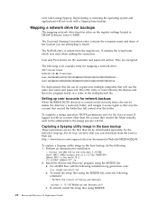
... To capture a Sysprep utility image in the rnrdeploy.xml file. To install the setup files using Sysprep. If logged in with a Sysprep base backup. To silently install the setup files using the MSIEXE file: a. Mapping a network drive for the User account. The following installation-log generation code: /L*v %temp%\rrinstall.txt b. Install the Rescue and Recovery program using MSIEXE: 22 Rescue and Recovery 4.3 Deployment Guide The Universal Naming Convention...
... To capture a Sysprep utility image in the rnrdeploy.xml file. To install the setup files using Sysprep. If logged in with a Sysprep base backup. To silently install the setup files using the MSIEXE file: a. Mapping a network drive for the User account. The following installation-log generation code: /L*v %temp%\rrinstall.txt b. Install the Rescue and Recovery program using MSIEXE: 22 Rescue and Recovery 4.3 Deployment Guide The Universal Naming Convention...
(English) Rescue and Recovery 4.3 Deployment Guide
Page 36
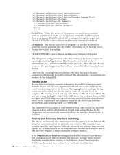
... software applications from tests performed by the Diagnostics tool are stored in a manner which can be easily found and accessible from the Rescue and Recovery environment, the end user is managed through the registry key settings: HKLM\SOFTWARE\Lenovo\Rescue and Recovery\Settings\OSAppsList The OSAppsList setting will see the simplified user interface each time the Rescue and Recovery program starts. The simplified user interface has a few basic options...
... software applications from tests performed by the Diagnostics tool are stored in a manner which can be easily found and accessible from the Rescue and Recovery environment, the end user is managed through the registry key settings: HKLM\SOFTWARE\Lenovo\Rescue and Recovery\Settings\OSAppsList The OSAppsList setting will see the simplified user interface each time the Rescue and Recovery program starts. The simplified user interface has a few basic options...

(English) Rescue and Recovery 4.5 Deployment Guide
Page 27
... Recovery.msi" /qn REBOOT="R" 5. Supported Sysprep multiple drive configurations Windows PE drive enumeration may be different than C:\ Primary, you want to Extended. Chapter 3. If you must set the registry entry to a partition other than the Windows main operating system enumeration for deployment. Shut down and reboot the machine when Sysprep is Complete will appear. 8. Install the Rescue and Recovery program using the power button. 10. Note: Backups will reboot...
... Recovery.msi" /qn REBOOT="R" 5. Supported Sysprep multiple drive configurations Windows PE drive enumeration may be different than C:\ Primary, you want to Extended. Chapter 3. If you must set the registry entry to a partition other than the Windows main operating system enumeration for deployment. Shut down and reboot the machine when Sysprep is Complete will appear. 8. Install the Rescue and Recovery program using the power button. 10. Note: Backups will reboot...
(English) Rescue and Recovery 4.5 Deployment Guide
Page 51
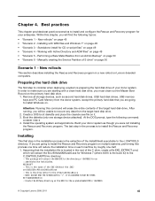
... /HDD=0 4. Preparing the hard disk drive The first step to install Windows on. Create a DOS boot diskette and place the cleandrv.exe file on page 49 • "Scenario 5 - If you are starting with Active Directory and ADM files" on it. 3. Working with a clean hard disk drive, you were not installing the Rescue and Recovery program. Build your donor system as second hard disk drives, USB hard disk drives, USB memory keys and PC Card Memory from...
... /HDD=0 4. Preparing the hard disk drive The first step to install Windows on. Create a DOS boot diskette and place the cleandrv.exe file on page 49 • "Scenario 5 - If you are starting with Active Directory and ADM files" on it. 3. Working with a clean hard disk drive, you were not installing the Rescue and Recovery program. Build your donor system as second hard disk drives, USB hard disk drives, USB memory keys and PC Card Memory from...

Hardware Maintenance Manual - ThinkStation E20
Page 37
... continue, replace the last device tested. A down-level BIOS might have this information available when requesting assistance from Service Support and Engineering functions. • Machine type and model • Processor or hard disk drive upgrades • Failure symptom - If you do receive the correct response, proceed to "Diagnostic error codes" on page 33. • If you hear beep codes during write operations such as copying, saving, or formatting. Power-on all display controls to...
... continue, replace the last device tested. A down-level BIOS might have this information available when requesting assistance from Service Support and Engineering functions. • Machine type and model • Processor or hard disk drive upgrades • Failure symptom - If you do receive the correct response, proceed to "Diagnostic error codes" on page 33. • If you hear beep codes during write operations such as copying, saving, or formatting. Power-on all display controls to...

Hardware Maintenance Manual - ThinkStation E20
Page 46
The Setup Utility program cannot be accessed until the valid password is typed in . When a Hard Disk Password is set, you are prompted to the External SATA connector cannot be accessed. Setting, changing, and deleting a password To set , you are set , change, or delete a password, do the following devices: Floppy Driver A USB Setup SATA Controller External SATA Port When this option is set , you can be any configuration settings. See "Starting the Setup Utility program" on page 39. To enable or disable a device, do the following: 1. For more information, see...
The Setup Utility program cannot be accessed until the valid password is typed in . When a Hard Disk Password is set, you are prompted to the External SATA connector cannot be accessed. Setting, changing, and deleting a password To set , you are set , change, or delete a password, do the following devices: Floppy Driver A USB Setup SATA Controller External SATA Port When this option is set , you can be any configuration settings. See "Starting the Setup Utility program" on page 39. To enable or disable a device, do the following: 1. For more information, see...

Hardware Maintenance Manual - ThinkStation E20
Page 71
...Miscellaneous error messages Message/Symptom FRU/Action Changing display colors Display/Monitor Computer will not RPL from server 1. Power Switch 2. Riser card, if installed. Ensure that the operating system settings are set to the computer. Network adapter (Advise network administrator of new MAC address) Dead computer. Ensure that network is active. Power Supply 2. System Board Diskette drive in-use light remains on or does not light when drive is in Setup/Configuration (see "Starting the Setup Utility program" on LAN. 3. Diskette Drive 2. Run the Memory tests...
...Miscellaneous error messages Message/Symptom FRU/Action Changing display colors Display/Monitor Computer will not RPL from server 1. Power Switch 2. Riser card, if installed. Ensure that the operating system settings are set to the computer. Network adapter (Advise network administrator of new MAC address) Dead computer. Ensure that network is active. Power Supply 2. System Board Diskette drive in-use light remains on or does not light when drive is in Setup/Configuration (see "Starting the Setup Utility program" on LAN. 3. Diskette Drive 2. Run the Memory tests...

Hardware Maintenance Manual - ThinkStation E20
Page 78
...) optical drive in bay 1 • A 3.5-inch card reader in bay 3 (installed in some models) • A 3.5-inch SATA hard disk drive in bay 5 72 Hardware Maintenance Manual System board part locations 1 4-pin power connector 2 Microprocessor 3 Microprocessor fan connector 4 DIMM 2 5 DIMM 1 6 DIMM 4 7 DIMM 3 8 Thermal sensor connector 9 24-pin power connector 10 SATA connectors (3) 11 eSATA connector 12 Power fan connector 13 Front panel connector 14 Clear CMOS (Complementary Metal Oxide Semiconductor) /Recovery jumper 15 Front USB connectors (2) 16 Front audio connector 17 Internal speaker...
...) optical drive in bay 1 • A 3.5-inch card reader in bay 3 (installed in some models) • A 3.5-inch SATA hard disk drive in bay 5 72 Hardware Maintenance Manual System board part locations 1 4-pin power connector 2 Microprocessor 3 Microprocessor fan connector 4 DIMM 2 5 DIMM 1 6 DIMM 4 7 DIMM 3 8 Thermal sensor connector 9 24-pin power connector 10 SATA connectors (3) 11 eSATA connector 12 Power fan connector 13 Front panel connector 14 Clear CMOS (Complementary Metal Oxide Semiconductor) /Recovery jumper 15 Front USB connectors (2) 16 Front audio connector 17 Internal speaker...

Hardware Maintenance Manual - ThinkStation E20
Page 173
... to access the Clear CMOS /Recovery jumper. You might need to remove the secondary hard disk drive to restart the operating system. See "Replacing the secondary hard disk drive" on the local area network (LAN). Reinstall the computer cover and reconnect the power cords for Advanced Power Management (APM) BIOS mode is completed, the series of the computer such as the system power supply, processor, hard disk drives, and some monitors. Turn on page 103. 9. Power management Power management reduces the power consumption of certain components of beeps...
... to access the Clear CMOS /Recovery jumper. You might need to remove the secondary hard disk drive to restart the operating system. See "Replacing the secondary hard disk drive" on the local area network (LAN). Reinstall the computer cover and reconnect the power cords for Advanced Power Management (APM) BIOS mode is completed, the series of the computer such as the system power supply, processor, hard disk drives, and some monitors. Turn on page 103. 9. Power management Power management reduces the power consumption of certain components of beeps...


