Hardware Maintenance Manual
Page 5
... 70 Locating components 71 Locating parts on the system board . . . . 71 Opening the computer cover 72 Removing and reinstalling the front bezel . . . . 73 Installing or replacing a memory module . . . . 74 Installing or replacing the PCI card 75 Replacing the ...diagnostic disc 38 Navigating through the diagnostics programs 38 Running tests 39 Viewing the test log 40 Chapter 6. FRU lists 99 © Copyright Lenovo 2011, 2012 iii Safety information 3 General safety 3 Electrical safety 3 Voltage-selection switch 5 Safety inspection guide 5 Handling electrostatic discharge-sensitive...
... 70 Locating components 71 Locating parts on the system board . . . . 71 Opening the computer cover 72 Removing and reinstalling the front bezel . . . . 73 Installing or replacing a memory module . . . . 74 Installing or replacing the PCI card 75 Replacing the ...diagnostic disc 38 Navigating through the diagnostics programs 38 Running tests 39 Viewing the test log 40 Chapter 6. FRU lists 99 © Copyright Lenovo 2011, 2012 iii Safety information 3 General safety 3 Electrical safety 3 Voltage-selection switch 5 Safety inspection guide 5 Handling electrostatic discharge-sensitive...
Hardware Maintenance Manual
Page 77
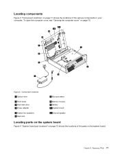
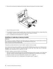
Component locations 1 Optical drive 2 Front bezel 3 Hard disk drive 4 Power adapter 5 System fan assembly 6 Heat sink 7 Microprocessor 8 Memory module 9 Battery 10 System board 11 Internal speaker Locating parts on the system board Figure 4 "System board part locations" on page 72 shows the locations of the various components in your computer. Locating components Figure 3 "Component locations" on page 71 shows the locations of the parts on the system board. To open the computer cover, see "Opening the computer cover" on page 72. Replacing FRUs 71 Chapter 8. Figure 3.
Component locations 1 Optical drive 2 Front bezel 3 Hard disk drive 4 Power adapter 5 System fan assembly 6 Heat sink 7 Microprocessor 8 Memory module 9 Battery 10 System board 11 Internal speaker Locating parts on the system board Figure 4 "System board part locations" on page 72 shows the locations of the various components in your computer. Locating components Figure 3 "Component locations" on page 71 shows the locations of the parts on the system board. To open the computer cover, see "Opening the computer cover" on page 72. Replacing FRUs 71 Chapter 8. Figure 3.

Hardware Maintenance Manual
Page 78
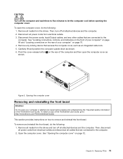
...for connecting USB ports 1 and 2 on the front bezel, LED indicators and power switch, and microphone and headphone connectors on how to : http://www.lenovo.com/ThinkCentreUserGuides This section provides instructions on the front bezel) 15 SATA connector 1 (SATA 3.0 connector) 16 System... fan connector 17 4-pin power connector 18 Microprocessor Opening the computer cover Attention: Do not open the computer cover. 72 ThinkCentre Hardware ...
...for connecting USB ports 1 and 2 on the front bezel, LED indicators and power switch, and microphone and headphone connectors on how to : http://www.lenovo.com/ThinkCentreUserGuides This section provides instructions on the front bezel) 15 SATA connector 1 (SATA 3.0 connector) 16 System... fan connector 17 4-pin power connector 18 Microprocessor Opening the computer cover Attention: Do not open the computer cover. 72 ThinkCentre Hardware ...
Hardware Maintenance Manual
Page 79
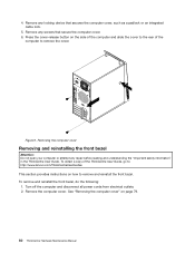
...as shown. Opening the computer cover Removing and reinstalling the front bezel Attention: Do not open your computer" on page 70. 4. To obtain a copy of the ThinkCentre User Guide, go to: http://www.lenovo.com/ThinkCentreUserGuides This section provides instructions on the rear of the... to five minutes to let the computer cool before reading and understanding the "Important safety information" in the ThinkCentre User Guide. To remove and reinstall the front bezel, do the following : 1. Remove all media from electrical outlets and disconnect all media from electrical outlets. ...
...as shown. Opening the computer cover Removing and reinstalling the front bezel Attention: Do not open your computer" on page 70. 4. To obtain a copy of the ThinkCentre User Guide, go to: http://www.lenovo.com/ThinkCentreUserGuides This section provides instructions on the rear of the... to five minutes to let the computer cool before reading and understanding the "Important safety information" in the ThinkCentre User Guide. To remove and reinstall the front bezel, do the following : 1. Remove all media from electrical outlets and disconnect all media from electrical outlets. ...
Hardware Maintenance Manual
Page 80
... open your computer or attempt any combination up to : http://www.lenovo.com/ThinkCentreUserGuides This section provides instructions on page 71. 74 ThinkCentre Hardware Maintenance Manual To obtain a copy of the bezel with the corresponding holes in the ThinkCentre User Guide. 3. Remove the front bezel by releasing the two plastic tabs and pivoting the front...
... open your computer or attempt any combination up to : http://www.lenovo.com/ThinkCentreUserGuides This section provides instructions on page 71. 74 ThinkCentre Hardware Maintenance Manual To obtain a copy of the bezel with the corresponding holes in the ThinkCentre User Guide. 3. Remove the front bezel by releasing the two plastic tabs and pivoting the front...
Hardware Maintenance Manual
Page 84
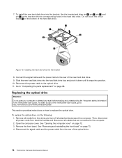
...parts replacement" on the bracket with the corresponding holes in the ThinkCentre User Guide. To replace the optical drive, do the following: 1. Connect the signal cable and the power cable to : http://www.lenovo.com/ThinkCentreUserGuides This section provides instructions on the bottom of the ..." in the hard disk drive. See "Removing and reinstalling the front bezel" on page 72. 3. 7. To obtain a copy of the ThinkCentre User Guide, go to the rear of the optical drive. 78 ThinkCentre Hardware Maintenance Manual Disconnect the signal cable and the power cable from the...
...parts replacement" on the bracket with the corresponding holes in the ThinkCentre User Guide. To replace the optical drive, do the following: 1. Connect the signal cable and the power cable to : http://www.lenovo.com/ThinkCentreUserGuides This section provides instructions on the bottom of the ..." in the hard disk drive. See "Removing and reinstalling the front bezel" on page 72. 3. 7. To obtain a copy of the ThinkCentre User Guide, go to the rear of the optical drive. 78 ThinkCentre Hardware Maintenance Manual Disconnect the signal cable and the power cable from the...
Hardware Maintenance Manual
Page 85
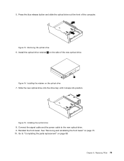
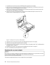
... the front of the new optical drive. Figure 13. Installing the optical drive 8. Install the optical drive retainer 1 on page 98. Reinstall the front bezel. Removing the optical drive 6. Slide the new optical drive into the drive bay until it snaps into position. Go to the new optical drive. 9. ...signal cable and the power cable to "Completing the parts replacement" on the side of the computer. Chapter 8. See "Removing and reinstalling the front bezel" on the optical drive 7. Figure 15. 5. Figure 14. Installing the retainer on page 73. 10. Replacing FRUs 79
... the front of the new optical drive. Figure 13. Installing the optical drive 8. Install the optical drive retainer 1 on page 98. Reinstall the front bezel. Removing the optical drive 6. Slide the new optical drive into the drive bay until it snaps into position. Go to the new optical drive. 9. ...signal cable and the power cable to "Completing the parts replacement" on the side of the computer. Chapter 8. See "Removing and reinstalling the front bezel" on the optical drive 7. Figure 15. 5. Figure 14. Installing the retainer on page 73. 10. Replacing FRUs 79
Hardware Maintenance Manual
Page 98
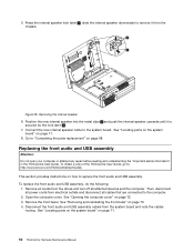
...replace the front audio and USB assembly. Open the computer cover. Remove the front bezel. Connect the new internal speaker cable to "Completing the parts replacement" on page 71. 92 ThinkCentre Hardware Maintenance Manual Remove all media from the chassis. Then, disconnect all power cords ...from the system board and note the cables routing. See "Opening the computer cover" on how to : http://www.lenovo.com/ThinkCentreUserGuides This section provides ...
...replace the front audio and USB assembly. Open the computer cover. Remove the front bezel. Connect the new internal speaker cable to "Completing the parts replacement" on page 71. 92 ThinkCentre Hardware Maintenance Manual Remove all media from the chassis. Then, disconnect all power cords ...from the system board and note the cables routing. See "Opening the computer cover" on how to : http://www.lenovo.com/ThinkCentreUserGuides This section provides ...
Hardware Maintenance Manual
Page 100
... and understanding the "Important safety information" in the chassis. Installing the front audio and USB assembly 11. Reinstall the front bezel. Go to : http://www.lenovo.com/ThinkCentreUserGuides This section provides instructions on page 73. 15. Install the screw to secure the front audio and USB assembly ...the chassis and align the screw hole in the bracket with the corresponding hole in the ThinkCentre User Guide. See "Locating parts on the system board" on page 98. To obtain a copy of the ThinkCentre User Guide, go to "Completing the parts replacement" on page 71. 14. 7. ...
... and understanding the "Important safety information" in the chassis. Installing the front audio and USB assembly 11. Reinstall the front bezel. Go to : http://www.lenovo.com/ThinkCentreUserGuides This section provides instructions on page 73. 15. Install the screw to secure the front audio and USB assembly ...the chassis and align the screw hole in the bracket with the corresponding hole in the ThinkCentre User Guide. See "Locating parts on the system board" on page 98. To obtain a copy of the ThinkCentre User Guide, go to "Completing the parts replacement" on page 71. 14. 7. ...
Hardware Maintenance Manual
Page 104
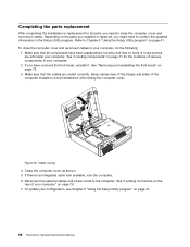
... update your computer, do the following: 1. See "Locating components" on page 71 for all components have removed the front bezel, reinstall it. See "Removing and reinstalling the front bezel" on page 41. 98 ThinkCentre Hardware Maintenance Manual Refer to the computer. If you have been reassembled correctly and that all parts, you might...
... update your computer, do the following: 1. See "Locating components" on page 71 for all components have removed the front bezel, reinstall it. See "Removing and reinstalling the front bezel" on page 41. 98 ThinkCentre Hardware Maintenance Manual Refer to the computer. If you have been reassembled correctly and that all parts, you might...
Hardware Maintenance Manual
Page 119
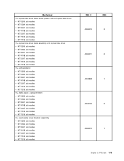
...modles • MT 5067: all modles • MT 7516: all modles • MT 7519: all modles Fru, SATA cable - Mechanical Fru, optical disk driver blank bezel, plastic, without optical disk driver • MT 0266: all modles • MT 0384: all modles • MT 2491: all modles • MT 4168: all modles... • MT 5067: all modles • MT 7516: all modles • MT 7519: all modles Fru, optical disk driver bezel assembly with optical disk driver • MT 0266: all modles • MT 0384: all modles • MT 2491: all modles • MT 4168: all modles...
...modles • MT 5067: all modles • MT 7516: all modles • MT 7519: all modles Fru, SATA cable - Mechanical Fru, optical disk driver blank bezel, plastic, without optical disk driver • MT 0266: all modles • MT 0384: all modles • MT 2491: all modles • MT 4168: all modles... • MT 5067: all modles • MT 7516: all modles • MT 7519: all modles Fru, optical disk driver bezel assembly with optical disk driver • MT 0266: all modles • MT 0384: all modles • MT 2491: all modles • MT 4168: all modles...
Hardware Maintenance Manual
Page 120
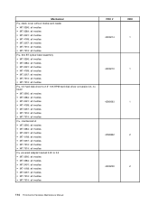
...modles • MT 5067: all modles • MT 7516: all modles • MT 7519: all modles Fru, 504 BT optical bezel assembly • MT 0266: all modles • MT 0384: all modles • MT 2491: all modles • MT 4168:...: all modles • MT 7519: all modles Fru, 3.5 hard disk driver to 2.5" 10K RPM hard disk driver conversion kit, no bezel • MT 0266: all modles • MT 0384: all modles • MT 2491: all modles • MT 4168: all...all modles • MT 7519: all modles FRU # 45K6214 45K6210 43N9593 43N9852 45K6209 CRU 1 1 1 2 2 114 ThinkCentre Hardware Maintenance Manual
...modles • MT 5067: all modles • MT 7516: all modles • MT 7519: all modles Fru, 504 BT optical bezel assembly • MT 0266: all modles • MT 0384: all modles • MT 2491: all modles • MT 4168:...: all modles • MT 7519: all modles Fru, 3.5 hard disk driver to 2.5" 10K RPM hard disk driver conversion kit, no bezel • MT 0266: all modles • MT 0384: all modles • MT 2491: all modles • MT 4168: all...all modles • MT 7519: all modles FRU # 45K6214 45K6210 43N9593 43N9852 45K6209 CRU 1 1 1 2 2 114 ThinkCentre Hardware Maintenance Manual
Hardware Maintenance Manual
Page 5
...Handling static-sensitive devices 78 Installing or replacing hardware 79 Removing the computer cover 79 Removing and reinstalling the front bezel . . 80 Installing or replacing a PCI card 81 Installing or replacing a memory module . . . 84 Installing or replacing... (multi-lingual translations) . . . . . 6 Chapter 3. General information . . . . 33 Lenovo Welcome 33 Lenovo ThinkVantage Tools 33 Lenovo Solution Center 33 SimpleTap 33 Lenovo ThinkVantage Toolbox 33 ThinkVantage Productivity Center 34 Additional information resources 34 Specifications 34 For machine types: 4468, 4473,...
...Handling static-sensitive devices 78 Installing or replacing hardware 79 Removing the computer cover 79 Removing and reinstalling the front bezel . . 80 Installing or replacing a PCI card 81 Installing or replacing a memory module . . . 84 Installing or replacing... (multi-lingual translations) . . . . . 6 Chapter 3. General information . . . . 33 Lenovo Welcome 33 Lenovo ThinkVantage Tools 33 Lenovo Solution Center 33 SimpleTap 33 Lenovo ThinkVantage Toolbox 33 ThinkVantage Productivity Center 34 Additional information resources 34 Specifications 34 For machine types: 4468, 4473,...
Hardware Maintenance Manual
Page 6
...Locating connectors, controls, and indicators on the front of your computer 116 Locating connectors on the rear of your operating system 476 iv ThinkCentre Hardware Maintenance Manual FRU lists 163 Overall: MT 4468, 4473, 4476, 4479, 4495, 4497, 4499, 4504, 4513, 4517, ...119 Locating internal drives 120 Handling static-sensitive devices 120 Installing or replacing hardware 121 Opening the computer cover 121 Removing and reinstalling the front bezel . . 122 Accessing the system board components and drives 124 Installing or replacing a memory module . . . 125 Installing or replacing ...
...Locating connectors, controls, and indicators on the front of your computer 116 Locating connectors on the rear of your operating system 476 iv ThinkCentre Hardware Maintenance Manual FRU lists 163 Overall: MT 4468, 4473, 4476, 4479, 4495, 4497, 4499, 4504, 4513, 4517, ...119 Locating internal drives 120 Handling static-sensitive devices 120 Installing or replacing hardware 121 Opening the computer cover 121 Removing and reinstalling the front bezel . . 122 Accessing the system board components and drives 124 Installing or replacing a memory module . . . 125 Installing or replacing ...
Hardware Maintenance Manual
Page 85
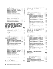
Figure 4. Locating parts on the system board Figure 4 "System board parts locations" on page 77 shows the locations of the parts on the front bezel) 5 Memory slot 2 (DIMM2) 19 Front USB connector 2 (for connecting USB port 1and 2 on the system board. System board parts locations 1 4-pin power connector 15 eSATA ...
Figure 4. Locating parts on the system board Figure 4 "System board parts locations" on page 77 shows the locations of the parts on the front bezel) 5 Memory slot 2 (DIMM2) 19 Front USB connector 2 (for connecting USB port 1and 2 on the system board. System board parts locations 1 4-pin power connector 15 eSATA ...
Hardware Maintenance Manual
Page 88
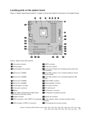
...See "Removing the computer cover" on the side of the computer and slide the cover to the rear of the ThinkCentre User Guide, go to: http://www.lenovo.com/ThinkCentreUserGuides This section provides instructions on how to remove the cover. Removing the computer cover Removing and reinstalling the ... the computer cover, such as a padlock or an integrated cable lock. 5. To remove and reinstall the front bezel, do the following: 1. Press the cover-release button on page 79. 80 ThinkCentre Hardware Maintenance Manual To obtain a copy of the computer to remove and reinstall the front...
...See "Removing the computer cover" on the side of the computer and slide the cover to the rear of the ThinkCentre User Guide, go to: http://www.lenovo.com/ThinkCentreUserGuides This section provides instructions on how to remove the cover. Removing the computer cover Removing and reinstalling the ... the computer cover, such as a padlock or an integrated cable lock. 5. To remove and reinstall the front bezel, do the following: 1. Press the cover-release button on page 79. 80 ThinkCentre Hardware Maintenance Manual To obtain a copy of the computer to remove and reinstall the front...
Hardware Maintenance Manual
Page 89
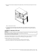
...information" in the chassis, then pivot the front bezel inwards until it snaps into position on how to : http://www.lenovo.com/ThinkCentreUserGuides This section provides instructions on the left side and pivoting the front bezel outward. Your computer has two standard PCI card slots... cover. To install or replace a PCI card, do the following: 1. Chapter 8. To obtain a copy of the front bezel with the corresponding holes in the ThinkCentre User Guide. Turn off the computer and disconnect all power cords from electrical outlets. 2. Figure 7. See "Removing the computer ...
...information" in the chassis, then pivot the front bezel inwards until it snaps into position on how to : http://www.lenovo.com/ThinkCentreUserGuides This section provides instructions on the left side and pivoting the front bezel outward. Your computer has two standard PCI card slots... cover. To install or replace a PCI card, do the following: 1. Chapter 8. To obtain a copy of the front bezel with the corresponding holes in the ThinkCentre User Guide. Turn off the computer and disconnect all power cords from electrical outlets. 2. Figure 7. See "Removing the computer ...
Hardware Maintenance Manual
Page 94
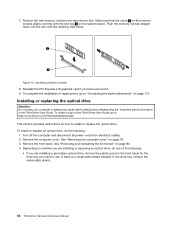
... the installation or replacement, go to: http://www.lenovo.com/ThinkCentreUserGuides This section provides instructions on page 79. 3. To install or replace an optical drive, do one of the ThinkCentre User Guide, go to use. Remove the front bezel. Remove the computer cover. Depending on whether you ...are installing a secondary optical drive, remove the plastic panel in the front bezel for the drive bay you want to "Completing ...
... the installation or replacement, go to: http://www.lenovo.com/ThinkCentreUserGuides This section provides instructions on page 79. 3. To install or replace an optical drive, do one of the ThinkCentre User Guide, go to use. Remove the front bezel. Remove the computer cover. Depending on whether you ...are installing a secondary optical drive, remove the plastic panel in the front bezel for the drive bay you want to "Completing ...
Hardware Maintenance Manual
Page 96
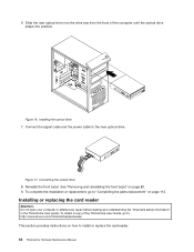
...the front bezel" on how to : http://www.lenovo.com/ThinkCentreUserGuides This section provides instructions on page 80. 9. Installing or replacing the card reader Attention: Do not open your computer or attempt any repair before reading and understanding the "Important safety information" in the ThinkCentre User Guide...Connecting the optical drive 8. To complete the installation or replacement, go to install or replace the card reader. 88 ThinkCentre Hardware Maintenance Manual To obtain a copy of the computer until the optical drive snaps into the drive bay from the front of ...
...the front bezel" on how to : http://www.lenovo.com/ThinkCentreUserGuides This section provides instructions on page 80. 9. Installing or replacing the card reader Attention: Do not open your computer or attempt any repair before reading and understanding the "Important safety information" in the ThinkCentre User Guide...Connecting the optical drive 8. To complete the installation or replacement, go to install or replace the card reader. 88 ThinkCentre Hardware Maintenance Manual To obtain a copy of the computer until the optical drive snaps into the drive bay from the front of ...
Hardware Maintenance Manual
Page 97
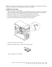
...card reader is only available in some models. Remove all media from electrical outlets and disconnect all attached devices and the computer. Remove the front bezel. Pivot the card reader retainer to the computer. 2. Removing the card reader retainer 6. Installing the card reader To install the card reader, ... turn off all cables that are connected to the left and slide it out of the new card reader. See "Removing and reinstalling the front bezel" on page 89. Replacing FRUs (Machine Types: 4468, 4473, 4476, 4479, 4495, 4497, 4499, 4504, 4513, 4517, 4524, 7021, 7032, 7034, 7049, ...
...card reader is only available in some models. Remove all media from electrical outlets and disconnect all attached devices and the computer. Remove the front bezel. Pivot the card reader retainer to the computer. 2. Removing the card reader retainer 6. Installing the card reader To install the card reader, ... turn off all cables that are connected to the left and slide it out of the new card reader. See "Removing and reinstalling the front bezel" on page 89. Replacing FRUs (Machine Types: 4468, 4473, 4476, 4479, 4495, 4497, 4499, 4504, 4513, 4517, 4524, 7021, 7032, 7034, 7049, ...
