Hardware Maintenance Manual
Page 10
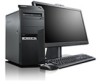
...• If an electrical accident occurs: - such touching can then operate the switch or unplug the power cord quickly. • Do not work alone under hazardous conditions or near power supplies - Use caution; do not become a victim yourself. - Some hand tools have , near you may...electrostatic discharges. If an electrical accident occurs, you when working with the reflective surface of mat to get medical aid. 4 ThinkCentre Hardware Maintenance Manual When using testers, set the controls correctly and use this type of a plastic dental mirror. Send another ...
...• If an electrical accident occurs: - such touching can then operate the switch or unplug the power cord quickly. • Do not work alone under hazardous conditions or near power supplies - Use caution; do not become a victim yourself. - Some hand tools have , near you may...electrostatic discharges. If an electrical accident occurs, you when working with the reflective surface of mat to get medical aid. 4 ThinkCentre Hardware Maintenance Manual When using testers, set the controls correctly and use this type of a plastic dental mirror. Send another ...

Hardware Maintenance Manual
Page 12
... • Arabic • Brazilian/Portuguese • Chinese (simplified) • Chinese (traditional) 6 ThinkCentre Hardware Maintenance Manual Handling electrostatic discharge-sensitive devices Any computer part containing transistors or integrated circuits (ICs) should be verified by equalizing the charge so that the power-supply cover fasteners (screws or rivets) have been certified (ISO 9000) as metal...
... • Arabic • Brazilian/Portuguese • Chinese (simplified) • Chinese (traditional) 6 ThinkCentre Hardware Maintenance Manual Handling electrostatic discharge-sensitive devices Any computer part containing transistors or integrated circuits (ICs) should be verified by equalizing the charge so that the power-supply cover fasteners (screws or rivets) have been certified (ISO 9000) as metal...
Hardware Maintenance Manual
Page 14
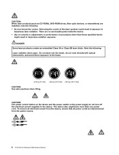
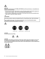
... practices when lifting. To remove all electrical current from the device, ensure that all power cords are disconnected from the power source. 2 1 8 ThinkCentre Hardware Maintenance Manual The device also might have more than those specified herein might result in... exposure to the device. DANGER Some laser products contain an embedded Class 3A or Class 3B laser diode. Do not stare into the beam, do not turn off the electrical current supplied...
... practices when lifting. To remove all electrical current from the device, ensure that all power cords are disconnected from the power source. 2 1 8 ThinkCentre Hardware Maintenance Manual The device also might have more than those specified herein might result in... exposure to the device. DANGER Some laser products contain an embedded Class 3A or Class 3B laser diode. Do not stare into the beam, do not turn off the electrical current supplied...

Hardware Maintenance Manual
Page 61
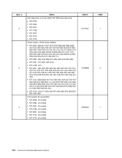
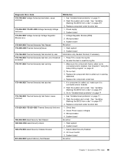
... the test, if necessary. 1. Replace the component under function test. 1. System board No action 1. Press F3 to -FRU index 55 IDE device 5. PCI card 2. Check power supply voltages 3.
... the test, if necessary. 1. Replace the component under function test. 1. System board No action 1. Press F3 to -FRU index 55 IDE device 5. PCI card 2. Check power supply voltages 3.

Hardware Maintenance Manual
Page 71
...power supply and signal cable connections to -FRU index 65 System Board Diskette drive in-use light remains on or does not light when drive is using correct MAC address. 5. Primary Hard Disk Drive 3. See "Power problems" on page 33. 1. Riser card, if installed Computer will not power... Ensure that network adapter is attached. Press any key to a computer, this error message will not perform a Wake on LAN. 3. Power Switch 2. Hard Disk Drive Cable Chapter 7. Ensure that network is completed. Press any key to remove all but the reader that the ...
...power supply and signal cable connections to -FRU index 65 System Board Diskette drive in-use light remains on or does not light when drive is using correct MAC address. 5. Primary Hard Disk Drive 3. See "Power problems" on page 33. 1. Riser card, if installed Computer will not power... Ensure that network adapter is attached. Press any key to a computer, this error message will not perform a Wake on LAN. 3. Power Switch 2. Hard Disk Drive Cable Chapter 7. Ensure that network is completed. Press any key to remove all but the reader that the ...
Hardware Maintenance Manual
Page 110
... hard disk drive • MT 0266: • MT 0384: • MT 2491: • MT 4168: • MT 5067: • MT 7516: • MT 7519: Power supply, 150W power adapter • MT 0266: B6M B7U B7F B7S B7M B8U B8F B8S B8M A1H A1V A2H A2V A3A A3T A4A A4T B4S B4D B4Y B5S...; MT 4168: all modles • MT 5067: all modles • MT 7516: all modles • MT 7519: all modles FRU # 91Y1657 54Y8838 03T9542 CRU 1 2 1 104 ThinkCentre Hardware Maintenance Manual
... hard disk drive • MT 0266: • MT 0384: • MT 2491: • MT 4168: • MT 5067: • MT 7516: • MT 7519: Power supply, 150W power adapter • MT 0266: B6M B7U B7F B7S B7M B8U B8F B8S B8M A1H A1V A2H A2V A3A A3T A4A A4T B4S B4D B4Y B5S...; MT 4168: all modles • MT 5067: all modles • MT 7516: all modles • MT 7519: all modles FRU # 91Y1657 54Y8838 03T9542 CRU 1 2 1 104 ThinkCentre Hardware Maintenance Manual
Hardware Maintenance Manual
Page 193
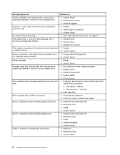
... is allowed to control the power management features of beeps. 9. Move the jumper from a POST/BIOS update failure If the power to your computer is interrupted while the POST and BIOS is completed, the series of the computer such as the system power supply, processor, hard disk drives,... and some monitors. Automatic configuration and power interface (ACPI) BIOS Being an ACPI BIOS system, the operating system is commonly called Boot-block Recovery...
... is allowed to control the power management features of beeps. 9. Move the jumper from a POST/BIOS update failure If the power to your computer is interrupted while the POST and BIOS is completed, the series of the computer such as the system power supply, processor, hard disk drives,... and some monitors. Automatic configuration and power interface (ACPI) BIOS Being an ACPI BIOS system, the operating system is commonly called Boot-block Recovery...
Hardware Maintenance Manual
Page 5
...46 Exiting the Setup Utility program 47 Chapter 7. General information . . . . 33 Lenovo Welcome 33 Lenovo ThinkVantage Tools 33 Lenovo Solution Center 33 SimpleTap 33 Lenovo ThinkVantage Toolbox 33 ThinkVantage Productivity Center 34 Additional information resources 34 Specifications 34 For machine types... translations) . . . . . 6 Chapter 3. Symptom-to-FRU index . . 49 Hard disk drive boot error 49 Power Supply Problems 49 Diagnostic error codes 49 Beep symptoms 67 POST error codes 68 Miscellaneous error messages 69 Undetermined problems 71 Chapter 8. Contents Chapter 1.
...46 Exiting the Setup Utility program 47 Chapter 7. General information . . . . 33 Lenovo Welcome 33 Lenovo ThinkVantage Tools 33 Lenovo Solution Center 33 SimpleTap 33 Lenovo ThinkVantage Toolbox 33 ThinkVantage Productivity Center 34 Additional information resources 34 Specifications 34 For machine types... translations) . . . . . 6 Chapter 3. Symptom-to-FRU index . . 49 Hard disk drive boot error 49 Power Supply Problems 49 Diagnostic error codes 49 Beep symptoms 67 POST error codes 68 Miscellaneous error messages 69 Undetermined problems 71 Chapter 8. Contents Chapter 1.
Hardware Maintenance Manual
Page 6
...battery 133 Replacing the hard disk drive 134 Replacing the optical drive 137 Replacing the heat sink and fan assembly . . 139 Replacing the power supply assembly . . . 142 Replacing the microprocessor 147 Replacing the system board 150 Replacing the system fan assembly . . . . 153 ... Locating connectors, controls, and indicators on the front of your operating system 476 iv ThinkCentre Hardware Maintenance Manual Installing or replacing the card reader . . . . 88 Replacing the battery 92 Replacing the power supply assembly . . . 93 Replacing the heat sink and fan assembly . . 95 ...
...battery 133 Replacing the hard disk drive 134 Replacing the optical drive 137 Replacing the heat sink and fan assembly . . 139 Replacing the power supply assembly . . . 142 Replacing the microprocessor 147 Replacing the system board 150 Replacing the system fan assembly . . . . 153 ... Locating connectors, controls, and indicators on the front of your operating system 476 iv ThinkCentre Hardware Maintenance Manual Installing or replacing the card reader . . . . 88 Replacing the battery 92 Replacing the power supply assembly . . . 93 Replacing the heat sink and fan assembly . . 95 ...

Hardware Maintenance Manual
Page 12
... the above rule, you . Use extreme care when measuring high voltages. • Regularly inspect and maintain your work area. Power supply units - Remember: There must be a complete circuit to cause an electric shock. Observe the special safety precautions when you start...get medical aid. 4 ThinkCentre Hardware Maintenance Manual Switch off the power, if necessary. - Many customers have handles covered with a soft material that has exposed electrical circuits, observe the following parts with the power-off the wall box that supplies power to the machine and...
... the above rule, you . Use extreme care when measuring high voltages. • Regularly inspect and maintain your work area. Power supply units - Remember: There must be a complete circuit to cause an electric shock. Observe the special safety precautions when you start...get medical aid. 4 ThinkCentre Hardware Maintenance Manual Switch off the power, if necessary. - Many customers have handles covered with a soft material that has exposed electrical circuits, observe the following parts with the power-off the wall box that supplies power to the machine and...
Hardware Maintenance Manual
Page 14
...not required to protect against your clothing. Protect against ESD damage by a certified electrician. Notes: 1. Make sure that the power-supply cover fasteners (screws or rivets) have been certified (ISO 9000) as metal filings, contamination, water or other people while handling...the following languages: • English • Arabic • Brazilian/Portuguese • Chinese (simplified) • Chinese (traditional) 6 ThinkCentre Hardware Maintenance Manual Check inside the unit for worn, frayed, or pinched cables. 8. Use the round ground-prong of any obvious alterations...
...not required to protect against your clothing. Protect against ESD damage by a certified electrician. Notes: 1. Make sure that the power-supply cover fasteners (screws or rivets) have been certified (ISO 9000) as metal filings, contamination, water or other people while handling...the following languages: • English • Arabic • Brazilian/Portuguese • Chinese (simplified) • Chinese (traditional) 6 ThinkCentre Hardware Maintenance Manual Check inside the unit for worn, frayed, or pinched cables. 8. Use the round ground-prong of any obvious alterations...
Hardware Maintenance Manual
Page 16
...Do not stare into the beam, do not turn off the electrical current supplied to the device. There are disconnected from the device, ensure that all electrical current from the power source. 2 1 8 ThinkCentre Hardware Maintenance Manual The device also might result in exposure to the beam.... fiber optic devices, or transmitters) are installed, note the following : Laser radiation when open. CAUTION: The power control button on the device and the power switch on the power supply do not view directly with optical instruments, and avoid direct exposure to hazardous laser radiation.
...Do not stare into the beam, do not turn off the electrical current supplied to the device. There are disconnected from the device, ensure that all electrical current from the power source. 2 1 8 ThinkCentre Hardware Maintenance Manual The device also might result in exposure to the beam.... fiber optic devices, or transmitters) are installed, note the following : Laser radiation when open. CAUTION: The power control button on the device and the power switch on the power supply do not view directly with optical instruments, and avoid direct exposure to hazardous laser radiation.
Hardware Maintenance Manual
Page 57
...the following procedures. Do the following for proper installation: • Power cord • On/Off switch connector • On/Off switch power supply connector • System board power supply connectors • Microprocessor(s) connection Check the power cord for a description of your error symptoms in the first ...the boot sequence in the boot sequence. See "Running tests" on switch for information about the diagnostic programs. © Copyright Lenovo 2011, 2012 49 You can have both an error message and an incorrect audio response, diagnose the error message first. 2. ...
...the following procedures. Do the following for proper installation: • Power cord • On/Off switch connector • On/Off switch power supply connector • System board power supply connectors • Microprocessor(s) connection Check the power cord for a description of your error symptoms in the first ...the boot sequence in the boot sequence. See "Running tests" on switch for information about the diagnostic programs. © Copyright Lenovo 2011, 2012 49 You can have both an error message and an incorrect audio response, diagnose the error message first. 2. ...
Hardware Maintenance Manual
Page 67
... 2. Riser card, if installed 3. See Chapter 6 "Using the Setup Utility program" on page 43 2. Flash the system and re-test. Replace component under test 1. Check power supply voltages 3. Symptom-to review the log file 2. PCI card 2. Replace the component that is connected and/or enabled. Riser card, if installed 3. System board No...
... 2. Riser card, if installed 3. See Chapter 6 "Using the Setup Utility program" on page 43 2. Flash the system and re-test. Replace component under test 1. Check power supply voltages 3. Symptom-to review the log file 2. PCI card 2. Replace the component that is connected and/or enabled. Riser card, if installed 3. System board No...
Hardware Maintenance Manual
Page 68
IDE signal cable 2. Check power supply 3. If a component is called out in warning statement 4. Re-run test 3. Replace the component under function test No action 1. See Chapter 6 "Using the Setup ... if installed 5. IDE device 5. Re-start the test, if necessary 60 ThinkCentre Hardware Maintenance Manual Replace the component that is connected and/or enabled. Check power supply 3. SCSI device 4. SCSI signal cable 2. Flash the system and re-test. SCSI device 4. Check power supply 3. Go to review the log file 2. System board Information onlyRe-start the...
IDE signal cable 2. Check power supply 3. If a component is called out in warning statement 4. Re-run test 3. Replace the component under function test No action 1. See Chapter 6 "Using the Setup ... if installed 5. IDE device 5. Re-start the test, if necessary 60 ThinkCentre Hardware Maintenance Manual Replace the component that is connected and/or enabled. Check power supply 3. SCSI device 4. SCSI signal cable 2. Flash the system and re-test. SCSI device 4. Check power supply 3. Go to review the log file 2. System board Information onlyRe-start the...
Hardware Maintenance Manual
Page 73
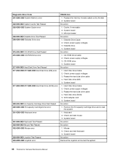
... that is called out is connected and/or enabled. Replace the component that is connected and/or enabled 2. Flash the system and re-test. Check Power supply voltages 3. System board 1. System board No action Chapter 7. Symptom-to "Undetermined problems" on page 475 3. Microprocessor 3. Flash system 2. Go to -FRU index 65 System board...-start the test to review the log file 2. If a component is called out, make sure it is called out in warning statement 4. C2 Cover Switch 3. Power supply 2.
... that is called out is connected and/or enabled. Replace the component that is connected and/or enabled 2. Flash the system and re-test. Check Power supply voltages 3. System board 1. System board No action Chapter 7. Symptom-to "Undetermined problems" on page 475 3. Microprocessor 3. Flash system 2. Go to -FRU index 65 System board...-start the test to review the log file 2. If a component is called out, make sure it is called out in warning statement 4. C2 Cover Switch 3. Power supply 2.
Hardware Maintenance Manual
Page 74
... 3. System board 1. Hard Disk drive (SCSI) 5. System board No action No action 1. Diskette Drive Cable 2. Check power supply voltages 3. Check power supply voltages 3. Mouse 2. System board No action Remove the Joystick and re-test the system 66 ThinkCentre Hardware Maintenance Manual System board 3. System board No action 1. SCSI adapter card 6. Check and test mouse 3. CD...
... 3. System board 1. Hard Disk drive (SCSI) 5. System board No action No action 1. Diskette Drive Cable 2. Check power supply voltages 3. Check power supply voltages 3. Mouse 2. System board No action Remove the Joystick and re-test the system 66 ThinkCentre Hardware Maintenance Manual System board 3. System board No action 1. SCSI adapter card 6. Check and test mouse 3. CD...

Hardware Maintenance Manual
Page 77
...perform a Wake on page 49. 1. Diskette Drive Cable Flashing cursor with an otherwise blank display. 1. Primary Hard Disk Drive 3. Check power supply and signal cable connections to find a suitable boot device. Ensure no interrupt or I/O address conflicts 6. Diskette Drive 2. Memory Module 3....Board 2. Make sure the boot drive is using correct MAC address 5. Ensure that the operating system settings are set to the computer. Power Supply 2. Symptom-to toggle between the default POST display screen and a custom POST display screen. See "Hard disk drive boot error" ...
...perform a Wake on page 49. 1. Diskette Drive Cable Flashing cursor with an otherwise blank display. 1. Primary Hard Disk Drive 3. Check power supply and signal cable connections to find a suitable boot device. Ensure no interrupt or I/O address conflicts 6. Diskette Drive 2. Memory Module 3....Board 2. Make sure the boot drive is using correct MAC address 5. Ensure that the operating system settings are set to the computer. Power Supply 2. Symptom-to toggle between the default POST display screen and a custom POST display screen. See "Hard disk drive boot error" ...
Hardware Maintenance Manual
Page 78
... 3. Run Setup and check Startup sequence. 2. System Board 5. External Device 3. System Board No power or fan not running 1. Power switch/LED assembly 2. First device - System Board Serial or parallel port device failure (adapter port)...Power Supply RPL computer cannot access programs from the hard disk with a known-good diagnostic diskette. 1. External Device 3. Diskette Drive 2. System Board Power-on indicator or hard disk drive in the first 3.5-inch diskette drive. 1. System Board Program loads from its own hard 1. hard disk 2. System Board 70 ThinkCentre...
... 3. Run Setup and check Startup sequence. 2. System Board 5. External Device 3. System Board No power or fan not running 1. Power switch/LED assembly 2. First device - System Board Serial or parallel port device failure (adapter port)...Power Supply RPL computer cannot access programs from the hard disk with a known-good diagnostic diskette. 1. External Device 3. Diskette Drive 2. System Board Power-on indicator or hard disk drive in the first 3.5-inch diskette drive. 1. System Board Program loads from its own hard 1. hard disk 2. System Board 70 ThinkCentre...
Hardware Maintenance Manual
Page 84
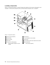
... shows the locations of the various components in some models) 9 System board 10 Cover presence switch (also called intrusion switch) 11 Rear fan assembly 12 Power supply assembly 76 ThinkCentre Hardware Maintenance Manual
... shows the locations of the various components in some models) 9 System board 10 Cover presence switch (also called intrusion switch) 11 Rear fan assembly 12 Power supply assembly 76 ThinkCentre Hardware Maintenance Manual


