Hardware Maintenance Manual for ThinkCentre M90z
Page 5
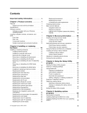
...disk drive password 40 Setting, changing, or deleting a password . . 40 Enabling or disabling a device 41 Selecting a startup device 41 © Copyright Lenovo 2010, 2012 Selecting a temporary startup device . . . . 41 Viewing or changing the startup device sequence 41 Exiting the Setup Utility program 42 Chapter ... FRU locations 69 System board connectors 70 Removing the computer cover 71 Removing or reinstalling the frame stand . . . . 72 Removing or reinstalling the lift stand 72 Removing or reinstalling the rear I/O assembly cover 74 Removing or reinstalling the wall mount cover ...
...disk drive password 40 Setting, changing, or deleting a password . . 40 Enabling or disabling a device 41 Selecting a startup device 41 © Copyright Lenovo 2010, 2012 Selecting a temporary startup device . . . . 41 Viewing or changing the startup device sequence 41 Exiting the Setup Utility program 42 Chapter ... FRU locations 69 System board connectors 70 Removing the computer cover 71 Removing or reinstalling the frame stand . . . . 72 Removing or reinstalling the lift stand 72 Removing or reinstalling the rear I/O assembly cover 74 Removing or reinstalling the wall mount cover ...

Hardware Maintenance Manual for ThinkCentre M90z
Page 9
...areas so that you think are : hammering, drilling, soldering, cutting wire, attaching springs, using solvents, or working on electrical equipment. © Copyright Lenovo 2010, 2012 3 Observe the following rules when working in any action that other service representatives and the customer's personnel are not in a hazardous position... current from the muscles in the installation and configuration procedures. Safety information This chapter contains the safety information that can stand safely without slipping. 2. Lift by standing or by pushing up above your feet. 3.
...areas so that you think are : hammering, drilling, soldering, cutting wire, attaching springs, using solvents, or working on electrical equipment. © Copyright Lenovo 2010, 2012 3 Observe the following rules when working in any action that other service representatives and the customer's personnel are not in a hazardous position... current from the muscles in the installation and configuration procedures. Safety information This chapter contains the safety information that can stand safely without slipping. 2. Lift by standing or by pushing up above your feet. 3.
Hardware Maintenance Manual for ThinkCentre M90z
Page 10
... units. (This practice ensures correct grounding of maintenance information. Remember: There must be a complete circuit to get medical aid. 4 ThinkCentre Hardware Maintenance Manual Switch off the wall box that another person to cause electrical shock. Performing a mechanical inspection - Use only one .... - Pumps - such touching can then operate the switch or unplug the power cord quickly. • Do not work area. Stand on a machine that contain small conductive fibers to insulate you . Blowers and fans - By observing the above rule, you can ...
... units. (This practice ensures correct grounding of maintenance information. Remember: There must be a complete circuit to get medical aid. 4 ThinkCentre Hardware Maintenance Manual Switch off the wall box that another person to cause electrical shock. Performing a mechanical inspection - Use only one .... - Pumps - such touching can then operate the switch or unplug the power cord quickly. • Do not work area. Stand on a machine that contain small conductive fibers to insulate you . Blowers and fans - By observing the above rule, you can ...
Hardware Maintenance Manual for ThinkCentre M90z
Page 36
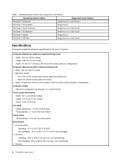
... inches) (varies by configuration) Computer dimensions (with stand and frame foot) • Width: 560 mm (22.05 inches) • ...421.9 mm (16.61 inches) (with frame stand and frame foot) - 566.9 mm (22.32 inches) (with lift stand) • Depth: ranges from 109 mm (4.29...mm (0.08 inches) Lift stand Height adjustment: 110 mm (4.33 inches) Tilt adjustment: -5° to 25° from the vertical Frame stand Tilt adjustment: 15°...m) Non-operating: -50 to 35 000 ft (-15.2 to : http://www.lenovo.com/support/ Specifications This section lists the physical specifications for your computer. • ...
... inches) (varies by configuration) Computer dimensions (with stand and frame foot) • Width: 560 mm (22.05 inches) • ...421.9 mm (16.61 inches) (with frame stand and frame foot) - 566.9 mm (22.32 inches) (with lift stand) • Depth: ranges from 109 mm (4.29...mm (0.08 inches) Lift stand Height adjustment: 110 mm (4.33 inches) Tilt adjustment: -5° to 25° from the vertical Frame stand Tilt adjustment: 15°...m) Non-operating: -50 to 35 000 ft (-15.2 to : http://www.lenovo.com/support/ Specifications This section lists the physical specifications for your computer. • ...

Hardware Maintenance Manual for ThinkCentre M90z
Page 75
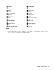
FRU locations The following illustration shows the locations of the FRUs. Component locations 1 Frame stand 2 Wall mount cover 3 Fan duct 4 Heat sink 5 Memory modules (2) 6 WI-FI card* 7 Microprocessor fan 8 Battery 9 ExpressCard* 10 Rear I/O assembly 11 Internal speaker 12 Bluetooth module* 17 Touch panel control board 18 Power switch module 19 Hard disk drive 20 Right I/O assembly 21 Card reader* 22 Optical drive bay 23 Inverter 24 Computer main bracket 25 LCD panel 26 Optical drive* 27 Power supply 28 Integrated camera with microphone* Chapter 8. Figure 3. Replacing FRUs 69
FRU locations The following illustration shows the locations of the FRUs. Component locations 1 Frame stand 2 Wall mount cover 3 Fan duct 4 Heat sink 5 Memory modules (2) 6 WI-FI card* 7 Microprocessor fan 8 Battery 9 ExpressCard* 10 Rear I/O assembly 11 Internal speaker 12 Bluetooth module* 17 Touch panel control board 18 Power switch module 19 Hard disk drive 20 Right I/O assembly 21 Card reader* 22 Optical drive bay 23 Inverter 24 Computer main bracket 25 LCD panel 26 Optical drive* 27 Power supply 28 Integrated camera with microphone* Chapter 8. Figure 3. Replacing FRUs 69

Hardware Maintenance Manual for ThinkCentre M90z
Page 78
... outlets and disconnect all attached devices and the computer. Place a soft, clean towel or cloth on how to remove or reinstall the frame stand. Hold the sides of your computer and gently lay it in the computer wall mount and then install the four screws to "Completing the ... down so that the screen is against the surface and the cover is facing up . 72 ThinkCentre Hardware Maintenance Manual This section provides instructions on the desk or surface. To remove or reinstall the lift stand, do the following : 1. Place a soft, clean towel or cloth on how to remove or...
... outlets and disconnect all attached devices and the computer. Place a soft, clean towel or cloth on how to remove or reinstall the frame stand. Hold the sides of your computer and gently lay it in the computer wall mount and then install the four screws to "Completing the ... down so that the screen is against the surface and the cover is facing up . 72 ThinkCentre Hardware Maintenance Manual This section provides instructions on the desk or surface. To remove or reinstall the lift stand, do the following : 1. Place a soft, clean towel or cloth on how to remove or...

Hardware Maintenance Manual for ThinkCentre M90z
Page 79
...the lift stand 4. Chapter 8. Remove the lift stand from the computer. To reinstall the lift stand, insert the two tabs 1 on the lift stand into the corresponding holes in the computer wall mount and then install the three screws to secure the lift stand. Align the three screw holes in the lift stand with ...those in the computer wall mount, and then slide the lift stand toward the bottom of the computer. 3. Keep the three screws, and put them...
...the lift stand 4. Chapter 8. Remove the lift stand from the computer. To reinstall the lift stand, insert the two tabs 1 on the lift stand into the corresponding holes in the computer wall mount and then install the three screws to secure the lift stand. Align the three screw holes in the lift stand with ...those in the computer wall mount, and then slide the lift stand toward the bottom of the computer. 3. Keep the three screws, and put them...

Hardware Maintenance Manual for ThinkCentre M90z
Page 80
Reinstalling the lift stand 5. To remove or reinstall the rear I /O assembly cover. Remove all media from the drives and turn off all cables that the screen is against the ... computer and gently lay it down so that are connected to the computer. 2. Then, disconnect all power cords from the computer wall mount cover. 74 ThinkCentre Hardware Maintenance Manual Removing or reinstalling the rear I /O assembly cover from electrical outlets and disconnect all attached devices and the computer. Figure 8. Remove the computer...
Reinstalling the lift stand 5. To remove or reinstall the rear I /O assembly cover. Remove all media from the drives and turn off all cables that the screen is against the ... computer and gently lay it down so that are connected to the computer. 2. Then, disconnect all power cords from the computer wall mount cover. 74 ThinkCentre Hardware Maintenance Manual Removing or reinstalling the rear I /O assembly cover from electrical outlets and disconnect all attached devices and the computer. Figure 8. Remove the computer...

Hardware Maintenance Manual for ThinkCentre M90z
Page 81
... power cords from the wall mount. See "Removing the computer cover" on page 72. 6. See "Removing or reinstalling the frame stand" on page 72 or "Removing or reinstalling the lift stand" on page 71. 4. Remove the screw that secures the wall mount cover, slide the wall mount cover to the bottom of... 8. Removing or reinstalling the wall mount cover To remove or reinstall the wall mount cover, do the following: 1. Remove the computer cover. Remove the frame stand or lift...
... power cords from the wall mount. See "Removing the computer cover" on page 72. 6. See "Removing or reinstalling the frame stand" on page 72 or "Removing or reinstalling the lift stand" on page 71. 4. Remove the screw that secures the wall mount cover, slide the wall mount cover to the bottom of... 8. Removing or reinstalling the wall mount cover To remove or reinstall the wall mount cover, do the following: 1. Remove the computer cover. Remove the frame stand or lift...

Hardware Maintenance Manual for ThinkCentre M90z
Page 82
...the computer main bracket and then lift the wall mount off all power cords from the drives and turn off the computer main bracket. 76 ThinkCentre Hardware Maintenance Manual Hold the sides of your computer and gently lay it down so that secure the wall mount to the computer. 2. See... attached devices and the computer. Remove the rear I/O assembly cover from the system board. See "Removing or reinstalling the frame stand" on page 72 or "Removing or reinstalling the lift stand" on page 75. 7. Removing the wall mount cover 7. To reinstall the wall mount cover, align the screw hole in...
...the computer main bracket and then lift the wall mount off all power cords from the drives and turn off the computer main bracket. 76 ThinkCentre Hardware Maintenance Manual Hold the sides of your computer and gently lay it down so that secure the wall mount to the computer. 2. See... attached devices and the computer. Remove the rear I/O assembly cover from the system board. See "Removing or reinstalling the frame stand" on page 72 or "Removing or reinstalling the lift stand" on page 75. 7. Removing the wall mount cover 7. To reinstall the wall mount cover, align the screw hole in...

Hardware Maintenance Manual for ThinkCentre M90z
Page 102
.... 10. Replacing the card reader Attention Do not open your computer. Remove the frame stand or lift stand. Remove the three screws 1 that came with those in the ThinkCentre Safety and Warranty Guide that secure the microprocessor fan assembly and then lift the microprocessor fan...page 72. 5. Connect the microprocessor fan assembly cable to :http://www.lenovo.com/support 96 ThinkCentre Hardware Maintenance Manual See "Removing or reinstalling the frame stand" on page 72 or "Removing or reinstalling the lift stand" on page 75. 7. Position the new microprocessor fan assembly on page...
.... 10. Replacing the card reader Attention Do not open your computer. Remove the frame stand or lift stand. Remove the three screws 1 that came with those in the ThinkCentre Safety and Warranty Guide that secure the microprocessor fan assembly and then lift the microprocessor fan...page 72. 5. Connect the microprocessor fan assembly cable to :http://www.lenovo.com/support 96 ThinkCentre Hardware Maintenance Manual See "Removing or reinstalling the frame stand" on page 72 or "Removing or reinstalling the lift stand" on page 75. 7. Position the new microprocessor fan assembly on page...

Hardware Maintenance Manual for ThinkCentre M90z
Page 116
... the LCD panel and main bracket assembly over the LCD panel, make sure the four screw holes in the main bracket align with the mounting stands in the LCD panel. 10. Go to reinstall the computer cover and reconnect cables. This will allow the four screws to the front bezel. 13... the four screws that secure the main bracket to be installed correctly. 11. To reinstall the computer cover and reconnect cables, do the following: 110 ThinkCentre Hardware Maintenance Manual
... the LCD panel and main bracket assembly over the LCD panel, make sure the four screw holes in the main bracket align with the mounting stands in the LCD panel. 10. Go to reinstall the computer cover and reconnect cables. This will allow the four screws to the front bezel. 13... the four screws that secure the main bracket to be installed correctly. 11. To reinstall the computer cover and reconnect cables, do the following: 110 ThinkCentre Hardware Maintenance Manual

Hardware Maintenance Manual for ThinkCentre M90z
Page 120
Item # 1 1 1 FRUs Frame stand (does not include frame foot - 03T8001) • MT 0800: all models • MT 0852: all models • MT 0870: all models &#...: all models • MT 3429: all models • MT 3650: all models • MT 5205: all models • MT 5248: all models Lift stand • MT 0800: all models • MT 0852: all models • MT 0870: all models • MT 2471: all models • MT 2557... • MT 3650: all models • MT 5205: all models • MT 5248: all models FRU # CRU 45K6428 2 03T8001 2 89Y1142 2 114 ThinkCentre Hardware Maintenance Manual
Item # 1 1 1 FRUs Frame stand (does not include frame foot - 03T8001) • MT 0800: all models • MT 0852: all models • MT 0870: all models &#...: all models • MT 3429: all models • MT 3650: all models • MT 5205: all models • MT 5248: all models Lift stand • MT 0800: all models • MT 0852: all models • MT 0870: all models • MT 2471: all models • MT 2557... • MT 3650: all models • MT 5205: all models • MT 5248: all models FRU # CRU 45K6428 2 03T8001 2 89Y1142 2 114 ThinkCentre Hardware Maintenance Manual

Hardware Maintenance Manual for ThinkCentre M90z
Page 144
...; MT 3429: all models • MT 3650: all models • MT 5205: all models • MT 5248: all models Lift stand kit • MT 0800: all models • MT 0852: all models • MT 0870: all models • MT 2471: all...MT 3429: all models • MT 3650: all models • MT 5205: all models • MT 5248: all models No-frame stand hole plug • MT 0800: all models • MT 0852: all models • MT 0870: all models • MT 2471...8226; MT 5205: all models • MT 5248: all models FRU # CRU 89Y1168 2 89Y1142 2 89Y1175 2 138 ThinkCentre Hardware Maintenance Manual
...; MT 3429: all models • MT 3650: all models • MT 5205: all models • MT 5248: all models Lift stand kit • MT 0800: all models • MT 0852: all models • MT 0870: all models • MT 2471: all...MT 3429: all models • MT 3650: all models • MT 5205: all models • MT 5248: all models No-frame stand hole plug • MT 0800: all models • MT 0852: all models • MT 0870: all models • MT 2471...8226; MT 5205: all models • MT 5248: all models FRU # CRU 89Y1168 2 89Y1142 2 89Y1175 2 138 ThinkCentre Hardware Maintenance Manual

Hardware Maintenance Manual for ThinkCentre M90z
Page 150
FRUs FRU, Mylar sheet for none stand mode • MT 0800: all models • MT 0852: all models • MT 0870: all models • MT 2471: all ...MT 3429: all models • MT 3650: all models • MT 5205: all models • MT 5248: all models FRU, blue hook for Y stand • MT 0800: all models • MT 0852: all models • MT 0870: all models • MT 2471: all models • MT ...; MT 3429: all models • MT 3650: all models • MT 5205: all models • MT 5248: all models 144 ThinkCentre Hardware Maintenance Manual FRU # CRU 03T9612 2 03T9665 2 03T9674 2
FRUs FRU, Mylar sheet for none stand mode • MT 0800: all models • MT 0852: all models • MT 0870: all models • MT 2471: all ...MT 3429: all models • MT 3650: all models • MT 5205: all models • MT 5248: all models FRU, blue hook for Y stand • MT 0800: all models • MT 0852: all models • MT 0870: all models • MT 2471: all models • MT ...; MT 3429: all models • MT 3650: all models • MT 5205: all models • MT 5248: all models 144 ThinkCentre Hardware Maintenance Manual FRU # CRU 03T9612 2 03T9665 2 03T9674 2
Hardware Maintenance Manual for ThinkCentre M90z
Page 285
...C card reader, replacing 96 changing startup device sequence 41 computer cover removing 71 computer cover, reinstalling 110 computer lift stand 72 removing 72 connectors front 67 considerations, password 40 CRU completing the installation 110 E environment, operating 31 exiting, Setup... camera with microphone, replacing 94 internal speakers, replacing 93 inverter, replacing 101 © Copyright Lenovo 2010, 2012 L LCD panel, replacing 109 Lenovo Solution Center 35 Lenovo ThinkVantage Toolbox 35 M memory module installing 77 system board 77 microprocessor fan assembly, replacing 95 multi...
...C card reader, replacing 96 changing startup device sequence 41 computer cover removing 71 computer cover, reinstalling 110 computer lift stand 72 removing 72 connectors front 67 considerations, password 40 CRU completing the installation 110 E environment, operating 31 exiting, Setup... camera with microphone, replacing 94 internal speakers, replacing 93 inverter, replacing 101 © Copyright Lenovo 2010, 2012 L LCD panel, replacing 109 Lenovo Solution Center 35 Lenovo ThinkVantage Toolbox 35 M memory module installing 77 system board 77 microprocessor fan assembly, replacing 95 multi...
(English) User Guide
Page 5
... Installing a computer wall mount 13 Removing the computer cover 14 Removing or reinstalling the frame stand . . 14 Removing or reinstalling the lift stand . . . . 15 Removing or reinstalling the rear I /O assembly. . . . . . 44 Replacing the power supply 45 © Copyright Lenovo 2010, 2012 Replacing the keyboard 47 Replacing the mouse 49 Completing the parts replacement...
... Installing a computer wall mount 13 Removing the computer cover 14 Removing or reinstalling the frame stand . . 14 Removing or reinstalling the lift stand . . . . 15 Removing or reinstalling the rear I /O assembly. . . . . . 44 Replacing the power supply 45 © Copyright Lenovo 2010, 2012 Replacing the keyboard 47 Replacing the mouse 49 Completing the parts replacement...
(English) User Guide
Page 12
...Width: 560 mm (22.05 inches) • Maximum height: - 421.9 mm (16.61 inches) (with a frame stand and frame foot) - 566.9 mm (22.32 inches) (with a lift stand) • Depth: ranges from 109 mm (4.29 inches) to 250 mm (9.84 inches) (varies by configuration) Computer weight...: 20% to 80% (10% per hour, non-condensing) Non-operating: 20% to 80% (10% per hour, non-condensing) • Altitude: 4 ThinkCentre User Guide Operating system edition and supported touch feature Operating system edition Windows 7 Enterprise Supported touch feature Single-touch or multi-touch Windows 7 Home Basic...
...Width: 560 mm (22.05 inches) • Maximum height: - 421.9 mm (16.61 inches) (with a frame stand and frame foot) - 566.9 mm (22.32 inches) (with a lift stand) • Depth: ranges from 109 mm (4.29 inches) to 250 mm (9.84 inches) (varies by configuration) Computer weight...: 20% to 80% (10% per hour, non-condensing) Non-operating: 20% to 80% (10% per hour, non-condensing) • Altitude: 4 ThinkCentre User Guide Operating system edition and supported touch feature Operating system edition Windows 7 Enterprise Supported touch feature Single-touch or multi-touch Windows 7 Home Basic...
(English) User Guide
Page 19
...* 28 VESA frame Notes: 1. * denotes optional parts, which are available in some models. 2. For more information about the lift stand, see "Removing or reinstalling the lift stand" on page 15. Product overview 11 1 Frame stand 2 Video Electronics Standards Association (VESA) frame cover 3 Fan duct 4 Heat sink 5 Memory modules (2) 6 WI-FI card* 7 Microprocessor fan... I/O assembly 19 Card reader* 20 Optical drive bay 21 Inverter 22 Computer main bracket 23 Optical drive* 24 Power supply 25 Integrated camera with a frame stand or a lift...
...* 28 VESA frame Notes: 1. * denotes optional parts, which are available in some models. 2. For more information about the lift stand, see "Removing or reinstalling the lift stand" on page 15. Product overview 11 1 Frame stand 2 Video Electronics Standards Association (VESA) frame cover 3 Fan duct 4 Heat sink 5 Memory modules (2) 6 WI-FI card* 7 Microprocessor fan... I/O assembly 19 Card reader* 20 Optical drive bay 21 Inverter 22 Computer main bracket 23 Optical drive* 24 Power supply 25 Integrated camera with a frame stand or a lift...

(English) User Guide
Page 22
... that are connected to let the computer cool before reading and understanding the "Important safety information" in the ThinkCentre Safety and Warranty Guide that came with a frame stand or a lift stand. CAUTION: Turn off the computer and wait three to five minutes to the computer. 2. Remove any repair..., such as shown, slide the computer cover toward the top of the ThinkCentre Safety and Warranty Guide, go to: http://www.lenovo.com/support This section provides instructions on how to the computer. 14 ThinkCentre User Guide Remove all media from the drives and turn off all attached...
... that are connected to let the computer cool before reading and understanding the "Important safety information" in the ThinkCentre Safety and Warranty Guide that came with a frame stand or a lift stand. CAUTION: Turn off the computer and wait three to five minutes to the computer. 2. Remove any repair..., such as shown, slide the computer cover toward the top of the ThinkCentre Safety and Warranty Guide, go to: http://www.lenovo.com/support This section provides instructions on how to the computer. 14 ThinkCentre User Guide Remove all media from the drives and turn off all attached...


