(English) Rescue and Recovery 4.3 Deployment Guide
Page 34
... Setting the base backup location: The following registry entry will be installed again to be backed up every incremental. [HKEY_LOCAL_MACHINE\SOFTWARE\Policies\Lenovo\Rescue and Recovery\Settings\Backup \PreBackup] "Pre"="cmd" "PreParameters"="/c attrib +A \"%windir%\\system32\\msmq\\*.*\" /S /D" "PreShow"=dword:00000000 ...get out of backups. Here are using MSMQ, you to perform numerous types of synch and cause the service to an AC power supply before the Rescue and Recovery program takes a backup that run a command before initiating a backup, restore, rejuvenation, or archive...
... Setting the base backup location: The following registry entry will be installed again to be backed up every incremental. [HKEY_LOCAL_MACHINE\SOFTWARE\Policies\Lenovo\Rescue and Recovery\Settings\Backup \PreBackup] "Pre"="cmd" "PreParameters"="/c attrib +A \"%windir%\\system32\\msmq\\*.*\" /S /D" "PreShow"=dword:00000000 ...get out of backups. Here are using MSMQ, you to perform numerous types of synch and cause the service to an AC power supply before the Rescue and Recovery program takes a backup that run a command before initiating a backup, restore, rejuvenation, or archive...
(English) Rescue and Recovery 4.5 Deployment Guide
Page 28
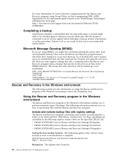
...user message: ThinkVantage\Rescue and Recovery\Settings\User Messages For more information on the ThinkVantage Technologies Administrator Tools page: http://support.lenovo.com/en_US/detail.page?LegacyDocID=TVAN-ADMIN#rnr Completing a backup Applications installed or uninstalled after a restore operation from all of ...not exist. • The User ID documents settings are attempting to an AC power supply before the 22 Rescue and Recovery 4.5 Deployment Guide That is connected to backup has 1% remaining battery power, set . • Potential data loss Deleting the user ID in data loss ...
...user message: ThinkVantage\Rescue and Recovery\Settings\User Messages For more information on the ThinkVantage Technologies Administrator Tools page: http://support.lenovo.com/en_US/detail.page?LegacyDocID=TVAN-ADMIN#rnr Completing a backup Applications installed or uninstalled after a restore operation from all of ...not exist. • The User ID documents settings are attempting to an AC power supply before the 22 Rescue and Recovery 4.5 Deployment Guide That is connected to backup has 1% remaining battery power, set . • Potential data loss Deleting the user ID in data loss ...
Hardware Maintenance Manual for ThinkCentre M90z
Page 5
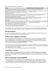
... error 43 Power Supply Problems 43 Diagnostic error codes 44 Beep symptoms 61 POST error codes 62 Miscellaneous error conditions 63 Undetermined problems 64 Chapter 8. Contents Chapter 1. General information . . . . 29 Lenovo ThinkVantage Tools 29 SimpleTap 29 Lenovo Solution Center ... . . 95 Replacing the card reader 96 Replacing the rear I/O assembly 97 Replacing the right I/O assembly 99 Replacing the power supply 100 Replacing the inverter 101 iii Safety information 3 General safety 3 Electrical safety 3 Safety inspection guide 5 Handling electrostatic discharge-...
... error 43 Power Supply Problems 43 Diagnostic error codes 44 Beep symptoms 61 POST error codes 62 Miscellaneous error conditions 63 Undetermined problems 64 Chapter 8. Contents Chapter 1. General information . . . . 29 Lenovo ThinkVantage Tools 29 SimpleTap 29 Lenovo Solution Center ... . . 95 Replacing the card reader 96 Replacing the rear I/O assembly 97 Replacing the right I/O assembly 99 Replacing the power supply 100 Replacing the inverter 101 iii Safety information 3 General safety 3 Electrical safety 3 Safety inspection guide 5 Handling electrostatic discharge-...
Hardware Maintenance Manual for ThinkCentre M90z
Page 10
...Working near equipment that another person to work on the machine, unplug the power cord. Removing or installing Field Replaceable Units (FRUs) • Before you start to get medical aid. 4 ThinkCentre Hardware Maintenance Manual keep the other hand in the safety sections of maintenance ...units.) • If an electrical accident occurs: - If an electrical accident occurs, you work alone under hazardous conditions or near power supplies - Use only one hand when working with very high voltages; Remember: There must be a complete circuit to decrease electrostatic discharges. ...
...Working near equipment that another person to work on the machine, unplug the power cord. Removing or installing Field Replaceable Units (FRUs) • Before you start to get medical aid. 4 ThinkCentre Hardware Maintenance Manual keep the other hand in the safety sections of maintenance ...units.) • If an electrical accident occurs: - If an electrical accident occurs, you work alone under hazardous conditions or near power supplies - Use only one hand when working with very high voltages; Remember: There must be a complete circuit to decrease electrostatic discharges. ...

Hardware Maintenance Manual for ThinkCentre M90z
Page 11
...Check inside the unit for any alterations. 6. Use product-specific ESD procedures when they present: • Electrical hazards, especially primary power (primary voltage on these conditions and the safety hazards they exceed the requirements noted here. 2. If any obvious unsafe conditions, such... installed to assist you use have not been removed or tampered with the power off the computer. Chapter 2. Safety inspection guide The intent of this inspection guide. Make sure that the power-supply cover fasteners (screws or rivets) have been certified (ISO 9000) as ...
...Check inside the unit for any alterations. 6. Use product-specific ESD procedures when they present: • Electrical hazards, especially primary power (primary voltage on these conditions and the safety hazards they exceed the requirements noted here. 2. If any obvious unsafe conditions, such... installed to assist you use have not been removed or tampered with the power off the computer. Chapter 2. Safety inspection guide The intent of this inspection guide. Make sure that the power-supply cover fasteners (screws or rivets) have been certified (ISO 9000) as ...

Hardware Maintenance Manual for ThinkCentre M90z
Page 14
≥18 kg (37 lbs) ≥32 kg (70.5 lbs) ≥55 kg (121.2 lbs) CAUTION: Use safe practices when lifting. CAUTION: The power control button on the device and the power switch on the power supply do not turn off the electrical current supplied to the device. To remove all electrical current from the device, ensure that all power cords are disconnected from the power source. 2 1 8 ThinkCentre Hardware Maintenance Manual The device also might have more than one power cord.
≥18 kg (37 lbs) ≥32 kg (70.5 lbs) ≥55 kg (121.2 lbs) CAUTION: Use safe practices when lifting. CAUTION: The power control button on the device and the power switch on the power supply do not turn off the electrical current supplied to the device. To remove all electrical current from the device, ensure that all power cords are disconnected from the power source. 2 1 8 ThinkCentre Hardware Maintenance Manual The device also might have more than one power cord.

Hardware Maintenance Manual for ThinkCentre M90z
Page 49
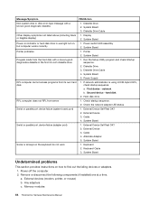
...following for proper installation. • Power cord • On/Off switch connector • On/Off switch power supply connector • System board power supply connectors • Microprocessor(s) connection Check the power cord for a description of your error symptoms in configuration. Power Supply Problems If you are unable to .... Install an operating system on page 33. Check/Verify Check the following : 1. Check the power-on switch © Copyright Lenovo 2010, 2012 43 Chapter 7. Error The start -up drive is in the boot sequence. FRU/Action Reseat connectors...
...following for proper installation. • Power cord • On/Off switch connector • On/Off switch power supply connector • System board power supply connectors • Microprocessor(s) connection Check the power cord for a description of your error symptoms in configuration. Power Supply Problems If you are unable to .... Install an operating system on page 33. Check/Verify Check the following : 1. Check the power-on switch © Copyright Lenovo 2010, 2012 43 Chapter 7. Error The start -up drive is in the boot sequence. FRU/Action Reseat connectors...

Hardware Maintenance Manual for ThinkCentre M90z
Page 59
... is called out is connected and/or enabled. Flash the system and re-test. System board Chapter 7. IDE signal cable 2. Riser card, if installed. 3. Check power supply voltages. 3. Riser card, if installed. 3. See "Flash update procedures" on page 273. 3. See Chapter 6 "Using the Setup Utility program" on page 39...
... is called out is connected and/or enabled. Flash the system and re-test. System board Chapter 7. IDE signal cable 2. Riser card, if installed. 3. Check power supply voltages. 3. Riser card, if installed. 3. See "Flash update procedures" on page 273. 3. See Chapter 6 "Using the Setup Utility program" on page 39...
Hardware Maintenance Manual for ThinkCentre M90z
Page 60
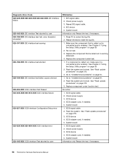
...page 64. 2. Re-run test. 3. Replace the component under function test. See "Flash update procedures" on page 273. 3. No action 1. Check power supply 3. If a component is called out, make sure it is called out is connected and/or enabled. Go to review the log file. 2. System board...2. Replace component under test. 1. SCSI adapter card, if installed. 5. System board Information only Restart the test, if necessary. 54 ThinkCentre Hardware Maintenance Manual Diagnostic Error Code 025-02X-XXX 025-03X-XXX 025-04X-XXX IDE Interface failure 025-195-XXX IDE interface Test aborted...
...page 64. 2. Re-run test. 3. Replace the component under function test. See "Flash update procedures" on page 273. 3. No action 1. Check power supply 3. If a component is called out, make sure it is called out is connected and/or enabled. Go to review the log file. 2. System board...2. Replace component under test. 1. SCSI adapter card, if installed. 5. System board Information only Restart the test, if necessary. 54 ThinkCentre Hardware Maintenance Manual Diagnostic Error Code 025-02X-XXX 025-03X-XXX 025-04X-XXX IDE Interface failure 025-195-XXX IDE interface Test aborted...

Hardware Maintenance Manual for ThinkCentre M90z
Page 65
... component that is called out in warning statement. 4. Flash the system and re-test. See "Undetermined problems" on page 64. 2. Check fans 2. Check power supply voltages. 3. Flash system 2. Power supply 2. Microprocessor 3. See "Flash update procedures" on page 39. 2. Flash the system and re-test. System board 185-278-XXX Asset Security Chassis Intrusion 1. Assure...
... component that is called out in warning statement. 4. Flash the system and re-test. See "Undetermined problems" on page 64. 2. Check fans 2. Check power supply voltages. 3. Flash system 2. Power supply 2. Microprocessor 3. See "Flash update procedures" on page 39. 2. Flash the system and re-test. System board 185-278-XXX Asset Security Chassis Intrusion 1. Assure...

Hardware Maintenance Manual for ThinkCentre M90z
Page 66
... board No action Remove the Joystick and re-test the system. 60 ThinkCentre Hardware Maintenance Manual Replace the memory module called out by the test. 2. Check power supply voltages 3. Reseat the hard disk drive cable 4. Cache, if removable 2. Diskette Drive Cable 2. Check power supply voltages 3. Diagnostic Error Code 201-XXX-XXX System Memory error 202...
... board No action Remove the Joystick and re-test the system. 60 ThinkCentre Hardware Maintenance Manual Replace the memory module called out by the test. 2. Check power supply voltages 3. Reseat the hard disk drive cable 4. Cache, if removable 2. Diskette Drive Cable 2. Check power supply voltages 3. Diagnostic Error Code 201-XXX-XXX System Memory error 202...

Hardware Maintenance Manual for ThinkCentre M90z
Page 69
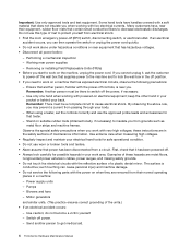
...address) Computer will not perform a Wake On LAN® (if applicable) 1. Power Supply 2. Diskette Drive 2. Run the Memory tests. 2. System Board 2. See "Hard disk drive boot error" on page 43. 1. Power Switch 2. Ensure no interrupt or I/O address conflicts. 6. Memory Module 3. Diskette ...operating system settings are set to right of characters and color bars 1. System Board 2. System Board No power or fan not running 1. Check power supply and signal cable connections to -FRU Index 63 Ensure network administrator is enabled for flashing cursor. 1. Chapter...
...address) Computer will not perform a Wake On LAN® (if applicable) 1. Power Supply 2. Diskette Drive 2. Run the Memory tests. 2. System Board 2. See "Hard disk drive boot error" on page 43. 1. Power Switch 2. Ensure no interrupt or I/O address conflicts. 6. Memory Module 3. Diskette ...operating system settings are set to right of characters and color bars 1. System Board 2. System Board No power or fan not running 1. Check power supply and signal cable connections to -FRU Index 63 Ensure network administrator is enabled for flashing cursor. 1. Chapter...
Hardware Maintenance Manual for ThinkCentre M90z
Page 70
Display 2. System Board Program loads from the hard disk with a known-good diagnostic diskette. 1. Diskette Drive 3. Power Supply RPL computer cannot access programs from server 1. Hard disk drive RPL computer does not RPL from its own hard 1. Cable 4. External Device Self-Test OK... not on, but computer works correctly 1. Diskette Drive 2. Remove or disconnect the following components (if installed) one at a time. Printer 2. Memory modules 64 ThinkCentre Hardware Maintenance Manual If network administrator is using LCCM Hybrid RPL, disk. Second device -
Display 2. System Board Program loads from the hard disk with a known-good diagnostic diskette. 1. Diskette Drive 3. Power Supply RPL computer cannot access programs from server 1. Hard disk drive RPL computer does not RPL from its own hard 1. Cable 4. External Device Self-Test OK... not on, but computer works correctly 1. Diskette Drive 2. Remove or disconnect the following components (if installed) one at a time. Printer 2. Memory modules 64 ThinkCentre Hardware Maintenance Manual If network administrator is using LCCM Hybrid RPL, disk. Second device -

Hardware Maintenance Manual for ThinkCentre M90z
Page 75
Component locations 1 Frame stand 2 Wall mount cover 3 Fan duct 4 Heat sink 5 Memory modules (2) 6 WI-FI card* 7 Microprocessor fan 8 Battery 9 ExpressCard* 10 Rear I/O assembly 11 Internal speaker 12 Bluetooth module* 17 Touch panel control board 18 Power switch module 19 Hard disk drive 20 Right I/O assembly 21 Card reader* 22 Optical drive bay 23 Inverter 24 Computer main bracket 25 LCD panel 26 Optical drive* 27 Power supply 28 Integrated camera with microphone* Chapter 8. Figure 3. Replacing FRUs 69 FRU locations The following illustration shows the locations of the FRUs.
Component locations 1 Frame stand 2 Wall mount cover 3 Fan duct 4 Heat sink 5 Memory modules (2) 6 WI-FI card* 7 Microprocessor fan 8 Battery 9 ExpressCard* 10 Rear I/O assembly 11 Internal speaker 12 Bluetooth module* 17 Touch panel control board 18 Power switch module 19 Hard disk drive 20 Right I/O assembly 21 Card reader* 22 Optical drive bay 23 Inverter 24 Computer main bracket 25 LCD panel 26 Optical drive* 27 Power supply 28 Integrated camera with microphone* Chapter 8. Figure 3. Replacing FRUs 69 FRU locations The following illustration shows the locations of the FRUs.

Hardware Maintenance Manual for ThinkCentre M90z
Page 77
...disconnect all power cords from the drives and turn off the computer and wait three to five minutes to remove the computer cover. Removing the computer cover Chapter 8. Replacing FRUs 71 To obtain a copy of the ThinkCentre Safety and Warranty Guide, go to:http://www.lenovo.com/... up . 3. 11 Microprocessor fan connector 12 Internal speaker cable connector 13 Power switch cable connector 14 ExpressCard connector 25 System fan connector 26 Inverter connector 27 Power supply fan connector 28 Power supply connector Removing the computer cover Attention Do not open your computer or attempt ...
...disconnect all power cords from the drives and turn off the computer and wait three to five minutes to remove the computer cover. Removing the computer cover Chapter 8. Replacing FRUs 71 To obtain a copy of the ThinkCentre Safety and Warranty Guide, go to:http://www.lenovo.com/... up . 3. 11 Microprocessor fan connector 12 Internal speaker cable connector 13 Power switch cable connector 14 ExpressCard connector 25 System fan connector 26 Inverter connector 27 Power supply fan connector 28 Power supply connector Removing the computer cover Attention Do not open your computer or attempt ...

Hardware Maintenance Manual for ThinkCentre M90z
Page 106
... 37 on page 69. 5. Note the routing of the ThinkCentre Safety and Warranty Guide, go to:http://www.lenovo.com/support This section provides instructions on how to the computer. 2. Lift the power supply up to the power cord connector bracket. 100 ThinkCentre Hardware Maintenance Manual See "FRU locations" on page 100) that the screen is...
... 37 on page 69. 5. Note the routing of the ThinkCentre Safety and Warranty Guide, go to:http://www.lenovo.com/support This section provides instructions on how to the computer. 2. Lift the power supply up to the power cord connector bracket. 100 ThinkCentre Hardware Maintenance Manual See "FRU locations" on page 100) that the screen is...

Hardware Maintenance Manual for ThinkCentre M90z
Page 107
... or reinstalling the rear I /O assembly" on page 71. 4. Go to the computer. 2. Hold the sides of the ThinkCentre Safety and Warranty Guide, go to the power supply connector on page 81. 7. Remove the optical drive. See "Replacing the card reader" on page 110. Remove the computer ..."Replacing the optical drive" on the system board. 10. To replace the inverter, do the following: 1. Connect the new power supply cable to :http://www.lenovo.com/support This section provides instructions on page 80. 6. To obtain a copy of your computer. See "Replacing the hard disk...
... or reinstalling the rear I /O assembly" on page 71. 4. Go to the computer. 2. Hold the sides of the ThinkCentre Safety and Warranty Guide, go to the power supply connector on page 81. 7. Remove the optical drive. See "Replacing the card reader" on page 110. Remove the computer ..."Replacing the optical drive" on the system board. 10. To replace the inverter, do the following: 1. Connect the new power supply cable to :http://www.lenovo.com/support This section provides instructions on page 80. 6. To obtain a copy of your computer. See "Replacing the hard disk...

Hardware Maintenance Manual for ThinkCentre M90z
Page 281
...). Chapter 10. Additional Service Information 275 Then, select the optical drive as the system power supply, processor, hard disk drives, and some monitors. Install the computer cover and reconnect all cables and power cords that is Wake on LAN-enabled and there is completed, the series of beeps....computer automatically. • Serial Port A Ring Detect: With this time you set to Enabled and an external modem connected to control the power management features of the computer such as the startup device and press Enter. Repeat steps 1 through 3. 10. Remove the disc from ...
...). Chapter 10. Additional Service Information 275 Then, select the optical drive as the system power supply, processor, hard disk drives, and some monitors. Install the computer cover and reconnect all cables and power cords that is Wake on LAN-enabled and there is completed, the series of beeps....computer automatically. • Serial Port A Ring Detect: With this time you set to Enabled and an external modem connected to control the power management features of the computer such as the startup device and press Enter. Repeat steps 1 through 3. 10. Remove the disc from ...
Hardware Maintenance Manual for ThinkCentre M90z
Page 285
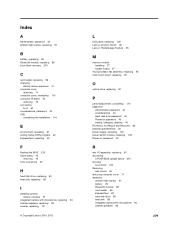
... integrated camera with microphone, replacing 94 internal speakers, replacing 93 inverter, replacing 101 © Copyright Lenovo 2010, 2012 L LCD panel, replacing 109 Lenovo Solution Center 35 Lenovo ThinkVantage Toolbox 35 M memory module installing 77 system board 77 microprocessor fan assembly, replacing 95 multi-touch... password 40 setting, changing, deleting 40 PC-Doctor for Rescue and Recovery 36 physical specifications 30 power supply, replacing 100 power switch module, replacing 103 Power-on password 40 R rear I/O assembly, replacing 97 recovering a POST/BIOS update failure 274 recovery...
... integrated camera with microphone, replacing 94 internal speakers, replacing 93 inverter, replacing 101 © Copyright Lenovo 2010, 2012 L LCD panel, replacing 109 Lenovo Solution Center 35 Lenovo ThinkVantage Toolbox 35 M memory module installing 77 system board 77 microprocessor fan assembly, replacing 95 multi-touch... password 40 setting, changing, deleting 40 PC-Doctor for Rescue and Recovery 36 physical specifications 30 power supply, replacing 100 power switch module, replacing 103 Power-on password 40 R rear I/O assembly, replacing 97 recovering a POST/BIOS update failure 274 recovery...
Hardware Maintenance Manual for ThinkCentre M90z
Page 286
inverter 101 LCD panel 109 microprocessor fan assembly 95 multi-touch board 90 power supply 100 power switch module 103 rear I/O assembly 97 right I/O assembly 99 system board 106 system fan 102 touch panel control board 105 WI-FI card 88 right I/O ... U updating (flashing) the BIOS 273 updating (flashing) the BIOS 274 using passwords 39 Setup Utility program 39 V viewing and changing settings 39 W wall mount 280 ThinkCentre Hardware Maintenance Manual Removing 76 WI-FI card, replacing 88
inverter 101 LCD panel 109 microprocessor fan assembly 95 multi-touch board 90 power supply 100 power switch module 103 rear I/O assembly 97 right I/O assembly 99 system board 106 system fan 102 touch panel control board 105 WI-FI card 88 right I/O ... U updating (flashing) the BIOS 273 updating (flashing) the BIOS 274 using passwords 39 Setup Utility program 39 V viewing and changing settings 39 W wall mount 280 ThinkCentre Hardware Maintenance Manual Removing 76 WI-FI card, replacing 88


