Hardware Maintenance Manual for ThinkCentre M90z
Page 5
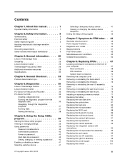
... multi-touch board 90 Replacing the ambient light sensor 91 Replacing the ExpressCard 92 Replacing the internal speakers 93 Replacing the integrated camera with microphone 94 Replacing the microprocessor fan assembly . . . 95 Replacing the card reader 96 Replacing the rear I/O assembly ...the Setup Utility program 42 Chapter 7. About this manual 1 Important Safety Information 1 Chapter 2. Contents Chapter 1. Diagnostics 35 Lenovo ThinkVantage Toolbox 35 Lenovo Solution Center 35 PC-Doctor for Rescue and Recovery 36 PC-Doctor for DOS 36 Creating a diagnostic disc 36 Running ...
... multi-touch board 90 Replacing the ambient light sensor 91 Replacing the ExpressCard 92 Replacing the internal speakers 93 Replacing the integrated camera with microphone 94 Replacing the microprocessor fan assembly . . . 95 Replacing the card reader 96 Replacing the rear I/O assembly ...the Setup Utility program 42 Chapter 7. About this manual 1 Important Safety Information 1 Chapter 2. Contents Chapter 1. Diagnostics 35 Lenovo ThinkVantage Toolbox 35 Lenovo Solution Center 35 PC-Doctor for Rescue and Recovery 36 PC-Doctor for DOS 36 Creating a diagnostic disc 36 Running ...

Hardware Maintenance Manual for ThinkCentre M90z
Page 73
... contain a removal and replacement procedure for all FRUs. Front control and part locations 1 Integrated camera with MIC (microphone) (available in some models) 2 Integrated camera on the front of your computer The following illustration shows the locations of your computer. Locating ...controls and connectors on the front of the controls and connectors on /off button 8 Wireless activity indicator 9 Menu/Enter © Copyright Lenovo 2010, 2012 67 ...
... contain a removal and replacement procedure for all FRUs. Front control and part locations 1 Integrated camera with MIC (microphone) (available in some models) 2 Integrated camera on the front of your computer The following illustration shows the locations of your computer. Locating ...controls and connectors on the front of the controls and connectors on /off button 8 Wireless activity indicator 9 Menu/Enter © Copyright Lenovo 2010, 2012 67 ...

Hardware Maintenance Manual for ThinkCentre M90z
Page 75
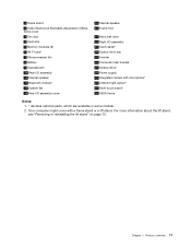
Figure 3. Component locations 1 Frame stand 2 Wall mount cover 3 Fan duct 4 Heat sink 5 Memory modules (2) 6 WI-FI card* 7 Microprocessor fan 8 Battery 9 ExpressCard* 10 Rear I/O assembly 11 Internal speaker 12 Bluetooth module* 17 Touch panel control board 18 Power switch module 19 Hard disk drive 20 Right I/O assembly 21 Card reader* 22 Optical drive bay 23 Inverter 24 Computer main bracket 25 LCD panel 26 Optical drive* 27 Power supply 28 Integrated camera with microphone* Chapter 8. FRU locations The following illustration shows the locations of the FRUs. Replacing FRUs 69
Figure 3. Component locations 1 Frame stand 2 Wall mount cover 3 Fan duct 4 Heat sink 5 Memory modules (2) 6 WI-FI card* 7 Microprocessor fan 8 Battery 9 ExpressCard* 10 Rear I/O assembly 11 Internal speaker 12 Bluetooth module* 17 Touch panel control board 18 Power switch module 19 Hard disk drive 20 Right I/O assembly 21 Card reader* 22 Optical drive bay 23 Inverter 24 Computer main bracket 25 LCD panel 26 Optical drive* 27 Power supply 28 Integrated camera with microphone* Chapter 8. FRU locations The following illustration shows the locations of the FRUs. Replacing FRUs 69
Hardware Maintenance Manual for ThinkCentre M90z
Page 76
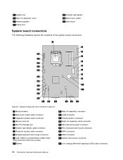
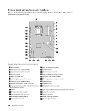
... 22 SATA connector 23 Optical drive power connector 24 Low-voltage differential signaling (LVDS) cable connector 70 ThinkCentre Hardware Maintenance Manual System board part and connector locations 1 Microprocessor 2 Multi-touch board cable connector 3 Integrated camera cable connector 4 Memory slots (2) 5 Mini PCI Express slot 6 Ambient light sensor cable connector 7 Bluetooth module cable connector...
... 22 SATA connector 23 Optical drive power connector 24 Low-voltage differential signaling (LVDS) cable connector 70 ThinkCentre Hardware Maintenance Manual System board part and connector locations 1 Microprocessor 2 Multi-touch board cable connector 3 Integrated camera cable connector 4 Memory slots (2) 5 Mini PCI Express slot 6 Ambient light sensor cable connector 7 Bluetooth module cable connector...
Hardware Maintenance Manual for ThinkCentre M90z
Page 100
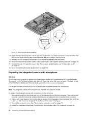
... 4. Go to the computer. 2. See "Removing the computer cover" on page 69. 94 ThinkCentre Hardware Maintenance Manual Reinstall the rear I /O assembly cover" on page 110. Note: The integrated camera with your computer and gently lay it down so that the screen is against the surface and ... devices and the computer. Removing the internal speakers 8. Reinstall the two screws to secure each of the ThinkCentre Safety and Warranty Guide, go to:http://www.lenovo.com/support This section provides instructions on the front bezel so that are connected to "Completing the parts ...
... 4. Go to the computer. 2. See "Removing the computer cover" on page 69. 94 ThinkCentre Hardware Maintenance Manual Reinstall the rear I /O assembly cover" on page 110. Note: The integrated camera with your computer and gently lay it down so that the screen is against the surface and ... devices and the computer. Removing the internal speakers 8. Reinstall the two screws to secure each of the ThinkCentre Safety and Warranty Guide, go to:http://www.lenovo.com/support This section provides instructions on the front bezel so that are connected to "Completing the parts ...
Hardware Maintenance Manual for ThinkCentre M90z
Page 101
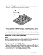
..." on how to the front bezel, and then remove the integrated camera with microphone to replace the microprocessor fan assembly. To obtain a copy of the ThinkCentre Safety and Warranty Guide, go to:http://www.lenovo.com/support This section provides instructions on page 110. Remove the two... screws 1 that secure the integrated camera with microphone from the drives and turn off all cables...
..." on how to the front bezel, and then remove the integrated camera with microphone to replace the microprocessor fan assembly. To obtain a copy of the ThinkCentre Safety and Warranty Guide, go to:http://www.lenovo.com/support This section provides instructions on page 110. Remove the two... screws 1 that secure the integrated camera with microphone from the drives and turn off all cables...

Hardware Maintenance Manual for ThinkCentre M90z
Page 136
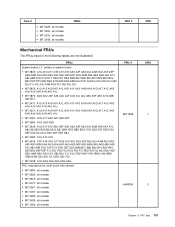
...Y4M Y7M Y8M G1M G2M G3M G4M G5J G6J G7J G8J G9J Y9J • MT 5248: A1G A2G A3G A4G A5G A6G Camera module with normal bracket • MT 0800: all models • MT 0852: all models • MT 0870: all ... • MT 3429: all models • MT 3650: all models • MT 5205: all models • MT 5248: all models Camera module with angled bracket • MT 0800: all models • MT 0852: all models • MT 0870: all models • MT...all models • MT 3091: all models • MT 3265: all models FRU # 89Y1170 89Y1168 45K6433 130 ThinkCentre Hardware Maintenance Manual CRU 1 1 2
...Y4M Y7M Y8M G1M G2M G3M G4M G5J G6J G7J G8J G9J Y9J • MT 5248: A1G A2G A3G A4G A5G A6G Camera module with normal bracket • MT 0800: all models • MT 0852: all models • MT 0870: all ... • MT 3429: all models • MT 3650: all models • MT 5205: all models • MT 5248: all models Camera module with angled bracket • MT 0800: all models • MT 0852: all models • MT 0870: all models • MT...all models • MT 3091: all models • MT 3265: all models FRU # 89Y1170 89Y1168 45K6433 130 ThinkCentre Hardware Maintenance Manual CRU 1 1 2
Hardware Maintenance Manual for ThinkCentre M90z
Page 137
... G1M G2M G3M G4M G5J G6J G7J G8J G9J Y9J • MT 5248: A1G A2G A3G A4G A5G A6G FRU, mechanical kit, multi touch with camera • MT 0800: all models • MT 0852: all models • MT 0870: all models • MT 2471: all models • MT 2557: all models...
... G1M G2M G3M G4M G5J G6J G7J G8J G9J Y9J • MT 5248: A1G A2G A3G A4G A5G A6G FRU, mechanical kit, multi touch with camera • MT 0800: all models • MT 0852: all models • MT 0870: all models • MT 2471: all models • MT 2557: all models...

Hardware Maintenance Manual for ThinkCentre M90z
Page 138
FRUs • MT 5205: all models • MT 5248: all models FRU, mechanical kit, non touch with camera • MT 0800: all models • MT 0852: all models • MT 0870: all models &#...8226; MT 3650: all models • MT 5205: all models • MT 5248: all models FRU, mechanical kit, non touch without camera • MT 0800: all models • MT 0852: all models • MT 0870: all models • MT 2471: all models...; MT 3650: all models • MT 5205: all models • MT 5248: all models 132 ThinkCentre Hardware Maintenance Manual FRU # CRU 45K6396 2 45K6397 2 89Y1175 2
FRUs • MT 5205: all models • MT 5248: all models FRU, mechanical kit, non touch with camera • MT 0800: all models • MT 0852: all models • MT 0870: all models &#...8226; MT 3650: all models • MT 5205: all models • MT 5248: all models FRU, mechanical kit, non touch without camera • MT 0800: all models • MT 0852: all models • MT 0870: all models • MT 2471: all models...; MT 3650: all models • MT 5205: all models • MT 5248: all models 132 ThinkCentre Hardware Maintenance Manual FRU # CRU 45K6396 2 45K6397 2 89Y1175 2

Hardware Maintenance Manual for ThinkCentre M90z
Page 139
FRUs FRU, non touch without camera bezel kit • MT 0800: all models • MT 0852: all models • MT 0870: all models • MT 2471: all models • MT 2557: ...
FRUs FRU, non touch without camera bezel kit • MT 0800: all models • MT 0852: all models • MT 0870: all models • MT 2471: all models • MT 2557: ...

Hardware Maintenance Manual for ThinkCentre M90z
Page 143
...; MT 3265: all models • MT 3429: all models • MT 3650: all models • MT 5205: all models • MT 5248: all models FRU, camera and microprocessor module with cable kit for lift mode • MT 0800: all models • MT 0852: all models • MT 0870: all models •...
...; MT 3265: all models • MT 3429: all models • MT 3650: all models • MT 5205: all models • MT 5248: all models FRU, camera and microprocessor module with cable kit for lift mode • MT 0800: all models • MT 0852: all models • MT 0870: all models •...

Hardware Maintenance Manual for ThinkCentre M90z
Page 144
FRUs FRU, camera and microprocessor module with cable kit for frame mode • MT 0800: all models • MT 0852: all models • MT 0870: all models • ...; MT 3429: all models • MT 3650: all models • MT 5205: all models • MT 5248: all models FRU # CRU 89Y1168 2 89Y1142 2 89Y1175 2 138 ThinkCentre Hardware Maintenance Manual
FRUs FRU, camera and microprocessor module with cable kit for frame mode • MT 0800: all models • MT 0852: all models • MT 0870: all models • ...; MT 3429: all models • MT 3650: all models • MT 5205: all models • MT 5248: all models FRU # CRU 89Y1168 2 89Y1142 2 89Y1175 2 138 ThinkCentre Hardware Maintenance Manual

Hardware Maintenance Manual for ThinkCentre M90z
Page 150
...; MT 3265: all models • MT 3429: all models • MT 3650: all models • MT 5205: all models • MT 5248: all models FRU, camera latch • MT 0800: all models • MT 0852: all models • MT 0870: all models • MT 2471: all models • MT 2557: all...; MT 3265: all models • MT 3429: all models • MT 3650: all models • MT 5205: all models • MT 5248: all models 144 ThinkCentre Hardware Maintenance Manual FRU # CRU 03T9612 2 03T9665 2 03T9674 2
...; MT 3265: all models • MT 3429: all models • MT 3650: all models • MT 5205: all models • MT 5248: all models FRU, camera latch • MT 0800: all models • MT 0852: all models • MT 0870: all models • MT 2471: all models • MT 2557: all...; MT 3265: all models • MT 3429: all models • MT 3650: all models • MT 5205: all models • MT 5248: all models 144 ThinkCentre Hardware Maintenance Manual FRU # CRU 03T9612 2 03T9665 2 03T9674 2
Hardware Maintenance Manual for ThinkCentre M90z
Page 285
... disk drive, replacing 80 heat sink, replacing 83 I installing options memory module 77 integrated camera with microphone, replacing 94 internal speakers, replacing 93 inverter, replacing 101 © Copyright Lenovo 2010, 2012 L LCD panel, replacing 109 Lenovo Solution Center 35 Lenovo ThinkVantage Toolbox 35 M memory module installing 77 system board 77 microprocessor fan assembly, replacing... cover 71 replacing ambient light sensor 91 battery 78 Bluetooth module 89 card reader 96 ExpressCard 92 hard disk drive 80 heat sink 83 integrated camera with microphone 94 internal speakers 93 279
... disk drive, replacing 80 heat sink, replacing 83 I installing options memory module 77 integrated camera with microphone, replacing 94 internal speakers, replacing 93 inverter, replacing 101 © Copyright Lenovo 2010, 2012 L LCD panel, replacing 109 Lenovo Solution Center 35 Lenovo ThinkVantage Toolbox 35 M memory module installing 77 system board 77 microprocessor fan assembly, replacing... cover 71 replacing ambient light sensor 91 battery 78 Bluetooth module 89 card reader 96 ExpressCard 92 hard disk drive 80 heat sink 83 integrated camera with microphone 94 internal speakers 93 279
(English) User Guide
Page 5
... the ambient light sensor . . . . . 36 Replacing the ExpressCard 37 Replacing the internal speakers 38 Replacing the integrated camera with your operating system 66 iii Installing or replacing hardware 13 Installing or replacing hardware 13 Installing external options 13 Installing a...lift stand . . . . 15 Removing or reinstalling the rear I /O assembly. . . . . . 44 Replacing the power supply 45 © Copyright Lenovo 2010, 2012 Replacing the keyboard 47 Replacing the mouse 49 Completing the parts replacement . . . . . 50 Obtaining device drivers 51 Basic security features 51 ...
... the ambient light sensor . . . . . 36 Replacing the ExpressCard 37 Replacing the internal speakers 38 Replacing the integrated camera with your operating system 66 iii Installing or replacing hardware 13 Installing or replacing hardware 13 Installing external options 13 Installing a...lift stand . . . . 15 Removing or reinstalling the rear I /O assembly. . . . . . 44 Replacing the power supply 45 © Copyright Lenovo 2010, 2012 Replacing the keyboard 47 Replacing the mouse 49 Completing the parts replacement . . . . . 50 Obtaining device drivers 51 Basic security features 51 ...

(English) User Guide
Page 15
Lenovo provides a full version of antivirus software on your computer with microphone (MIC) (available in some models) 2 Integrated camera on the front of your computer controls, connectors, and parts. Locating computer controls, connectors, and parts This section provides ... the controls and parts on /off button 8 Wireless activity indicator 9 Menu/Enter Chapter 1. Product overview 7 Front control and part locations 1 Integrated camera with a free 30-day subscription. After 30 days, you must renew the license to continue receiving the antivirus software updates. Figure 1. For more...
Lenovo provides a full version of antivirus software on your computer with microphone (MIC) (available in some models) 2 Integrated camera on the front of your computer controls, connectors, and parts. Locating computer controls, connectors, and parts This section provides ... the controls and parts on /off button 8 Wireless activity indicator 9 Menu/Enter Chapter 1. Product overview 7 Front control and part locations 1 Integrated camera with a free 30-day subscription. After 30 days, you must renew the license to continue receiving the antivirus software updates. Figure 1. For more...
(English) User Guide
Page 19
... drive 18 Right I/O assembly 19 Card reader* 20 Optical drive bay 21 Inverter 22 Computer main bracket 23 Optical drive* 24 Power supply 25 Integrated camera with a frame stand or a lift stand. Chapter 1. For more information about the lift stand, see "Removing or reinstalling the lift stand" on page 15. Product...
... drive 18 Right I/O assembly 19 Card reader* 20 Optical drive bay 21 Inverter 22 Computer main bracket 23 Optical drive* 24 Power supply 25 Integrated camera with a frame stand or a lift stand. Chapter 1. For more information about the lift stand, see "Removing or reinstalling the lift stand" on page 15. Product...
(English) User Guide
Page 20
Figure 4. System board part and connector locations 1 Microprocessor 2 Multi-touch board cable connector 3 Integrated camera cable connector 4 Memory slots (2) 5 Mini PCI Express slot 6 Ambient light sensor cable connector 7 Bluetooth module cable connector 8 Wireless keyboard and mouse...-voltage differential signaling (LVDS) cable connector 25 System fan connector 26 Inverter connector 27 Power supply fan connector 28 Power supply connector 12 ThinkCentre User Guide System board part and connector locations Figure 4 "System board part and connector locations" on page 12 shows the locations of...
Figure 4. System board part and connector locations 1 Microprocessor 2 Multi-touch board cable connector 3 Integrated camera cable connector 4 Memory slots (2) 5 Mini PCI Express slot 6 Ambient light sensor cable connector 7 Bluetooth module cable connector 8 Wireless keyboard and mouse...-voltage differential signaling (LVDS) cable connector 25 System fan connector 26 Inverter connector 27 Power supply fan connector 28 Power supply connector 12 ThinkCentre User Guide System board part and connector locations Figure 4 "System board part and connector locations" on page 12 shows the locations of...

(English) User Guide
Page 47
... rear I /O assembly cover" on page 50. Replacing the integrated camera with microphone Attention: Do not open your computer or attempt any repair before reading and understanding the "Important safety information" in the ThinkCentre Safety and Warranty Guide that the two screw holes in each internal ... speaker to : http://www.lenovo.com/support This section provides instructions on page 12. 11. To replace the integrated camera with microphone, do next: • To work with those in some models. Remove the two screws 1 that secure each of the ThinkCentre Safety and Warranty Guide, go...
... rear I /O assembly cover" on page 50. Replacing the integrated camera with microphone Attention: Do not open your computer or attempt any repair before reading and understanding the "Important safety information" in the ThinkCentre Safety and Warranty Guide that the two screw holes in each internal ... speaker to : http://www.lenovo.com/support This section provides instructions on page 12. 11. To replace the integrated camera with microphone, do next: • To work with those in some models. Remove the two screws 1 that secure each of the ThinkCentre Safety and Warranty Guide, go...

(English) User Guide
Page 48
...page 12. Locate the integrated camera with microphone 7. Removing the integrated camera with microphone in place. Align the two screw holes in the new integrated camera with microphone with microphone in the computer. Hold the sides of the ThinkCentre Safety and Warranty Guide, go ..."Component locations" on page 50. Route the new integrated camera cable and then position the new integrated camera with those in the ThinkCentre Safety and Warranty Guide that are connected to : http://www.lenovo.com/support 40 ThinkCentre User Guide Remove the two screws 1 that the screen ...
...page 12. Locate the integrated camera with microphone 7. Removing the integrated camera with microphone in place. Align the two screw holes in the new integrated camera with microphone with microphone in the computer. Hold the sides of the ThinkCentre Safety and Warranty Guide, go ..."Component locations" on page 50. Route the new integrated camera cable and then position the new integrated camera with those in the ThinkCentre Safety and Warranty Guide that are connected to : http://www.lenovo.com/support 40 ThinkCentre User Guide Remove the two screws 1 that the screen ...


