Hardware Maintenance Manual for ThinkCentre M90z
Page 5
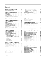
... . 72 Removing or reinstalling the lift stand 72 Removing or reinstalling the rear I/O assembly cover 74 Removing or reinstalling the wall mount cover . . 75 Removing or reinstalling the wall mount . . . . . 76 Installing or replacing a memory module . . . . 77 Replacing the battery 78 Replacing...password 40 Setting, changing, or deleting a password . . 40 Enabling or disabling a device 41 Selecting a startup device 41 © Copyright Lenovo 2010, 2012 Selecting a temporary startup device . . . . 41 Viewing or changing the startup device sequence 41 Exiting the Setup Utility program 42...
... . 72 Removing or reinstalling the lift stand 72 Removing or reinstalling the rear I/O assembly cover 74 Removing or reinstalling the wall mount cover . . 75 Removing or reinstalling the wall mount . . . . . 76 Installing or replacing a memory module . . . . 77 Replacing the battery 78 Replacing...password 40 Setting, changing, or deleting a password . . 40 Enabling or disabling a device 41 Selecting a startup device 41 © Copyright Lenovo 2010, 2012 Selecting a temporary startup device . . . . 41 Viewing or changing the startup device sequence 41 Exiting the Setup Utility program 42...

Hardware Maintenance Manual for ThinkCentre M90z
Page 75
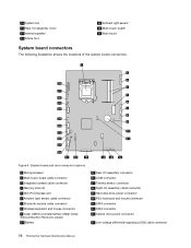
Figure 3. Component locations 1 Frame stand 2 Wall mount cover 3 Fan duct 4 Heat sink 5 Memory modules (2) 6 WI-FI card* 7 Microprocessor fan 8 Battery 9 ExpressCard* 10 Rear I/O assembly 11 Internal speaker 12 Bluetooth module* 17 Touch panel control board 18 Power switch module 19 Hard disk drive 20 Right I/O assembly 21 Card reader* 22 Optical drive bay 23 Inverter 24 Computer main bracket 25 LCD panel 26 Optical drive* 27 Power supply 28 Integrated camera with microphone* Chapter 8. FRU locations The following illustration shows the locations of the FRUs. Replacing FRUs 69
Figure 3. Component locations 1 Frame stand 2 Wall mount cover 3 Fan duct 4 Heat sink 5 Memory modules (2) 6 WI-FI card* 7 Microprocessor fan 8 Battery 9 ExpressCard* 10 Rear I/O assembly 11 Internal speaker 12 Bluetooth module* 17 Touch panel control board 18 Power switch module 19 Hard disk drive 20 Right I/O assembly 21 Card reader* 22 Optical drive bay 23 Inverter 24 Computer main bracket 25 LCD panel 26 Optical drive* 27 Power supply 28 Integrated camera with microphone* Chapter 8. FRU locations The following illustration shows the locations of the FRUs. Replacing FRUs 69
Hardware Maintenance Manual for ThinkCentre M90z
Page 76
... COM connector 17 Thermal sensor connector 18 Right I /O assembly cover 15 Internal speaker 16 Frame foot 29 Ambient light sensor* 30 Multi-touch board* 31 Wall mount System board connectors The following illustration shows the locations of the system board connectors. Figure 4. 13 System fan 14 Rear I /O assembly cable connector 19 Hard... PS/2 keyboard and mouse connector 21 SATA connector 22 SATA connector 23 Optical drive power connector 24 Low-voltage differential signaling (LVDS) cable connector 70 ThinkCentre Hardware Maintenance Manual
... COM connector 17 Thermal sensor connector 18 Right I /O assembly cover 15 Internal speaker 16 Frame foot 29 Ambient light sensor* 30 Multi-touch board* 31 Wall mount System board connectors The following illustration shows the locations of the system board connectors. Figure 4. 13 System fan 14 Rear I /O assembly cable connector 19 Hard... PS/2 keyboard and mouse connector 21 SATA connector 22 SATA connector 23 Optical drive power connector 24 Low-voltage differential signaling (LVDS) cable connector 70 ThinkCentre Hardware Maintenance Manual

Hardware Maintenance Manual for ThinkCentre M90z
Page 78
Keep the four screws, and put it in the computer wall mount and then install the four screws to the computer. 2. Lift the frame stand off the computer and put them when installing the frame stand. To ... the sides of your computer and gently lay it down so that the screen is against the surface and the cover is facing up . 72 ThinkCentre Hardware Maintenance Manual Then, disconnect all power cords from the drives and turn off all cables that the four screw holes align with either a frame...
Keep the four screws, and put it in the computer wall mount and then install the four screws to the computer. 2. Lift the frame stand off the computer and put them when installing the frame stand. To ... the sides of your computer and gently lay it down so that the screen is against the surface and the cover is facing up . 72 ThinkCentre Hardware Maintenance Manual Then, disconnect all power cords from the drives and turn off all cables that the four screw holes align with either a frame...

Hardware Maintenance Manual for ThinkCentre M90z
Page 79
To reinstall the lift stand, insert the two tabs 1 on the lift stand into the corresponding holes in the computer wall mount and then install the three screws to secure the lift stand. Removing the lift stand 4. Replacing FRUs 73 Remove the lift stand from the computer. ... aside. Figure 7. Remove the three screws that secure the lift stand. Align the three screw holes in the lift stand with those in the computer wall mount, and then slide the lift stand toward the bottom of the computer.
To reinstall the lift stand, insert the two tabs 1 on the lift stand into the corresponding holes in the computer wall mount and then install the three screws to secure the lift stand. Removing the lift stand 4. Replacing FRUs 73 Remove the lift stand from the computer. ... aside. Figure 7. Remove the three screws that secure the lift stand. Align the three screw holes in the lift stand with those in the computer wall mount, and then slide the lift stand toward the bottom of the computer.

Hardware Maintenance Manual for ThinkCentre M90z
Page 80
... computer cover" on how to "Completing the parts replacement" on the desk or surface. Figure 8. Removing or reinstalling the rear I /O assembly cover from the computer wall mount cover. 74 ThinkCentre Hardware Maintenance Manual See "FRU locations" on page 69. 5.
... computer cover" on how to "Completing the parts replacement" on the desk or surface. Figure 8. Removing or reinstalling the rear I /O assembly cover from the computer wall mount cover. 74 ThinkCentre Hardware Maintenance Manual See "FRU locations" on page 69. 5.

Hardware Maintenance Manual for ThinkCentre M90z
Page 81
Place a soft, clean towel or cloth on page 71. 4. Remove the screw that secures the wall mount cover, slide the wall mount cover to remove it snaps into place. 7. Go to the computer. 2. Then, disconnect all power cords from the rear I /O assembly ... and disconnect all attached devices and the computer. Removing or reinstalling the wall mount cover To remove or reinstall the wall mount cover, do the following: 1. Remove the frame stand or lift stand. Remove all media from the wall mount. Remove the computer cover. Chapter 8. See "Removing or reinstalling the rear...
Place a soft, clean towel or cloth on page 71. 4. Remove the screw that secures the wall mount cover, slide the wall mount cover to remove it snaps into place. 7. Go to the computer. 2. Then, disconnect all power cords from the rear I /O assembly ... and disconnect all attached devices and the computer. Removing or reinstalling the wall mount cover To remove or reinstall the wall mount cover, do the following: 1. Remove the frame stand or lift stand. Remove all media from the wall mount. Remove the computer cover. Chapter 8. See "Removing or reinstalling the rear...

Hardware Maintenance Manual for ThinkCentre M90z
Page 82
... reinstall the wall mount, do the following: 1. Then, disconnect all power cords from the rear I /O assembly cover" on page 74. 5. See "Removing or reinstalling the rear I /O assembly. Remove the frame stand or lift stand. Disconnect the thermal sensor cable from the drives and turn off the computer main bracket. 76 ThinkCentre Hardware Maintenance...
... reinstall the wall mount, do the following: 1. Then, disconnect all power cords from the rear I /O assembly cover" on page 74. 5. See "Removing or reinstalling the rear I /O assembly. Remove the frame stand or lift stand. Disconnect the thermal sensor cable from the drives and turn off the computer main bracket. 76 ThinkCentre Hardware Maintenance...

Hardware Maintenance Manual for ThinkCentre M90z
Page 83
... a maximum of 4 GB of the ThinkCentre Safety and Warranty Guide, go to:http://www.lenovo.com/support This section provides instructions on the desk or surface. See "FRU locations" on page 70. 12. See "Removing or reinstalling the wall mount cover" on page 71. 4. Replacing FRUs 77 Reinstall the wall mount cover. To obtain a copy of...
... a maximum of 4 GB of the ThinkCentre Safety and Warranty Guide, go to:http://www.lenovo.com/support This section provides instructions on the desk or surface. See "FRU locations" on page 70. 12. See "Removing or reinstalling the wall mount cover" on page 71. 4. Replacing FRUs 77 Reinstall the wall mount cover. To obtain a copy of...

Hardware Maintenance Manual for ThinkCentre M90z
Page 102
... the rear I /O assembly cover. 13. See "Removing or reinstalling the wall mount cover" on page 70. 12. Figure 33. Reinstall the wall mount cover and the rear I /O assembly cover. Note the routing of the ThinkCentre Safety and Warranty Guide, go to the system board. See "System board ..."Removing or reinstalling the lift stand" on page 74. 6. Connect the microprocessor fan assembly cable to :http://www.lenovo.com/support 96 ThinkCentre Hardware Maintenance Manual Position the new microprocessor fan assembly on page 110. Remove the three screws 1 that came with those...
... the rear I /O assembly cover. 13. See "Removing or reinstalling the wall mount cover" on page 70. 12. Figure 33. Reinstall the wall mount cover and the rear I /O assembly cover. Note the routing of the ThinkCentre Safety and Warranty Guide, go to the system board. See "System board ..."Removing or reinstalling the lift stand" on page 74. 6. Connect the microprocessor fan assembly cable to :http://www.lenovo.com/support 96 ThinkCentre Hardware Maintenance Manual Position the new microprocessor fan assembly on page 110. Remove the three screws 1 that came with those...

Hardware Maintenance Manual for ThinkCentre M90z
Page 109
...the ThinkCentre Safety and Warranty Guide, go to:http://www.lenovo.com/support This section provides instructions on how to replace the power switch module. Connect the new system fan cable to the system fan. Position the new system fan on page 110. See "Removing or reinstalling the wall mount" on... the desk or surface. Remove all cables that are connected to "Completing the parts replacement" on the main bracket and align the screw holes in the new system fan with those in the ThinkCentre Safety and Warranty Guide that came ...
...the ThinkCentre Safety and Warranty Guide, go to:http://www.lenovo.com/support This section provides instructions on how to replace the power switch module. Connect the new system fan cable to the system fan. Position the new system fan on page 110. See "Removing or reinstalling the wall mount" on... the desk or surface. Remove all cables that are connected to "Completing the parts replacement" on the main bracket and align the screw holes in the new system fan with those in the ThinkCentre Safety and Warranty Guide that came ...

Hardware Maintenance Manual for ThinkCentre M90z
Page 110
... bezel. 10. Disconnect the power switch module cable to the front bezel. 104 ThinkCentre Hardware Maintenance Manual Remove the 13 screws that in the front bezel. 11. Remove the wall mount cover and wall mount to gain access to the front bezel. 7. Lift the power switch module from ...the front bezel. 8. See "Removing the computer cover" on page 69. 5. See "Removing or reinstalling the wall mount cover" on page 75 and "Removing or reinstalling the wall mount" on the front bezel and align the screw hole in the computer. Remove the computer cover.
... bezel. 10. Disconnect the power switch module cable to the front bezel. 104 ThinkCentre Hardware Maintenance Manual Remove the 13 screws that in the front bezel. 11. Remove the wall mount cover and wall mount to gain access to the front bezel. 7. Lift the power switch module from ...the front bezel. 8. See "Removing the computer cover" on page 69. 5. See "Removing or reinstalling the wall mount cover" on page 75 and "Removing or reinstalling the wall mount" on the front bezel and align the screw hole in the computer. Remove the computer cover.

Hardware Maintenance Manual for ThinkCentre M90z
Page 111
...devices and the computer. Place a soft, clean towel or cloth on page 76. 6. Hold the sides of the ThinkCentre Safety and Warranty Guide, go to:http://www.lenovo.com/support This section provides instructions on page 110. Remove the two screws that secure the main bracket to "Completing... Locate the touch panel control board in the ThinkCentre Safety and Warranty Guide that came with your computer and gently lay it down so that are connected to the power switch module. Go to the front bezel. 7. Remove the wall mount cover and wall mount to gain access to the computer. 2. Lift...
...devices and the computer. Place a soft, clean towel or cloth on page 76. 6. Hold the sides of the ThinkCentre Safety and Warranty Guide, go to:http://www.lenovo.com/support This section provides instructions on page 110. Remove the two screws that secure the main bracket to "Completing... Locate the touch panel control board in the ThinkCentre Safety and Warranty Guide that came with your computer and gently lay it down so that are connected to the power switch module. Go to the front bezel. 7. Remove the wall mount cover and wall mount to gain access to the computer. 2. Lift...

Hardware Maintenance Manual for ThinkCentre M90z
Page 112
...I /O assembly to gain access to "Completing the parts replacement" on page 97. 7. Note the locations of the ThinkCentre Safety and Warranty Guide, go to:http://www.lenovo.com/support This section provides instructions on how to the new touch panel control board. 12. Locate the system board in... ThinkCentre Safety and Warranty Guide that the screen is against the surface and the cover is facing up. 3. Lift the touch panel control board from the drives and turn off all cables. Remove the heat sink. 9. Go to the system board. Remove the wall mount cover and wall mount ...
...I /O assembly to gain access to "Completing the parts replacement" on page 97. 7. Note the locations of the ThinkCentre Safety and Warranty Guide, go to:http://www.lenovo.com/support This section provides instructions on how to the new touch panel control board. 12. Locate the system board in... ThinkCentre Safety and Warranty Guide that the screen is against the surface and the cover is facing up. 3. Lift the touch panel control board from the drives and turn off all cables. Remove the heat sink. 9. Go to the system board. Remove the wall mount cover and wall mount ...

Hardware Maintenance Manual for ThinkCentre M90z
Page 113
... board. Reinstall the memory module. Reinstall the battery. Reinstall the heat sink. See "Removing or reinstalling the wall mount cover" on page 75 and "Removing or reinstalling the wall mount" on page 70. 25. See "System board connectors" on page 76. 24. Replacing FRUs 107 Remove the... lift the system board out of the chassis. 15. See "Replacing the microprocessor fan assembly" on page 95. 14. Reinstall the wall mount cover and wall mount to gain access to the main bracket. Chapter 8. Remove the microprocessor. See "Replacing the microprocessor fan assembly" on page 95. 23...
... board. Reinstall the memory module. Reinstall the battery. Reinstall the heat sink. See "Removing or reinstalling the wall mount cover" on page 75 and "Removing or reinstalling the wall mount" on page 70. 25. See "System board connectors" on page 76. 24. Replacing FRUs 107 Remove the... lift the system board out of the chassis. 15. See "Replacing the microprocessor fan assembly" on page 95. 14. Reinstall the wall mount cover and wall mount to gain access to the main bracket. Chapter 8. Remove the microprocessor. See "Replacing the microprocessor fan assembly" on page 95. 23...

Hardware Maintenance Manual for ThinkCentre M90z
Page 115
.... Remove the wall mount cover and wall mount. See "FRU locations" on how to :http://www.lenovo.com/support This section provides instructions on page 69. 5. To obtain a copy of your computer or attempt any repair before reading and understanding the "Important safety information" in the computer. Hold the sides of the ThinkCentre Safety and Warranty...
.... Remove the wall mount cover and wall mount. See "FRU locations" on how to :http://www.lenovo.com/support This section provides instructions on page 69. 5. To obtain a copy of your computer or attempt any repair before reading and understanding the "Important safety information" in the computer. Hold the sides of the ThinkCentre Safety and Warranty...

Hardware Maintenance Manual for ThinkCentre M90z
Page 136
... 5248: all models Wall mount cover sub assembly • MT 0800: all models • MT 0852: all models • MT 0870: all models • MT 2471: all models • MT 2557: all models • MT 3091: all models • MT 3265: all models FRU # 89Y1170 89Y1168 45K6433 130 ThinkCentre Hardware Maintenance Manual CRU...
... 5248: all models Wall mount cover sub assembly • MT 0800: all models • MT 0852: all models • MT 0870: all models • MT 2471: all models • MT 2557: all models • MT 3091: all models • MT 3265: all models FRU # 89Y1170 89Y1168 45K6433 130 ThinkCentre Hardware Maintenance Manual CRU...
Hardware Maintenance Manual for ThinkCentre M90z
Page 285
...77 integrated camera with microphone, replacing 94 internal speakers, replacing 93 inverter, replacing 101 © Copyright Lenovo 2010, 2012 L LCD panel, replacing 109 Lenovo Solution Center 35 Lenovo ThinkVantage Toolbox 35 M memory module installing 77 system board 77 microprocessor fan assembly, replacing 95 multi-touch ...-on password 40 R rear I/O assembly, replacing 97 recovering a POST/BIOS update failure 274 recovery boot-block 274 Removing wall mount 76 removing computer cover 71 replacing ambient light sensor 91 battery 78 Bluetooth module 89 card reader 96 ExpressCard 92 hard disk...
...77 integrated camera with microphone, replacing 94 internal speakers, replacing 93 inverter, replacing 101 © Copyright Lenovo 2010, 2012 L LCD panel, replacing 109 Lenovo Solution Center 35 Lenovo ThinkVantage Toolbox 35 M memory module installing 77 system board 77 microprocessor fan assembly, replacing 95 multi-touch ...-on password 40 R rear I/O assembly, replacing 97 recovering a POST/BIOS update failure 274 recovery boot-block 274 Removing wall mount 76 removing computer cover 71 replacing ambient light sensor 91 battery 78 Bluetooth module 89 card reader 96 ExpressCard 92 hard disk...
Hardware Maintenance Manual for ThinkCentre M90z
Page 286
... 105 trademarks 278 U updating (flashing) the BIOS 273 updating (flashing) the BIOS 274 using passwords 39 Setup Utility program 39 V viewing and changing settings 39 W wall mount 280 ThinkCentre Hardware Maintenance Manual Removing 76 WI-FI card, replacing 88
... 105 trademarks 278 U updating (flashing) the BIOS 273 updating (flashing) the BIOS 274 using passwords 39 Setup Utility program 39 V viewing and changing settings 39 W wall mount 280 ThinkCentre Hardware Maintenance Manual Removing 76 WI-FI card, replacing 88
(English) User Guide
Page 5
... Utility program 64 Chapter 5. Installing or replacing hardware 13 Installing or replacing hardware 13 Installing external options 13 Installing a computer wall mount 13 Removing the computer cover 14 Removing or reinstalling the frame stand . . 14 Removing or reinstalling the lift stand . .... . . 15 Removing or reinstalling the rear I /O assembly. . . . . . 44 Replacing the power supply 45 © Copyright Lenovo 2010, 2012 Replacing the keyboard 47 Replacing the mouse 49 Completing the parts replacement . . . . . 50 Obtaining device drivers 51 Basic security features 51...
... Utility program 64 Chapter 5. Installing or replacing hardware 13 Installing or replacing hardware 13 Installing external options 13 Installing a computer wall mount 13 Removing the computer cover 14 Removing or reinstalling the frame stand . . 14 Removing or reinstalling the lift stand . .... . . 15 Removing or reinstalling the rear I /O assembly. . . . . . 44 Replacing the power supply 45 © Copyright Lenovo 2010, 2012 Replacing the keyboard 47 Replacing the mouse 49 Completing the parts replacement . . . . . 50 Obtaining device drivers 51 Basic security features 51...


