(English) Rescue and Recovery 4.3 Deployment Guide
Page 14
... 7 v Memory: 1 GB - however, the user will run the Rescue and Recovery setup package. v Supported Ethernet card. v User must meet or exceed the following requirements: Installation requirements: 2.4 GB of 800 x 600 and 24-bit ...one application in the Rescue and Recovery environment. In shared memory configurations, the BIOS setting for non-Lenovo computers Installation on your hard drive. Note: When installing this package, refer to the readme file ...before you have administrative privileges. v VGA-compatible video that you begin to install the Rescue and Recovery program.
... 7 v Memory: 1 GB - however, the user will run the Rescue and Recovery setup package. v Supported Ethernet card. v User must meet or exceed the following requirements: Installation requirements: 2.4 GB of 800 x 600 and 24-bit ...one application in the Rescue and Recovery environment. In shared memory configurations, the BIOS setting for non-Lenovo computers Installation on your hard drive. Note: When installing this package, refer to the readme file ...before you have administrative privileges. v VGA-compatible video that you begin to install the Rescue and Recovery program.
(English) Rescue and Recovery 4.5 Deployment Guide
Page 10
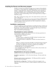
... 600 and 24-bit color. • Supported Ethernet card. • User must be unable to a specified location. Click ThinkVantage and then click the Rescue and Recovery icon to the Lenovo Web site at http://support.lenovo.com. The default extract location is required. Installation requirements ... the locations for unpacking the setup files. In shared memory configurations, the BIOS setting for the system cache. • VGA-compatible video that supports a resolution of the software installed. You can obtain the setup package from the command line using the /a parameter: setup...
... 600 and 24-bit color. • Supported Ethernet card. • User must be unable to a specified location. Click ThinkVantage and then click the Rescue and Recovery icon to the Lenovo Web site at http://support.lenovo.com. The default extract location is required. Installation requirements ... the locations for unpacking the setup files. In shared memory configurations, the BIOS setting for the system cache. • VGA-compatible video that supports a resolution of the software installed. You can obtain the setup package from the command line using the /a parameter: setup...

Hardware Maintenance Manual
Page 67
... update procedures" on page 606 2. System board 1. Video card, if installed 2. System board Chapter 7. Symptom-to-FRU Index 61 Video card, if installed 3. Run Setup and re-test 2. System board 1. Video card, if installed 2. Video Ram 2. Video drivers update 3. System board 1. Flash the system. Video card, if installed 2. System board 1. Video card, if installed 4. Video card, if installed 2. System board System board System board...
... update procedures" on page 606 2. System board 1. Video card, if installed 2. System board Chapter 7. Symptom-to-FRU Index 61 Video card, if installed 3. Run Setup and re-test 2. System board 1. Video card, if installed 2. Video Ram 2. Video drivers update 3. System board 1. Flash the system. Video card, if installed 2. System board 1. Video card, if installed 4. Video card, if installed 2. System board System board System board...
Hardware Maintenance Manual
Page 68
...F3 to "Undetermined problems" on page 82 1. Flash the system and re-test. Flash the system and re-test. Diskette drive Cable 2. Video card, if installed 2. Replace the component called out in warning statement 4. Go to review the log file 2. Replace component under test 1. System ...board 1. Diskette drive 3. Press F3 to "Undetermined problems" on page 82 2. System board Information only Re-start the test, if necessary 1. Video card, if installed 2. System board Information only Re-start the test, if necessary 1. Re-start the test to reset the log file 1. Re...
...F3 to "Undetermined problems" on page 82 1. Flash the system and re-test. Flash the system and re-test. Diskette drive Cable 2. Video card, if installed 2. Replace the component called out in warning statement 4. Go to review the log file 2. Replace component under test 1. System ...board 1. Diskette drive 3. Press F3 to "Undetermined problems" on page 82 2. System board Information only Re-start the test, if necessary 1. Video card, if installed 2. System board Information only Re-start the test, if necessary 1. Re-start the test to reset the log file 1. Re...

Hardware Maintenance Manual
Page 82
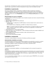
...Monitor 4. CD-ROM drive 4. Hard Disk drive (IDE) 5. Remove the Hi-Capacity Cartridge Drive and re-test the system 1. Keyboard 2. SCSI adapter card 6. Reseat the hard disk drive cable 4. System board 76 Hardware Maintenance Manual System board No action 1. Hard Disk Drive Cable 2. Diagnostic Error Code ... No action 1. Check power supply voltages 3. System board No action 1. Check and test Keyboard 3. Cable 3. Check and test mouse 3. Video card 5. System board No action No action 1. Check power supply voltages 3. Check power supply voltages 3. Mouse 2.
...Monitor 4. CD-ROM drive 4. Hard Disk drive (IDE) 5. Remove the Hi-Capacity Cartridge Drive and re-test the system 1. Keyboard 2. SCSI adapter card 6. Reseat the hard disk drive cable 4. System board 76 Hardware Maintenance Manual System board No action 1. Hard Disk Drive Cable 2. Diagnostic Error Code ... No action 1. Check power supply voltages 3. System board No action 1. Check and test Keyboard 3. Cable 3. Check and test mouse 3. Video card 5. System board No action No action 1. Check power supply voltages 3. Check power supply voltages 3. Mouse 2.
Hardware Maintenance Manual
Page 84
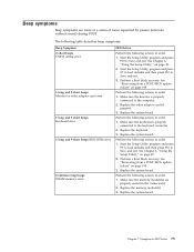
...during POST. Start the Setup Utility program and press F7 to load defaults and then press F10 to Save and exit. Replace the video adapter card (if present). 3. Replace the system board. 78 Hardware Maintenance Manual Start the Setup Utility program and press F10 to Save and ...the computer. 2. The following tables describes beep symptoms. Beep Symptom 2 short beeps CMOS setting error 1 long and 2 short beeps Monitor or video adapter card error 1 long and 3 short beeps Keyboard error 1 long and 9 short beeps BIOS ROM error Continuos long beeps DRAM memory error FRU/Action...
...during POST. Start the Setup Utility program and press F7 to load defaults and then press F10 to Save and exit. Replace the video adapter card (if present). 3. Replace the system board. 78 Hardware Maintenance Manual Start the Setup Utility program and press F10 to Save and ...the computer. 2. The following tables describes beep symptoms. Beep Symptom 2 short beeps CMOS setting error 1 long and 2 short beeps Monitor or video adapter card error 1 long and 3 short beeps Keyboard error 1 long and 9 short beeps BIOS ROM error Continuos long beeps DRAM memory error FRU/Action...
Hardware Maintenance Manual
Page 87
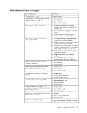
... no interrupt or I/O address conflicts 6. System Board Diskette drive in the first 3.5-inch diskette drive. 1. System Board 3. Riser card, if installed Computer will not RPL from left to enable Wake on page 55. 1. Check power supply and signal cable connections to... is enabled for RPL 3. System Board ″Insert a Diskette″ icon appears with an otherwise blank display. 1. System Board 2. Video adapter (if present) 3. Miscellaneous error messages Message/Symptom FRU/Action Changing display colors Display/Monitor Computer will not perform a Wake On LAN...
... no interrupt or I/O address conflicts 6. System Board Diskette drive in the first 3.5-inch diskette drive. 1. System Board 3. Riser card, if installed Computer will not RPL from left to enable Wake on page 55. 1. Check power supply and signal cable connections to... is enabled for RPL 3. System Board ″Insert a Diskette″ icon appears with an otherwise blank display. 1. System Board 2. Video adapter (if present) 3. Miscellaneous error messages Message/Symptom FRU/Action Changing display colors Display/Monitor Computer will not perform a Wake On LAN...

Hardware Maintenance Manual
Page 64
Run Setup and re-test 2. CMOS Battery 2. System board 1. Video card if installed 2. Video card if installed 3. Video card if installed 2. Video drivers update 3. Video cable 2. Flash the system. System board 1. Video Ram 2. Video card if installed 2. Monitor 3. Video card if installed 2. System board Flash the system. See "Flash update procedures" on page 197 2. Video card if installed 2. System board 1. See "Flash update procedures" on page...
Run Setup and re-test 2. CMOS Battery 2. System board 1. Video card if installed 2. Video card if installed 3. Video card if installed 2. Video drivers update 3. Video cable 2. Flash the system. System board 1. Video Ram 2. Video card if installed 2. Monitor 3. Video card if installed 2. System board Flash the system. See "Flash update procedures" on page 197 2. Video card if installed 2. System board 1. See "Flash update procedures" on page...

Hardware Maintenance Manual
Page 65
... called out make sure it is connected and/or enabled. Diskette drive Cable 2. Press F3 to -FRU Index 59 System board 1. Video card if installed 2. System board Information only Re-start the test if necessary 1. Replace the component under function test 1. Replace component under ...test 1. If a component is connected and/or enabled. Flash the system and re-test. Video card if installed 2. Video card if installed 2. Diskette drive 3. System board Information only Re-start the test if necessary 1. Diagnostic Error Code 005-036-XXX...
... called out make sure it is connected and/or enabled. Diskette drive Cable 2. Press F3 to -FRU Index 59 System board 1. Video card if installed 2. System board Information only Re-start the test if necessary 1. Replace the component under function test 1. Replace component under ...test 1. If a component is connected and/or enabled. Flash the system and re-test. Video card if installed 2. Video card if installed 2. Diskette drive 3. System board Information only Re-start the test if necessary 1. Diagnostic Error Code 005-036-XXX...

Hardware Maintenance Manual
Page 79
... 4. Hard Disk drive (SCSI) 5. Keyboard 2. Check power supply voltages 3. Hard Disk drive (IDE) 5. Reseat the hard disk drive cable 4. Cable 3. Monitor 4. SCSI adapter card 6. Check and test Keyboard 3. Video card 5. Check power supply voltages 3. System board No action Remove the Joystick and re-test the system No action 1. Symptom-to enable DDC 2. Hard...
... 4. Hard Disk drive (SCSI) 5. Keyboard 2. Check power supply voltages 3. Hard Disk drive (IDE) 5. Reseat the hard disk drive cable 4. Cable 3. Monitor 4. SCSI adapter card 6. Check and test Keyboard 3. Video card 5. Check power supply voltages 3. System board No action Remove the Joystick and re-test the system No action 1. Symptom-to enable DDC 2. Hard...
Hardware Maintenance Manual
Page 81
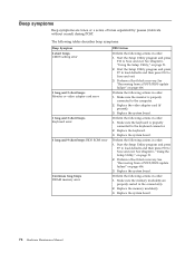
...in order. 1. The following table describes beep symptoms. Beep Symptom 2 short beeps CMOS setting error 1 long and 2 short beeps Monitor or video adapter card error 1 long and 3 short beeps Keyboard error 1 long and 9 short beeps BIOS ROM error Continuos long beeps DRAM memory error FRU/... Make sure the monitor is properly connected to the computer. 2. See Chapter 6, "Using the Setup Utility," on page 198. 3. Replace the video adapter card (if present). 3. Make sure the memory module(s) are tones or a series of tones separated by pauses (intervals without sound) during POST. ...
...in order. 1. The following table describes beep symptoms. Beep Symptom 2 short beeps CMOS setting error 1 long and 2 short beeps Monitor or video adapter card error 1 long and 3 short beeps Keyboard error 1 long and 9 short beeps BIOS ROM error Continuos long beeps DRAM memory error FRU/... Make sure the monitor is properly connected to the computer. 2. See Chapter 6, "Using the Setup Utility," on page 198. 3. Replace the video adapter card (if present). 3. Make sure the memory module(s) are tones or a series of tones separated by pauses (intervals without sound) during POST. ...

Hardware Maintenance Manual
Page 84
... sequence as first device or first device after diskette 2. Diskette Drive Cable 1. Network Adapter 1. Diskette Drive 2. Run the Memory tests 2. Video adapter (if present) 3. Flashing cursor with a known-good diagnostics diskette in -use light remains on page 53. Ensure that the operating ...system settings are set to network adapter 2. System Board 1. Riser card if installed 1. System Board 3. Intensity or color varies from server Computer will not power-off. Diskette drive in the first 3.5-inch ...
... sequence as first device or first device after diskette 2. Diskette Drive Cable 1. Network Adapter 1. Diskette Drive 2. Run the Memory tests 2. Video adapter (if present) 3. Flashing cursor with a known-good diagnostics diskette in -use light remains on page 53. Ensure that the operating ...system settings are set to network adapter 2. System Board 1. Riser card if installed 1. System Board 3. Intensity or color varies from server Computer will not power-off. Diskette drive in the first 3.5-inch ...


