User Manual
Page 5
...3 Connecting your computer 4 Turning on the system board . . . . . 25 Installing memory 29 Installing PCI adapters 30 Installing internal drives 31 Drive specifications 32 Installing a drive in bay...) BIOS from the Setup Utility program . . . . . 52 Chapter 6. Troubleshooting and diagnostics 55 © Lenovo 2006, 2007. Recovering software . . . . 41 Creating and using the Product Recovery disc . . . 41... . . . . 13 Features 13 Available options 16 Specifications 17 Supported operating positions 18 Tools required 18 Handling static-sensitive devices 18 Installing ...
...3 Connecting your computer 4 Turning on the system board . . . . . 25 Installing memory 29 Installing PCI adapters 30 Installing internal drives 31 Drive specifications 32 Installing a drive in bay...) BIOS from the Setup Utility program . . . . . 52 Chapter 6. Troubleshooting and diagnostics 55 © Lenovo 2006, 2007. Recovering software . . . . 41 Creating and using the Product Recovery disc . . . 41... . . . . 13 Features 13 Available options 16 Specifications 17 Supported operating positions 18 Tools required 18 Handling static-sensitive devices 18 Installing ...
User Manual
Page 34
...® 4 processor with HyperThreading Technology v Intel Pentium D processor v Intel Celeron® D processor v Internal cache (size varies by model type) Memory v Support for two double data rate 2 (DDR2) dual inline memory modules (DIMMs) v 4 Mb flash memory for system programs Internal drives v Diskette drive (some models) v Parallel Advanced Technology Attachment (PATA) internal hard disk (some models...
...® 4 processor with HyperThreading Technology v Intel Pentium D processor v Intel Celeron® D processor v Internal cache (size varies by model type) Memory v Support for two double data rate 2 (DDR2) dual inline memory modules (DIMMs) v 4 Mb flash memory for system programs Internal drives v Diskette drive (some models) v Parallel Advanced Technology Attachment (PATA) internal hard disk (some models...

User Manual
Page 38
... must position your computer in your movement. See the instructions that come with any exposed circuitry. Handle adapters and memory modules by the edges. v Prevent others from touching components. 18 User Guide Supported operating positions Attention: Do not block the air vents on the top of the computer with the option. When...
... must position your computer in your movement. See the instructions that come with any exposed circuitry. Handle adapters and memory modules by the edges. v Prevent others from touching components. 18 User Guide Supported operating positions Attention: Do not block the air vents on the top of the computer with the option. When...
User Manual
Page 73
...begins. 3. Portions © IBM Corp. 2005. 53 They include the power-on the Lenovo Web site at http://www.lenovo.com/support on the computer. You can download a self starting your computer. Lenovo might make changes and enhancements to create a system-program-update (flash) diskette or an...is included with the update files. Your computer system board has a module called electrically erasable programmable read-only memory (EEPROM, also referred to complete the update. © Lenovo 2006, 2007. Follow the instructions on the screen to as an .iso image) of software into the...
...begins. 3. Portions © IBM Corp. 2005. 53 They include the power-on the Lenovo Web site at http://www.lenovo.com/support on the computer. You can download a self starting your computer. Lenovo might make changes and enhancements to create a system-program-update (flash) diskette or an...is included with the update files. Your computer system board has a module called electrically erasable programmable read-only memory (EEPROM, also referred to complete the update. © Lenovo 2006, 2007. Follow the instructions on the screen to as an .iso image) of software into the...

User Manual
Page 85
...four telephone numbers (n=0-3) stored in Command Mode. Your modem is in the modem non-volatile memory. To make the command line more readable, spaces can be typed in bold text. Do... incoming call. Commands are not echoed Commands are accepted by the modem while it is not supported for manually programming your modem from a PC running communication software or any other terminal devices. ...for Australia, New Zealand, Norway, and South Africa. Command) Force modem on-hook (hang up) © Lenovo 2006, 2007. All commands sent to the modem must begin with AT and end with ENTER. 0 - ...
...four telephone numbers (n=0-3) stored in Command Mode. Your modem is in the modem non-volatile memory. To make the command line more readable, spaces can be typed in bold text. Do... incoming call. Commands are not echoed Commands are accepted by the modem while it is not supported for manually programming your modem from a PC running communication software or any other terminal devices. ...for Australia, New Zealand, Norway, and South Africa. Command) Force modem on-hook (hang up) © Lenovo 2006, 2007. All commands sent to the modem must begin with AT and end with ENTER. 0 - ...

User Manual
Page 86
... X4 Z_ Z0 Z1 66 User Guide Function Force modem off-hook (make busy) Note: H1 command is not supported for Italy Display product-identification code Factory ROM checksum test Internal memory test Firmware ID Reserved ID Low speaker volume Low speaker volume Medium speaker volume High speaker volume Internal speaker off...
... X4 Z_ Z0 Z1 66 User Guide Function Force modem off-hook (make busy) Note: H1 command is not supported for Italy Display product-identification code Factory ROM checksum test Internal memory test Firmware ID Reserved ID Low speaker volume Low speaker volume Medium speaker volume High speaker volume Internal speaker off...
User Manual
Page 95
...computer 10 connecting drives 33 connector description 21 connectors front 19 rear 20 cover removing 22 replacing 39 Customer Replacement Units (CRUs) 62 Customer Support Center 63 D device drivers 21 diagnostic CD image 10, 57, 58 diskettes 10, 57, 58, 59 PC-Doctor for DOS 56... 59 diagnostic CD image creating 57 running 58 diagnostic diskettes creating 57 running 58 drives bays 32 © Lenovo 2006, 2007. drives (continued) internal 31 specifications 32 dual inline memory modules (DIMMs) 29 E environment, operating 17 Ethernet 14 Ethernet connector 21 exiting, Setup Utility 52 expansion ...
...computer 10 connecting drives 33 connector description 21 connectors front 19 rear 20 cover removing 22 replacing 39 Customer Replacement Units (CRUs) 62 Customer Support Center 63 D device drivers 21 diagnostic CD image 10, 57, 58 diskettes 10, 57, 58, 59 PC-Doctor for DOS 56... 59 diagnostic CD image creating 57 running 58 diagnostic diskettes creating 57 running 58 drives bays 32 © Lenovo 2006, 2007. drives (continued) internal 31 specifications 32 dual inline memory modules (DIMMs) 29 E environment, operating 17 Ethernet 14 Ethernet connector 21 exiting, Setup Utility 52 expansion ...
User Manual
Page 96
... deleting 50 user 50 passwords considerations 49 PCI adapter 30 physical specifications 17 power Advanced Configuration and Power Interface (ACPI) support 15 Advanced Power Management support 15 features 15 turning off computer 11 turning on 10 power-on self-test (POST) 53 R removing the cover ...10 system board components, accessing 24 connectors 26, 27 identifying parts 25 location 26, 27, 28 76 User Guide system board (continued) memory 16, 29 system management 14 system programs 53 T ThinkVantage Productivity Center 61 trademarks 74 troubleshooting 55 U updating (flashing) BIOS 53 antivirus...
... deleting 50 user 50 passwords considerations 49 PCI adapter 30 physical specifications 17 power Advanced Configuration and Power Interface (ACPI) support 15 Advanced Power Management support 15 features 15 turning off computer 11 turning on 10 power-on self-test (POST) 53 R removing the cover ...10 system board components, accessing 24 connectors 26, 27 identifying parts 25 location 26, 27, 28 76 User Guide system board (continued) memory 16, 29 system management 14 system programs 53 T ThinkVantage Productivity Center 61 trademarks 74 troubleshooting 55 U updating (flashing) BIOS 53 antivirus...
(English) Rescue and Recovery 4.3 Deployment Guide
Page 14
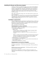
... that is posted on the Lenovo Web page at: http://www.lenovo.com/support/site.wss/document.do?lndocid=MIGR-4Q2QAK The Readme file contains up-to-the-minute information on non-Lenovo computers have the latest version of non-shared memory is not supported on the factory pre-loads ...for installing the Rescue and Recovery package on your hard drive. In non-shared memory configurations, 120 MB of the software installed. v Supported Ethernet card. To obtain...
... that is posted on the Lenovo Web page at: http://www.lenovo.com/support/site.wss/document.do?lndocid=MIGR-4Q2QAK The Readme file contains up-to-the-minute information on non-Lenovo computers have the latest version of non-shared memory is not supported on the factory pre-loads ...for installing the Rescue and Recovery package on your hard drive. In non-shared memory configurations, 120 MB of the software installed. v Supported Ethernet card. To obtain...
(English) Rescue and Recovery 4.3 Deployment Guide
Page 15
... the device manufacturer documentation for instructions to add support for system-specific network drivers. Network device drivers included in Microsoft Windows operating system and are independent of 800 x 600 and 24-bit color v Video memory: - For additional information see the Lenovo Web site at: http://www.lenovo.com/thinkvantage Network adapters for boot-ability...
... the device manufacturer documentation for instructions to add support for system-specific network drivers. Network device drivers included in Microsoft Windows operating system and are independent of 800 x 600 and 24-bit color v Video memory: - For additional information see the Lenovo Web site at: http://www.lenovo.com/thinkvantage Network adapters for boot-ability...
(English) Rescue and Recovery 4.5 Deployment Guide
Page 10
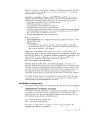
... - the readme file. The Readme file contains up-to-the-minute information on the command line to the Lenovo Web site at http://support.lenovo.com. Requirements for customization. In non-shared memory configurations, 120 MB of the software installed. Installation components This section contains installation components of the Rescue and Recovery program, go...
... - the readme file. The Readme file contains up-to-the-minute information on the command line to the Lenovo Web site at http://support.lenovo.com. Requirements for customization. In non-shared memory configurations, 120 MB of the software installed. Installation components This section contains installation components of the Rescue and Recovery program, go...

Hardware Maintenance Manual
Page 95
Identifying parts on the system board The machine types supported by this maintenance manual include several different system boards. Replacing FRUs (desktop computers) 89 Machine types 8013, 8716, 8976, 8986, 9266, 9282, 9374, 9384, 9646, and 9647 1 Microprocessor fan connector 2 Microprocessor and heat sink 3 Memory connector 1 4 Memory connector 2 5 Clear CMOS/Recovery jumper 6 Power connector...
Identifying parts on the system board The machine types supported by this maintenance manual include several different system boards. Replacing FRUs (desktop computers) 89 Machine types 8013, 8716, 8976, 8986, 9266, 9282, 9374, 9384, 9646, and 9647 1 Microprocessor fan connector 2 Microprocessor and heat sink 3 Memory connector 1 4 Memory connector 2 5 Clear CMOS/Recovery jumper 6 Power connector...

Hardware Maintenance Manual
Page 136
Locate the appropriate machine type in the computer. 1 Heat sink and fan assembly 2 Microprocessor 3 Memory modules 4 Optical drive 5 Diskette drive 6 Bezel 7 Power switch/LED assembly 8 Internal speaker 9 Front audio/USB assembly 10 Hard disk drive 11 System board 12 System fan 13 Power supply Identifying parts on the system board The machine types supported by this maintenance manual include several different system boards. Locations The following illustration will help you locate the major FRUs in one of the following sections. 130 Hardware Maintenance Manual
Locate the appropriate machine type in the computer. 1 Heat sink and fan assembly 2 Microprocessor 3 Memory modules 4 Optical drive 5 Diskette drive 6 Bezel 7 Power switch/LED assembly 8 Internal speaker 9 Front audio/USB assembly 10 Hard disk drive 11 System board 12 System fan 13 Power supply Identifying parts on the system board The machine types supported by this maintenance manual include several different system boards. Locations The following illustration will help you locate the major FRUs in one of the following sections. 130 Hardware Maintenance Manual

(Korean) User guide
Page 77
M ANCzTOY. LX R v VB |b E#N //OB RA.~n h~TOY. D;MG 8: W 3$; 8 E* /fR fl!B Setup Utility ANW%; kX 3mUOY. S '6Y G`GB OCG W:. BIOSB Y% RA.~n h~G mIn& D;M Oe~n! GP C 9 8OB f}! C:[ ANW% gk C:[ ANW%: D;M! ;eH RA.~nG b; C!C w%L. & 6 e C:[ ANW% w%L. h~TOY. B POST(Power-On Self-Test), BIOS(Basic Input/Output System) ZeM Setup Utility ANW%L wTKOY. POSTB D;MG |x; D;MG C:[ 8e!B EEPROM(Electrically Erasable Programmable Read-Only Memory, Om C!C ^p.) pbL V@OY. L e!-B POST/BIOS w%L.! |Q $8 W POST/BIOS w%L. gkR v V@OY. ; p:O; C:[ ANW%! gkO) D;M& C[OE* n5
M ANCzTOY. LX R v VB |b E#N //OB RA.~n h~TOY. D;MG 8: W 3$; 8 E* /fR fl!B Setup Utility ANW%; kX 3mUOY. S '6Y G`GB OCG W:. BIOSB Y% RA.~n h~G mIn& D;M Oe~n! GP C 9 8OB f}! C:[ ANW% gk C:[ ANW%: D;M! ;eH RA.~nG b; C!C w%L. & 6 e C:[ ANW% w%L. h~TOY. B POST(Power-On Self-Test), BIOS(Basic Input/Output System) ZeM Setup Utility ANW%L wTKOY. POSTB D;MG |x; D;MG C:[ 8e!B EEPROM(Electrically Erasable Programmable Read-Only Memory, Om C!C ^p.) pbL V@OY. L e!-B POST/BIOS w%L.! |Q $8 W POST/BIOS w%L. gkR v V@OY. ; p:O; C:[ ANW%! gkO) D;M& C[OE* n5

(Korean) User guide
Page 93
pg mInB k.Z GB R.ZN TBR v Vv8 k.ZM R.Z& %kO) TBR vB x@OY. v? NDKOY. mIn& Pb 15O mIn gL! AT mIn Y= WLmG b; 3$*: pN =: mInB p)L mIn pe! VB ?H! p)! |[GB pg mInB ATN C[Gg ENTERN >aGn_ UOY. JdQ DsLM& }+Q fl, DsLM *: 08N #VKOY. 9: ATH [ENTER] b; mInB kE R A.~n& G`OB PC GB W \G MLN e!NNM p)8N |[KOY. NO A. gkZ! mI n! V@OY. pTR v V@OY. x#& -/ |,aL Gb |nv p): Z?{8N mIn pe sB! v?8N ANW!VOB% JdQ mIn& &xUOY. xi; p) mIn L NO!-B p);
pg mInB k.Z GB R.ZN TBR v Vv8 k.ZM R.Z& %kO) TBR vB x@OY. v? NDKOY. mIn& Pb 15O mIn gL! AT mIn Y= WLmG b; 3$*: pN =: mInB p)L mIn pe! VB ?H! p)! |[GB pg mInB ATN C[Gg ENTERN >aGn_ UOY. JdQ DsLM& }+Q fl, DsLM *: 08N #VKOY. 9: ATH [ENTER] b; mInB kE R A.~n& G`OB PC GB W \G MLN e!NNM p)8N |[KOY. NO A. gkZ! mI n! V@OY. pTR v V@OY. x#& -/ |,aL Gb |nv p): Z?{8N mIn pe sB! v?8N ANW!VOB% JdQ mIn& &xUOY. xi; p) mIn L NO!-B p);

(Korean) User guide
Page 94
... dialing. Command) Force modem on-hook (hang up) Force modem off-hook (make busy) Note: H1 command is not supported for Italy Display product-identification code Factory ROM checksum test Internal memory test Firmware ID Reserved ID Low speaker volume Low speaker volume Medium speaker volume High speaker volume Internal speaker off...
... dialing. Command) Force modem on-hook (hang up) Force modem off-hook (make busy) Note: H1 command is not supported for Italy Display product-identification code Factory ROM checksum test Internal memory test Firmware ID Reserved ID Low speaker volume Low speaker volume Medium speaker volume High speaker volume Internal speaker off...

Hardware Maintenance Manual
Page 203
..., the VPD must be updated. To update the VPD, see "Flash update procedures." Lenovo Customer Support Center 3. The computer is unusable until the password is activated. Lenovo support web site: http://www.lenovo.com/support/ 2. For more information about passwords, see "Using passwords" on the system board....very similar to a power-on password and denies access to obtain the latest level of BIOS installed in the nonvolatile memory on page 49. Start the Setup Utility. - Additional Service Information This chapter provides additional information that the service representative...
..., the VPD must be updated. To update the VPD, see "Flash update procedures." Lenovo Customer Support Center 3. The computer is unusable until the password is activated. Lenovo support web site: http://www.lenovo.com/support/ 2. For more information about passwords, see "Using passwords" on the system board....very similar to a power-on password and denies access to obtain the latest level of BIOS installed in the nonvolatile memory on page 49. Start the Setup Utility. - Additional Service Information This chapter provides additional information that the service representative...


