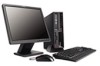
User Manual
Page 5
... on the system board . . . . . 25 Installing memory 29 Installing PCI adapters 30 Installing internal drives 31 Drive specifications 32 Installing a drive in bay 1 33 Installing a diskette drive in the startup sequence . . 47 Solving recovery problems 47 Chapter 5. Recovering software . . . . ...compliance statement xiii Power supply statement xiii Products with television tuner options installed . . Troubleshooting and diagnostics 55 © Lenovo 2006, 2007. Arranging your antivirus software 11 Shutting down the computer 11 Chapter 3. iii Using the Setup Utility ....
... on the system board . . . . . 25 Installing memory 29 Installing PCI adapters 30 Installing internal drives 31 Drive specifications 32 Installing a drive in bay 1 33 Installing a diskette drive in the startup sequence . . 47 Solving recovery problems 47 Chapter 5. Recovering software . . . . ...compliance statement xiii Power supply statement xiii Products with television tuner options installed . . Troubleshooting and diagnostics 55 © Lenovo 2006, 2007. Arranging your antivirus software 11 Shutting down the computer 11 Chapter 3. iii Using the Setup Utility ....
User Manual
Page 13
... or other damage might occur. Do not place any equipment that fall into your keyboard can damage the monitor and data on the hard disk drive. v Connect and disconnect cables as an electric fan, radio, high-powered speakers, air conditioner, and microwave oven away from power, telephone, and communication cables is...
... or other damage might occur. Do not place any equipment that fall into your keyboard can damage the monitor and data on the hard disk drive. v Connect and disconnect cables as an electric fan, radio, high-powered speakers, air conditioner, and microwave oven away from power, telephone, and communication cables is...
User Manual
Page 15
... stare into the beam, do not view directly with one of procedures other countries should follow . Products with a CD or DVD drive. Users and installers in other than those that follow local codes and ordinances when installing appliances that connect to external antennas and cable/CATV... systems. If local codes are not applicable, it is installed, note the following statement. CD and DVD drives are also sold separately as options. Hazardous voltage, current, and energy levels are present inside any part that has the following label attached....
... stare into the beam, do not view directly with one of procedures other countries should follow . Products with a CD or DVD drive. Users and installers in other than those that follow local codes and ordinances when installing appliances that connect to external antennas and cable/CATV... systems. If local codes are not applicable, it is installed, note the following statement. CD and DVD drives are also sold separately as options. Hazardous voltage, current, and energy levels are present inside any part that has the following label attached....
User Manual
Page 33
.... These precautions and guidelines will help you install or remove any option, read "Important safety information" on page 49. © Lenovo 2006, 2007. System information The following information covers a variety of the computer features and preinstalled software. Portions © IBM Corp.... 2005. 13 Chapter 3. For information for your computer by Lenovo. See Chapter 5, "Using the Setup Utility," on page v. This section provides an overview of models. Important Before you work safely...
.... These precautions and guidelines will help you install or remove any option, read "Important safety information" on page 49. © Lenovo 2006, 2007. System information The following information covers a variety of the computer features and preinstalled software. Portions © IBM Corp.... 2005. 13 Chapter 3. For information for your computer by Lenovo. See Chapter 5, "Using the Setup Utility," on page v. This section provides an overview of models. Important Before you work safely...
User Manual
Page 34
... v Support for two double data rate 2 (DDR2) dual inline memory modules (DIMMs) v 4 Mb flash memory for system programs Internal drives v Diskette drive (some models) v Parallel Advanced Technology Attachment (PATA) internal hard disk (some models) v SATA internal hard disk (some models) v Optical... drive (some models) Video subsystem v An integrated graphics controller for a Video Graphics Array (VGA) monitor v A peripheral component interconnect (PCI) ...
... v Support for two double data rate 2 (DDR2) dual inline memory modules (DIMMs) v 4 Mb flash memory for system programs Internal drives v Diskette drive (some models) v Parallel Advanced Technology Attachment (PATA) internal hard disk (some models) v SATA internal hard disk (some models) v Optical... drive (some models) Video subsystem v An integrated graphics controller for a Video Graphics Array (VGA) monitor v A peripheral component interconnect (PCI) ...
User Manual
Page 35
v Six USB connectors (two on front panel and four on front panel Expansion v Three drive bays v Two low-profile 32-bit PCI adapter connectors v One low-profile PCI Express x1 adapter connector v One low-profile PCI Express x16 graphics... programs are included. Installing options 15 If it does, an operating system, device drivers to secure the computer cover v Startup sequence control v Startup without diskette drive, keyboard, or mouse v Unattended start mode v Diskette and hard disk I/O control v Serial and parallel port I/O control Preinstalled software Your computer might come with ...
v Six USB connectors (two on front panel and four on front panel Expansion v Three drive bays v Two low-profile 32-bit PCI adapter connectors v One low-profile PCI Express x1 adapter connector v One low-profile PCI Express x16 graphics... programs are included. Installing options 15 If it does, an operating system, device drivers to secure the computer cover v Startup sequence control v Startup without diskette drive, keyboard, or mouse v Unattended start mode v Diskette and hard disk I/O control v Serial and parallel port I/O control Preinstalled software Your computer might come with ...

User Manual
Page 36
...graphics adapter (some available options: v External options - Monitors v Internal options - Operating systems, certified or tested for compatibility1 (varies by Lenovo as external speakers for compatibility, check the Web site of this booklet. USB devices, such as external modems and digital cameras - The ...operating system has been certified or tested for the sound system - Hard disk drive For the latest information about available options, see the Lenovo Web site at http://www.lenovo.com/ or contact your computer following are being certified or tested for compatibility at...
...graphics adapter (some available options: v External options - Monitors v Internal options - Operating systems, certified or tested for compatibility1 (varies by Lenovo as external speakers for compatibility, check the Web site of this booklet. USB devices, such as external modems and digital cameras - The ...operating system has been certified or tested for the sound system - Hard disk drive For the latest information about available options, see the Lenovo Web site at http://www.lenovo.com/ or contact your computer following are being certified or tested for compatibility at...

User Manual
Page 42
.... 5. Press the cover-release button on page 18 before removing the computer cover. If your operating system, and turn off all power cords from the drives, shut down your computer has screws to the computer. 4. This includes power cords, input/output (I/O) cables, and any locking devices such as a padlock that are...
.... 5. Press the cover-release button on page 18 before removing the computer cover. If your operating system, and turn off all power cords from the drives, shut down your computer has screws to the computer. 4. This includes power cords, input/output (I/O) cables, and any locking devices such as a padlock that are...

User Manual
Page 43
Locating components The following illustration will help you locate the various components in your computer. 1 Optical drive 2 Diskette drive 3 Memory modules 4 Battery 5 Power supply 6 PCI adapter connector 7 PCI Express x16 graphics adapter or PCI Express x1 adapter connector (some models) 8 PCI Express x1 adapter connector or PCI Express x16 graphics adapter (some models) Chapter 3. Installing options 23
Locating components The following illustration will help you locate the various components in your computer. 1 Optical drive 2 Diskette drive 3 Memory modules 4 Battery 5 Power supply 6 PCI adapter connector 7 PCI Express x16 graphics adapter or PCI Express x1 adapter connector (some models) 8 PCI Express x1 adapter connector or PCI Express x16 graphics adapter (some models) Chapter 3. Installing options 23

User Manual
Page 44
Remove the front bezel by releasing the three tabs and pivoting the bezel forward to remove completely. 3. In some models, you might need to remove the drive bay assembly to access system board components such as memory, the battery, and CMOS. Accessing system board components You might have to remove the PCI adapter in order to gain access to the battery. 24 User Guide To access system board components and the drives: 1. See "Removing the cover" on page 22. 2. Remove the computer cover.
Remove the front bezel by releasing the three tabs and pivoting the bezel forward to remove completely. 3. In some models, you might need to remove the drive bay assembly to access system board components such as memory, the battery, and CMOS. Accessing system board components You might have to remove the PCI adapter in order to gain access to the battery. 24 User Guide To access system board components and the drives: 1. See "Removing the cover" on page 22. 2. Remove the computer cover.

User Manual
Page 45
It provides basic computer functions and supports a variety of the chassis and remove the drive cables from the computer. Then pull upward on the system board The system board (sometimes called the planar or motherboard) is aligned with the two slots on the sides of devices that are factory-installed or that you can install later. Chapter 3. Slide the drive bay assembly forward until the drive bay assembly is the main circuit board in your computer. Installing options 25 4. Identifying parts on the handle 1 to remove the drive bay assembly completely from the system board.
It provides basic computer functions and supports a variety of the chassis and remove the drive cables from the computer. Then pull upward on the system board The system board (sometimes called the planar or motherboard) is aligned with the two slots on the sides of devices that are factory-installed or that you can install later. Chapter 3. Slide the drive bay assembly forward until the drive bay assembly is the main circuit board in your computer. Installing options 25 4. Identifying parts on the handle 1 to remove the drive bay assembly completely from the system board.

User Manual
Page 46
... 1 14 Front USB connectors (2) 4 Memory connector 2 15 Serial (COM) connector 5 Clear CMOS/Recovery jumper 16 PCI adapter connectors 6 Power connector 17 Front audio connector 7 Diskette drive connector 18 CD-IN connector 8 IDE connector 1 19 PCI Express x16 graphics adapter connector 9 IDE connector 2 20 PCI Express x1 adapter connector 10 Battery 21...
... 1 14 Front USB connectors (2) 4 Memory connector 2 15 Serial (COM) connector 5 Clear CMOS/Recovery jumper 16 PCI adapter connectors 6 Power connector 17 Front audio connector 7 Diskette drive connector 18 CD-IN connector 8 IDE connector 1 19 PCI Express x16 graphics adapter connector 9 IDE connector 2 20 PCI Express x1 adapter connector 10 Battery 21...

User Manual
Page 47
... fan connector 13 Serial (COM) connector 3 Memory connector 1 14 Front audio connector 4 Memory connector 2 15 CD-IN connector 5 Power connector 16 PCI adapter connectors (2) 6 Diskette drive connector 17 PCI Express x1 adapter connector 7 IDE connector 18 Battery 8 SATA IDE connectors (2) 19 PCI Express x16 graphics adapter connector 9 Power fan connector 20...
... fan connector 13 Serial (COM) connector 3 Memory connector 1 14 Front audio connector 4 Memory connector 2 15 CD-IN connector 5 Power connector 16 PCI adapter connectors (2) 6 Diskette drive connector 17 PCI Express x1 adapter connector 7 IDE connector 18 Battery 8 SATA IDE connectors (2) 19 PCI Express x16 graphics adapter connector 9 Power fan connector 20...

User Manual
Page 48
... shows the locations of parts on the system board for some computer models. 1 Microprocessor and heat sink 2 Microprocessor fan connector 3 Memory connector 1 4 Memory connector 2 5 Diskette drive connector 6 Power connector 7 IDE connector 1 8 IDE connector 2 9 Power fan connector 10 SATA IDE connectors (2) 11 Clear CMOS/Recovery jumper 12 Front panel connector 13 Front...
... shows the locations of parts on the system board for some computer models. 1 Microprocessor and heat sink 2 Microprocessor fan connector 3 Memory connector 1 4 Memory connector 2 5 Diskette drive connector 6 Power connector 7 IDE connector 1 8 IDE connector 2 9 Power fan connector 10 SATA IDE connectors (2) 11 Clear CMOS/Recovery jumper 12 Front panel connector 13 Front...

User Manual
Page 49
... up to access the memory connectors. v Use 256 MB, 512 MB, 1 GB, or 2 GB memory modules in any parts that might have to remove the drive bay assembly to a maximum of system memory. See "Removing the cover" on page 25. 5. Chapter 3. Note: Only DDR2 SDRAM DIMMs can be used. Push the...
... up to access the memory connectors. v Use 256 MB, 512 MB, 1 GB, or 2 GB memory modules in any parts that might have to remove the drive bay assembly to a maximum of system memory. See "Removing the cover" on page 25. 5. Chapter 3. Note: Only DDR2 SDRAM DIMMs can be used. Push the...

User Manual
Page 51
...your computer are: v Serial Advanced Technology Attachment (SATA) hard disk drives v Parallel ATA hard disk drives v Optical drives, such as CD drives or DVD drives v Removable media drives Note: These different drives are installed in each bay. Internal drives are also referred to read other types of media. When you ...install in bays. v To complete the installation, go to secure the adapter. Also, it is important to correctly connect the internal drive cables to "Replacing the cover and connecting the cables" on . In this book, the bays are referred to read and store data....
...your computer are: v Serial Advanced Technology Attachment (SATA) hard disk drives v Parallel ATA hard disk drives v Optical drives, such as CD drives or DVD drives v Removable media drives Note: These different drives are installed in each bay. Internal drives are also referred to read other types of media. When you ...install in bays. v To complete the installation, go to secure the adapter. Also, it is important to correctly connect the internal drive cables to "Replacing the cover and connecting the cables" on . In this book, the bays are referred to read and store data....

User Manual
Page 52
..., 5.25 to 3.5-inch, from a local computer retailer or by contacting the Customer Support Center. 32 User Guide Drive specifications Your computer comes with the following factory-installed drives: v An optical drive in bay 1 (some models) v A 3.5-inch hard disk drive in bay 2 v A 3.5-inch diskette drive in bay 3 (some models) * You can install in .) 3.5-inch hard disk...
..., 5.25 to 3.5-inch, from a local computer retailer or by contacting the Customer Support Center. 32 User Guide Drive specifications Your computer comes with the following factory-installed drives: v An optical drive in bay 1 (some models) v A 3.5-inch hard disk drive in bay 2 v A 3.5-inch diskette drive in bay 3 (some models) * You can install in .) 3.5-inch hard disk...

User Manual
Page 53
... by squeezing the plastic tabs that comes with your drive connection. Install the drive into the drive bay until it snaps into the drive bay. 7. See "Accessing system board components" on page 25. 3. Connecting drives The steps to connect a drive are different depending on the system board. See ... two-connector signal cable that secure the panel on the inside of drive you must use a Universal Adapter Bracket, 5.25 to 3.5-inch. Installing a drive in bay 1 To install an optical drive or an additional hard disk drive in the bezel by contacting the Customer Support Center. 6. Note: ...
... by squeezing the plastic tabs that comes with your drive connection. Install the drive into the drive bay until it snaps into the drive bay. 7. See "Accessing system board components" on page 25. 3. Connecting drives The steps to connect a drive are different depending on the system board. See ... two-connector signal cable that secure the panel on the inside of drive you must use a Universal Adapter Bracket, 5.25 to 3.5-inch. Installing a drive in bay 1 To install an optical drive or an additional hard disk drive in the bezel by contacting the Customer Support Center. 6. Note: ...

User Manual
Page 54
... User Guide Access the system board. Connecting an additional serial ATA hard disk drive A serial hard disk drive can be connected to the appropriate section. Installing a diskette drive in bay 3 To install a diskette drive in the bezel by using a flat-blade screwdriver to gently pry it to "...complete the installation, go to any available SATA connector. 1. 4. Remove the plastic panel in bay 3, do next: v To work with the new drive. 2. Locate the extra four-wire power connector labelled P4 and connect it loose. 4. Locate the signal cable that secure the panel on the side ...
... User Guide Access the system board. Connecting an additional serial ATA hard disk drive A serial hard disk drive can be connected to the appropriate section. Installing a diskette drive in bay 3 To install a diskette drive in the bezel by using a flat-blade screwdriver to gently pry it to "...complete the installation, go to any available SATA connector. 1. 4. Remove the plastic panel in bay 3, do next: v To work with the new drive. 2. Locate the extra four-wire power connector labelled P4 and connect it loose. 4. Locate the signal cable that secure the panel on the side ...

User Manual
Page 55
Make sure that locks the keyboard until it snaps into the bay from the front until a correct password is typed in. Install the diskette drive into position. 7. Installing security features To help prevent hardware theft and unauthorized access to "Replacing the cover and connecting the cables" on the sides of ..., unauthorized use of the chassis and connect the flat cable to do not interfere with the two slots and rails on page 39. Align the drive bay assembly with other computer cables. What to the new...
Make sure that locks the keyboard until it snaps into the bay from the front until a correct password is typed in. Install the diskette drive into position. 7. Installing security features To help prevent hardware theft and unauthorized access to "Replacing the cover and connecting the cables" on the sides of ..., unauthorized use of the chassis and connect the flat cable to do not interfere with the two slots and rails on page 39. Align the drive bay assembly with other computer cables. What to the new...


