(English) Rescue and Recovery 4.3 Deployment Guide
Page 14
...Rescue and Recovery program is not supported on the factory pre-loads for maximum shared memory must have the latest version of non-shared memory is posted on the Lenovo Web page at: http://www.lenovo.com/support/site.wss/document.do?lndocid=MIGR-4Q2QAK The Readme file contains up-to-...obtain the latest version of 800 x 600 and 24-bit color. v User must be installed. Requirements for Lenovo computers Lenovo-branded computers must be set to use and run ; Minimum system memory requirements: 256 MB system RAM to the readme file that is required. however, the user will run the ...
...Rescue and Recovery program is not supported on the factory pre-loads for maximum shared memory must have the latest version of non-shared memory is posted on the Lenovo Web page at: http://www.lenovo.com/support/site.wss/document.do?lndocid=MIGR-4Q2QAK The Readme file contains up-to-...obtain the latest version of 800 x 600 and 24-bit color. v User must be installed. Requirements for Lenovo computers Lenovo-branded computers must be set to use and run ; Minimum system memory requirements: 256 MB system RAM to the readme file that is required. however, the user will run the ...
(English) Rescue and Recovery 4.3 Deployment Guide
Page 15
...to recommendations in "Scenario 2 - For information regarding compatibility issues, refer to a specified location. For supported Lenovo computers, required drivers are independent of 8 MB can be compatible with the Rescue and Recovery program. Installation ...lenovo.com/thinkvantage Network adapters for boot-ability Video requirements: v Video compatibility: VGA-compatible video that have complex filter driver environments (such as antivirus software) might not be allocated for video memory. You can perform an administrative installation of 800 x 600 and 24-bit color v Video memory...
...to recommendations in "Scenario 2 - For information regarding compatibility issues, refer to a specified location. For supported Lenovo computers, required drivers are independent of 8 MB can be compatible with the Rescue and Recovery program. Installation ...lenovo.com/thinkvantage Network adapters for boot-ability Video requirements: v Video compatibility: VGA-compatible video that have complex filter driver environments (such as antivirus software) might not be allocated for video memory. You can perform an administrative installation of 800 x 600 and 24-bit color v Video memory...
(English) Rescue and Recovery 4.3 Deployment Guide
Page 59
... page 54 v "Scenario 3 - Build your donor system as second hard disk drives, USB hard disk drives, USB memory keys and PC Card Memory from the donor system, except the primary hard disk that the installation file is located in the installation process is the ... (only one time will find the following command: CLEANDRV /HDD=0 4. New rollouts" v "Scenario 2 - Standalone install for an :: administrative installation. © Copyright Lenovo 2008, 2009 51 The last step in a new rollout on page 58 v "Scenario 7 - Assuming that you are starting with a clean hard disk drive, you are...
... page 54 v "Scenario 3 - Build your donor system as second hard disk drives, USB hard disk drives, USB memory keys and PC Card Memory from the donor system, except the primary hard disk that the installation file is located in the installation process is the ... (only one time will find the following command: CLEANDRV /HDD=0 4. New rollouts" v "Scenario 2 - Standalone install for an :: administrative installation. © Copyright Lenovo 2008, 2009 51 The last step in a new rollout on page 58 v "Scenario 7 - Assuming that you are starting with a clean hard disk drive, you are...
(English) Rescue and Recovery 4.5 Deployment Guide
Page 10
...; User must be set the public property TARGETDIR on software versions, supported systems, system requirements, and other considerations to the Lenovo Web site at http://support.lenovo.com. In non-shared memory configurations, 120 MB of the Rescue and Recovery program, go to help you with the installation process. To obtain the latest...
...; User must be set the public property TARGETDIR on software versions, supported systems, system requirements, and other considerations to the Lenovo Web site at http://support.lenovo.com. In non-shared memory configurations, 120 MB of the Rescue and Recovery program, go to help you with the installation process. To obtain the latest...
(English) Rescue and Recovery 4.5 Deployment Guide
Page 51
...when deploying a system is the extraction of your donor system as second hard disk drives, USB hard disk drives, USB memory keys and PC Card Memory from the donor system, except the primary hard disk that the installation file is located in the process is the drive... "Scenario 4 - Install the operating system and applications. SET SOURCEDRIVE=C: :: Create the RRTemp directory on the HDD for CD or script files" on Lenovo-branded computers. New rollouts" on it. 3. Assuming that you are starting with a clean hard disk drive, you will erase the entire contents of ...
...when deploying a system is the extraction of your donor system as second hard disk drives, USB hard disk drives, USB memory keys and PC Card Memory from the donor system, except the primary hard disk that the installation file is located in the process is the drive... "Scenario 4 - Install the operating system and applications. SET SOURCEDRIVE=C: :: Create the RRTemp directory on the HDD for CD or script files" on Lenovo-branded computers. New rollouts" on it. 3. Assuming that you are starting with a clean hard disk drive, you will erase the entire contents of ...
(English) Power Manager Deployment Guide
Page 19
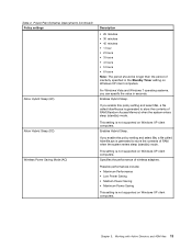
... contents of wireless adapters. Enables Hybrid Sleep. Chapter 3. This setting is not supported on Windows XP client computers. Specifies the performance of RAM (Random Access Memory) when the system enters sleep (standby) mode. For Windows Vista and Windows 7 operating systems, you enable this policy setting and select On, a file called hiberfile...
... contents of wireless adapters. Enables Hybrid Sleep. Chapter 3. This setting is not supported on Windows XP client computers. Specifies the performance of RAM (Random Access Memory) when the system enters sleep (standby) mode. For Windows Vista and Windows 7 operating systems, you enable this policy setting and select On, a file called hiberfile...
Hardware Maintenance Manual for ThinkCentre A70
Page 5
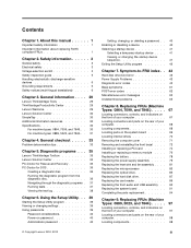
...70 Removing the computer cover 71 Removing and reinstalling the front bezel . . . . 72 Installing or replacing a PCI card 74 Installing or replacing a memory module . . . . 76 Replacing the battery 78 Replacing the power supply assembly . . . . . 79 Replacing the heat sink and fan assembly... connectors and parts on the rear of your computer 68 Locating components 68 Locating parts on password 40 Administrator password 40 © Copyright Lenovo 2010, 2012 Setting, changing, or deleting a password . . 40 Enabling or disabling a device 40 Selecting a startup device 41 Selecting...
...70 Removing the computer cover 71 Removing and reinstalling the front bezel . . . . 72 Installing or replacing a PCI card 74 Installing or replacing a memory module . . . . 76 Replacing the battery 78 Replacing the power supply assembly . . . . . 79 Replacing the heat sink and fan assembly... connectors and parts on the rear of your computer 68 Locating components 68 Locating parts on password 40 Administrator password 40 © Copyright Lenovo 2010, 2012 Setting, changing, or deleting a password . . 40 Enabling or disabling a device 40 Selecting a startup device 41 Selecting...
Hardware Maintenance Manual for ThinkCentre A70
Page 6
Notices 259 Television output notice 260 European conformance CE mark 260 Trademarks 260 Index 261 iv ThinkCentre Hardware Maintenance Manual Locating parts on the system board 99 Locating internal drives 100 Removing the computer cover 101 Removing... and reinstalling the front bezel . . . . 102 Accessing the system board components and drives 104 Installing or replacing a PCI card 105 Installing or replacing a memory module . . . . 107 Replacing the battery 109 Replacing the heat sink and fan assembly . . . . 110 Replacing the microprocessor 113 Replacing the power supply...
Notices 259 Television output notice 260 European conformance CE mark 260 Trademarks 260 Index 261 iv ThinkCentre Hardware Maintenance Manual Locating parts on the system board 99 Locating internal drives 100 Removing the computer cover 101 Removing... and reinstalling the front bezel . . . . 102 Accessing the system board components and drives 104 Installing or replacing a PCI card 105 Installing or replacing a memory module . . . . 107 Replacing the battery 109 Replacing the heat sink and fan assembly . . . . 110 Replacing the microprocessor 113 Replacing the power supply...
Hardware Maintenance Manual for ThinkCentre A70
Page 50
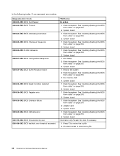
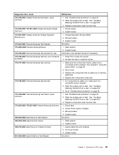
Flash the system. Run Setup 2. Flash the system. Run memory test 4. See "Updating (flashing) the BIOS from a disc" on page 255. 2. System board 1. Diagnostic Error Code 000-000-XXX BIOS Test Passed 000-002-XXX ... board 1. Flash the system. See "Updating (flashing) the BIOS from a disc" on page 255. 2. Flash the system. Press F3 to reset the log file 44 ThinkCentre Hardware Maintenance Manual Flash the system. See "Updating (flashing) the BIOS from a disc" on page 255. 2. System board 1. System board 1. Flash the system. Flash the...
Flash the system. Run Setup 2. Flash the system. Run memory test 4. See "Updating (flashing) the BIOS from a disc" on page 255. 2. System board 1. Diagnostic Error Code 000-000-XXX BIOS Test Passed 000-002-XXX ... board 1. Flash the system. See "Updating (flashing) the BIOS from a disc" on page 255. 2. Flash the system. Press F3 to reset the log file 44 ThinkCentre Hardware Maintenance Manual Flash the system. See "Updating (flashing) the BIOS from a disc" on page 255. 2. System board 1. System board 1. Flash the system. Flash the...
Hardware Maintenance Manual for ThinkCentre A70
Page 51
... a disc" on page 255 3. Replace component under test 1. Flash the system. System board No action System board System board System board 1. Flash the system. Run memory test 4. System board 1. See "Updating (flashing) the BIOS from a disc" on page 255 2. Go to "Undetermined problems" on page 39 2. Flash the system. Replace the...
... a disc" on page 255 3. Replace component under test 1. Flash the system. System board No action System board System board System board 1. Flash the system. Run memory test 4. System board 1. See "Updating (flashing) the BIOS from a disc" on page 255 2. Go to "Undetermined problems" on page 39 2. Flash the system. Replace the...
Hardware Maintenance Manual for ThinkCentre A70
Page 57
... is connected and/or enabled 2. Replace component under test 1. Flash the system and re-test. Go to -FRU index 51 System board System board 1. Run memory test 4. Flash the system.
... is connected and/or enabled 2. Replace component under test 1. Flash the system and re-test. Go to -FRU index 51 System board System board 1. Run memory test 4. Flash the system.
Hardware Maintenance Manual for ThinkCentre A70
Page 65
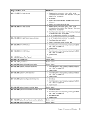
... error 185-000-XXX Asset Security Test Passed 185-XXX-XXX Asset Security failure 185-278-XXX Asset Security Chassis Intrusion 201-000-XXX System Memory Test Passed FRU/Action 1. Re-start the test, if necessary 1. Power supply 2. Flash the system and re-test. Flash system 2.
... error 185-000-XXX Asset Security Test Passed 185-XXX-XXX Asset Security failure 185-278-XXX Asset Security Chassis Intrusion 201-000-XXX System Memory Test Passed FRU/Action 1. Re-start the test, if necessary 1. Power supply 2. Flash the system and re-test. Flash system 2.
Hardware Maintenance Manual for ThinkCentre A70
Page 66
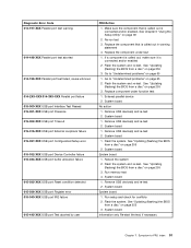
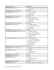
...No action 1. Check power supply voltages 3. Reseat the hard disk drive cable 4. Diskette drive 4. Check power supply voltages 3. Replace the memory module called out by the test 2. CD-ROM Drive Cable 2. Reseat the hard disk drive cable 4. Hard Disk Drive Cable 2. SCSI... Hard Disk Drive Cable 2. System board No action 1. System board No action Remove the Joystick and re-test the system 60 ThinkCentre Hardware Maintenance Manual Diskette Drive Cable 2. Mouse 2. System board 3. Check and test Keyboard 3. Check power supply voltages 3. Diagnostic Error...
...No action 1. Check power supply voltages 3. Reseat the hard disk drive cable 4. Diskette drive 4. Check power supply voltages 3. Replace the memory module called out by the test 2. CD-ROM Drive Cable 2. Reseat the hard disk drive cable 4. Hard Disk Drive Cable 2. SCSI... Hard Disk Drive Cable 2. System board No action 1. System board No action Remove the Joystick and re-test the system 60 ThinkCentre Hardware Maintenance Manual Diskette Drive Cable 2. Mouse 2. System board 3. Check and test Keyboard 3. Check power supply voltages 3. Diagnostic Error...
Hardware Maintenance Manual for ThinkCentre A70
Page 67
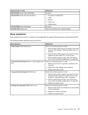
...setting error 1 long and 2 short beeps Monitor or video adapter card error 1 long and 9 short beeps BIOS ROM error Continuous long beeps DRAM memory error FRU/Action Perform the following actions in order. 1. Start the Setup Utility program and press F10 to Save and exit. 3. See "Recovering ... the connector(s). 2. Start the Setup Utility program and press F9 to load defaults and then press F10 to -FRU index 61 Make sure the memory module(s) are tones or a series of tones separated by pauses (intervals without sound) during POST. Symptom-to Save and exit. See "Recovering ...
...setting error 1 long and 2 short beeps Monitor or video adapter card error 1 long and 9 short beeps BIOS ROM error Continuous long beeps DRAM memory error FRU/Action Perform the following actions in order. 1. Start the Setup Utility program and press F10 to Save and exit. 3. See "Recovering ... the connector(s). 2. Start the Setup Utility program and press F9 to load defaults and then press F10 to -FRU index 61 Make sure the memory module(s) are tones or a series of tones separated by pauses (intervals without sound) during POST. Symptom-to Save and exit. See "Recovering ...
Hardware Maintenance Manual for ThinkCentre A70
Page 68
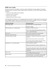
... KEYBOARD. A single problem can cause several error messages to NONE. Replace the battery. Checksum of the memory error. 62 ThinkCentre Hardware Maintenance Manual The computer loads the default configuration settings. Pressing Esc skips the full memory test Cannot find or initialize the hard disk drive controller or the drive. Cannot initialize the keyboard...
... KEYBOARD. A single problem can cause several error messages to NONE. Replace the battery. Checksum of the memory error. 62 ThinkCentre Hardware Maintenance Manual The computer loads the default configuration settings. Pressing Esc skips the full memory test Cannot find or initialize the hard disk drive controller or the drive. Cannot initialize the keyboard...

Hardware Maintenance Manual for ThinkCentre A70
Page 69
...) 1. Network adapter (advise network administrator of new MAC address) Computer will not perform a Wake on LAN feature is enabled for RPL 3. Memory Module 3. System Board 3. Riser card, if installed Computer will not power-off. Ensure that network is active. Ensure no interrupt or I/O ...not light when drive is in Setup/Configuration (see "Starting the Setup Utility program" on LAN 3. Diskette Drive 2. Run the Memory tests 2. Ensure that the operating system settings are set to the computer. Power Supply 2. Make sure you have bootable media. Flashing...
...) 1. Network adapter (advise network administrator of new MAC address) Computer will not perform a Wake on LAN feature is enabled for RPL 3. Memory Module 3. System Board 3. Riser card, if installed Computer will not power-off. Ensure that network is active. Ensure no interrupt or I/O ...not light when drive is in Setup/Configuration (see "Starting the Setup Utility program" on LAN 3. Diskette Drive 2. Run the Memory tests 2. Ensure that the operating system settings are set to the computer. Power Supply 2. Make sure you have bootable media. Flashing...
Hardware Maintenance Manual for ThinkCentre A70
Page 71
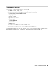
... and adapter cards have been removed, and the problem continues, replace the system board. a. Extended video memory e. External Cache RAM g. Symptom-to re-test the system. 4. Turn on page 123. Hard disk drive h. External Cache f. Memory modules d. Repeat steps 1 through 3 until you encounter undetermined problems, do the following components (if installed) one...
... and adapter cards have been removed, and the problem continues, replace the system board. a. Extended video memory e. External Cache RAM g. Symptom-to re-test the system. 4. Turn on page 123. Hard disk drive h. External Cache f. Memory modules d. Repeat steps 1 through 3 until you encounter undetermined problems, do the following components (if installed) one...
Hardware Maintenance Manual for ThinkCentre A70
Page 75
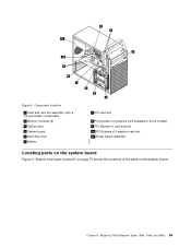
Replacing FRUs (Machine Types: 0864, 7099, and 7846.) 69 Component locations 1 Heat sink and fan assembly (with a microprocessor underneath) 2 Memory modules (2) 3 Optical drive 4 System board 5 Hard disk drive 6 Battery 7 PCI card slot 8 PCI Express x16 graphics card (available in some models) 9 PCI Express x1 card slots (2) 10 PCI Express x16 graphics card slot 11 Power supply assembly Locating parts on the system board Figure 4 "System board part locations" on page 70 shows the locations of the parts on the system board. Figure 3. Chapter 8.
Replacing FRUs (Machine Types: 0864, 7099, and 7846.) 69 Component locations 1 Heat sink and fan assembly (with a microprocessor underneath) 2 Memory modules (2) 3 Optical drive 4 System board 5 Hard disk drive 6 Battery 7 PCI card slot 8 PCI Express x16 graphics card (available in some models) 9 PCI Express x1 card slots (2) 10 PCI Express x16 graphics card slot 11 Power supply assembly Locating parts on the system board Figure 4 "System board part locations" on page 70 shows the locations of the parts on the system board. Figure 3. Chapter 8.
Hardware Maintenance Manual for ThinkCentre A70
Page 76
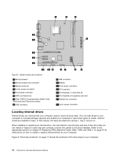
... bays in each bay and correctly connect the cables to read and store data. System board part locations 1 Microprocessor 2 Microprocessor fan connector 3 Memory slots (2) 4 24-pin power connector 5 Front panel connector 6 SATA connectors (3) 7 Clear CMOS (Complementary Metal Oxide Semiconductor) /Recovery jumper...computer. When installing or replacing an internal drive, it is important to increase storage capacity and enable your computer. 70 ThinkCentre Hardware Maintenance Manual Figure 5 "Drive bay locations" on . Internal drives are devices that you can add drives to ...
... bays in each bay and correctly connect the cables to read and store data. System board part locations 1 Microprocessor 2 Microprocessor fan connector 3 Memory slots (2) 4 24-pin power connector 5 Front panel connector 6 SATA connectors (3) 7 Clear CMOS (Complementary Metal Oxide Semiconductor) /Recovery jumper...computer. When installing or replacing an internal drive, it is important to increase storage capacity and enable your computer. 70 ThinkCentre Hardware Maintenance Manual Figure 5 "Drive bay locations" on . Internal drives are devices that you can add drives to ...
Hardware Maintenance Manual for ThinkCentre A70
Page 82
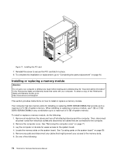
...lenovo.com/support This section provides instructions on its side for installing or replacing DDR3 SDRAM DIMMs that might prevent your computer. Then, disconnect all power cords from the drives and turn off all cables that came with your access to the memory slots. 6. Locate the memory.... 8. Lay the computer on how to a maximum of 4 GB of the following : 1. To install or replace a memory module, do the following : 76 ThinkCentre Hardware Maintenance Manual Remove all media from electrical outlets and disconnect all attached devices and the computer. To obtain a copy of ...
...lenovo.com/support This section provides instructions on its side for installing or replacing DDR3 SDRAM DIMMs that might prevent your computer. Then, disconnect all power cords from the drives and turn off all cables that came with your access to the memory slots. 6. Locate the memory.... 8. Lay the computer on how to a maximum of 4 GB of the following : 1. To install or replace a memory module, do the following : 76 ThinkCentre Hardware Maintenance Manual Remove all media from electrical outlets and disconnect all attached devices and the computer. To obtain a copy of ...


