
Hardware Maintenance Manual
Page 93
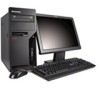
... the ThinkCentre Safety and Warranty Guide, go to: http://www.lenovo.com/support This section provides instructions on the left-side cover and slide the cover to the rear to remove the computer cover. To remove the computer cover: 1. If there are connected to the computer. 4. Tower Computers ...on how to remove. Unplug all cables attached to let the computer cool before reading and understanding the "Important safety information" in the ThinkCentre Safety and Warranty Guide that secure the computer cover, remove them. 5. Disconnect all power cords from the drives, and turn off ...
... the ThinkCentre Safety and Warranty Guide, go to: http://www.lenovo.com/support This section provides instructions on the left-side cover and slide the cover to the rear to remove the computer cover. To remove the computer cover: 1. If there are connected to the computer. 4. Tower Computers ...on how to remove. Unplug all cables attached to let the computer cool before reading and understanding the "Important safety information" in the ThinkCentre Safety and Warranty Guide that secure the computer cover, remove them. 5. Disconnect all power cords from the drives, and turn off ...
Hardware Maintenance Manual
Page 95
... the computer cover" on how to remove and reinstall the front bezel. Replacing FRUs - Remove the computer cover. To remove and reinstall the front bezel: 1. Tower Computers 89 Chapter 8.
... the computer cover" on how to remove and reinstall the front bezel. Replacing FRUs - Remove the computer cover. To remove and reinstall the front bezel: 1. Tower Computers 89 Chapter 8.

Hardware Maintenance Manual
Page 97
... the voltage available at the rear of the chassis. 4. Lift the power supply out of the drives. 10. Note: Use only the screws provided by Lenovo. 8. Go to 115 V. v If the voltage supply range in your local country or region is 100-127 V AC, set the switch to the ...connector to secure the power supply. Replacing FRUs - v If the voltage supply range in the chassis. 7. Reconnect the power supply connectors to 230 V. 6. Chapter 8. Tower Computers 91 Install the new power supply into the chassis so that the screw holes in the power supply align with those in your local...
... the voltage available at the rear of the chassis. 4. Lift the power supply out of the drives. 10. Note: Use only the screws provided by Lenovo. 8. Go to 115 V. v If the voltage supply range in your local country or region is 100-127 V AC, set the switch to the ...connector to secure the power supply. Replacing FRUs - v If the voltage supply range in the chassis. 7. Reconnect the power supply connectors to 230 V. 6. Chapter 8. Tower Computers 91 Install the new power supply into the chassis so that the screw holes in the power supply align with those in your local...

Hardware Maintenance Manual
Page 99
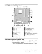
... the system board and disconnect all cables. See "Locating parts on the system board" on the new system board. 10. Rotate handle 1 to the chassis. 8. Tower Computers 93 6. Chapter 8. Lift the system board out of all cable connections on the new system board. Lift the heat sink and fan assembly off...
... the system board and disconnect all cables. See "Locating parts on the system board" on the new system board. 10. Rotate handle 1 to the chassis. 8. Tower Computers 93 6. Chapter 8. Lift the system board out of all cable connections on the new system board. Lift the heat sink and fan assembly off...

Hardware Maintenance Manual
Page 101
... on the microprocessor socket and then position the clamp on page 89. 25. See "Locating parts on the system board" on the plastic retention bracket. Tower Computers 95 Connect the heat sink and fan assembly cable to secure the microprocessor in the socket. 19. See "Locating parts on the system board...
... on the microprocessor socket and then position the clamp on page 89. 25. See "Locating parts on the system board" on the plastic retention bracket. Tower Computers 95 Connect the heat sink and fan assembly cable to secure the microprocessor in the socket. 19. See "Locating parts on the system board...

Hardware Maintenance Manual
Page 103
... socket might look different than the one corner of the microprocessor in the socket. The socket pins must touch the microprocessor, touch only the sides. 7. Tower Computers 97 6. b. Do not drop anything onto the microprocessor socket while it is important when reinstalling the microprocessor on the new system board. To release...
... socket might look different than the one corner of the microprocessor in the socket. The socket pins must touch the microprocessor, touch only the sides. 7. Tower Computers 97 6. b. Do not drop anything onto the microprocessor socket while it is important when reinstalling the microprocessor on the new system board. To release...

Hardware Maintenance Manual
Page 105
...Remove the memory module being replaced by opening the retaining clips as shown. To obtain a copy of the ThinkCentre Safety and Warranty Guide, go to: http://www.lenovo.com/support This section provides instructions on how to lay the computer on its side. 2. Remove the ...it helps to replace a memory module. Tower Computers 99 Chapter 8. To replace a memory module: 1. Replacing a memory module Attention Do not open your computer or attempt any repair before reading and understanding the "Important safety information" in the ThinkCentre Safety and Warranty Guide that came with...
...Remove the memory module being replaced by opening the retaining clips as shown. To obtain a copy of the ThinkCentre Safety and Warranty Guide, go to: http://www.lenovo.com/support This section provides instructions on how to lay the computer on its side. 2. Remove the ...it helps to replace a memory module. Tower Computers 99 Chapter 8. To replace a memory module: 1. Replacing a memory module Attention Do not open your computer or attempt any repair before reading and understanding the "Important safety information" in the ThinkCentre Safety and Warranty Guide that came with...

Hardware Maintenance Manual
Page 107
2. Tower Computers 101 Chapter 8. At the rear of the computer, press the release button 1 to open the PCI adapter card latch 2 and remove the PCI adapter card by pulling it straight out of the slot. Replacing FRUs -
2. Tower Computers 101 Chapter 8. At the rear of the computer, press the release button 1 to open the PCI adapter card latch 2 and remove the PCI adapter card by pulling it straight out of the slot. Replacing FRUs -

Hardware Maintenance Manual
Page 109
Pull on the blue handle 3 to free it outward. 5. Tower Computers 103 Remove the hard disk drive cage from the chassis by flexing the sides of the bracket enough to remove hard disk drive from the hard disk drive. 3. Replacing FRUs - Chapter 8. Press the release tab 1 down, slide the hard drive cage 2 back, and pivot the hard disk drive outward as shown. 4. Disconnect the signal and power cables from the drive cage. 6. 2. Remove the failing hard disk drive from the blue plastic bracket from by simply sliding it from the hard disk drive.
Pull on the blue handle 3 to free it outward. 5. Tower Computers 103 Remove the hard disk drive cage from the chassis by flexing the sides of the bracket enough to remove hard disk drive from the hard disk drive. 3. Replacing FRUs - Chapter 8. Press the release tab 1 down, slide the hard drive cage 2 back, and pivot the hard disk drive outward as shown. 4. Disconnect the signal and power cables from the drive cage. 6. 2. Remove the failing hard disk drive from the blue plastic bracket from by simply sliding it from the hard disk drive.

Hardware Maintenance Manual
Page 111
...any repair before reading and understanding the "Important safety information" in the ThinkCentre Safety and Warranty Guide that are two arrows, one on the upper drive cage and one on how to : http://www.lenovo.com/support This section provides instructions on the hard disk drive cage, ...into place. To replace the optical drive: 1. Disconnect the signal and power cables from the rear of the ThinkCentre Safety and Warranty Guide, go to replace the optical drive. Tower Computers 105 9. Replacing the optical drive Attention Do not open your computer. See "Removing the computer cover" ...
...any repair before reading and understanding the "Important safety information" in the ThinkCentre Safety and Warranty Guide that are two arrows, one on the upper drive cage and one on how to : http://www.lenovo.com/support This section provides instructions on the hard disk drive cage, ...into place. To replace the optical drive: 1. Disconnect the signal and power cables from the rear of the ThinkCentre Safety and Warranty Guide, go to replace the optical drive. Tower Computers 105 9. Replacing the optical drive Attention Do not open your computer. See "Removing the computer cover" ...

Hardware Maintenance Manual
Page 113
...replace the front fan assembly. See "Removing and reinstalling the front bezel" on page 89. Note the routing of the ThinkCentre Safety and Warranty Guide, go to: http://www.lenovo.com/support This section provides instructions on the new diskette drive. 6. Press the release button and slide the diskette drive ... the front fan assembly Attention Do not open your computer or attempt any repair before reading and understanding the "Important safety information" in the ThinkCentre Safety and Warranty Guide that came with your computer. See "Removing the computer cover" on page 114...
...replace the front fan assembly. See "Removing and reinstalling the front bezel" on page 89. Note the routing of the ThinkCentre Safety and Warranty Guide, go to: http://www.lenovo.com/support This section provides instructions on the new diskette drive. 6. Press the release button and slide the diskette drive ... the front fan assembly Attention Do not open your computer or attempt any repair before reading and understanding the "Important safety information" in the ThinkCentre Safety and Warranty Guide that came with your computer. See "Removing the computer cover" on page 114...

Hardware Maintenance Manual
Page 115
6. Route the fan cable to the system board and connect the cable to "Completing the FRU replacement" on page 89. 8. Go to the system board. Chapter 8. Tower Computers 109 See "Locating parts on the system board" on page 140. Replace the front bezel. 9. Replacing FRUs - Pull on the tips of the rubber mounts until the fan assembly is in place. 7.
6. Route the fan cable to the system board and connect the cable to "Completing the FRU replacement" on page 89. 8. Go to the system board. Chapter 8. Tower Computers 109 See "Locating parts on the system board" on page 140. Replace the front bezel. 9. Replacing FRUs - Pull on the tips of the rubber mounts until the fan assembly is in place. 7.

Hardware Maintenance Manual
Page 117
... page 89. To replace the front audio/USB assembly: 1. Remove the front bezel. Tower Computers 111 Pull on the tips of the rubber mounts until the fan assembly is in the ThinkCentre Safety and Warranty Guide that came with the holes on how to replace the front audio...USB assembly Attention Do not open your computer. Install the new rear fan assembly by aligning the rubber mounts of the ThinkCentre Safety and Warranty Guide, go to: http://www.lenovo.com/support This section provides instructions on the chassis and push the rubber mounts through the holes. 5. 4. Chapter 8....
... page 89. To replace the front audio/USB assembly: 1. Remove the front bezel. Tower Computers 111 Pull on the tips of the rubber mounts until the fan assembly is in the ThinkCentre Safety and Warranty Guide that came with the holes on how to replace the front audio...USB assembly Attention Do not open your computer. Install the new rear fan assembly by aligning the rubber mounts of the ThinkCentre Safety and Warranty Guide, go to: http://www.lenovo.com/support This section provides instructions on the chassis and push the rubber mounts through the holes. 5. 4. Chapter 8....
Hardware Maintenance Manual
Page 119
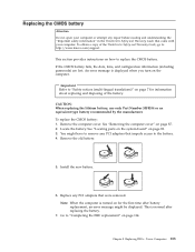
... an error message might have to remove any PCI adapters that impede access to : http://www.lenovo.com/support This section provides instructions on for information about replacing and disposing of the ThinkCentre Safety and Warranty Guide, go to the battery. 4. Important Refer to "Safety notices (multi-... passwords) are lost. Chapter 8. Go to replace the CMOS battery. Note: When the computer is displayed when you turn on page 87. 2. Tower Computers 113 Remove the old battery. 5. See "Locating parts on the system board" on page 114. To replace the CMOS battery: 1. Replacing the...
... an error message might have to remove any PCI adapters that impede access to : http://www.lenovo.com/support This section provides instructions on for information about replacing and disposing of the ThinkCentre Safety and Warranty Guide, go to the battery. 4. Important Refer to "Safety notices (multi-... passwords) are lost. Chapter 8. Go to replace the CMOS battery. Note: When the computer is displayed when you turn on page 87. 2. Tower Computers 113 Remove the old battery. 5. See "Locating parts on the system board" on page 114. To replace the CMOS battery: 1. Replacing the...

