Hardware Maintenance Manual
Page 5
... . 43 Problem determination tips 43 Chapter 5. Symptom-to-FRU Index . . . 53 © Lenovo 2005, 2008. Hard disk drive boot error 53 Power Supply Problems 53 Diagnostic error codes 54 Beep... system board 90 Replacing the heat sink and fan assembly . . . . 92 Replacing the microprocessor 94 Replacing a memory module 98 Installing or replacing an adapter card . . . . . 100 Replacing the primary hard disk drive .... Productivity Center program . . 39 Additional information resources 39 Specifications 40 Types 7258, 7260, 7268, 7270, 7280, 7296, 7298, 7304, 7307,7413, 7491, and 7508 40 Types ...
... . 43 Problem determination tips 43 Chapter 5. Symptom-to-FRU Index . . . 53 © Lenovo 2005, 2008. Hard disk drive boot error 53 Power Supply Problems 53 Diagnostic error codes 54 Beep... system board 90 Replacing the heat sink and fan assembly . . . . 92 Replacing the microprocessor 94 Replacing a memory module 98 Installing or replacing an adapter card . . . . . 100 Replacing the primary hard disk drive .... Productivity Center program . . 39 Additional information resources 39 Specifications 40 Types 7258, 7260, 7268, 7270, 7280, 7296, 7298, 7304, 7307,7413, 7491, and 7508 40 Types ...
Hardware Maintenance Manual
Page 60
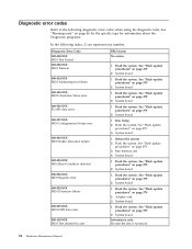
... 379 3. System board 1. Flash the system. See "Flash update procedures" on page 379 2. System board 1. Adapter card 3. See "Flash update procedures" on page 379 3. Run memory test 4. Flash the system. See "Flash update procedures" on page 379 2. Flash the system. System board 1. Flash the system. System board Information only Re-start...
... 379 3. System board 1. Flash the system. See "Flash update procedures" on page 379 2. System board 1. Adapter card 3. See "Flash update procedures" on page 379 3. Run memory test 4. Flash the system. See "Flash update procedures" on page 379 2. Flash the system. System board 1. Flash the system. System board Information only Re-start...
Hardware Maintenance Manual
Page 62
... card 2. See Chapter 6, "Using the Setup Utility," on page 379 3. Flash the system and retest. Go to "Undetermined problems" on system and re-test 2. Run memory test 4. Flash the system. See "Flash update procedures" on page 79 1. Power-off /on page 379 3. Re-run test 3. Flash the system. System board 1. System...
... card 2. See Chapter 6, "Using the Setup Utility," on page 379 3. Flash the system and retest. Go to "Undetermined problems" on system and re-test 2. Run memory test 4. Flash the system. See "Flash update procedures" on page 79 1. Power-off /on page 379 3. Re-run test 3. Flash the system. System board 1. System...
Hardware Maintenance Manual
Page 68
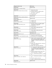
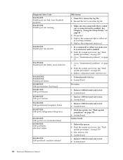
... 79 1. Replace the component that is called out is called out, make sure it is connected and/or enabled 2. System board 1. Reboot the system 2. Run memory test 4. System board 62 Hardware Maintenance Manual Diagnostic Error Code 014-196-XXX Parallel port test halt, error threshold exceeded 014-197-XXX Parallel port...
... 79 1. Replace the component that is called out is called out, make sure it is connected and/or enabled 2. System board 1. Reboot the system 2. Run memory test 4. System board 62 Hardware Maintenance Manual Diagnostic Error Code 014-196-XXX Parallel port test halt, error threshold exceeded 014-197-XXX Parallel port...

Hardware Maintenance Manual
Page 78
... Test Passed 185-XXX-XXX Asset Security failure 185-278-XXX Asset Security Chassis Intrusion 201-000-XXX System Memory Test Passed 201-XXX-XXX System Memory error 202-000-XXX System Cache Test Passed 202-XXX-XXX System Cache error 206-000-XXX Diskette Drive..."Flash update procedures" on page 379 3. See "Flash update procedures" on page 379 3. Replace component under test 1. System board No action 1. Replace the memory module called out is connected and/or enabled. System board 3. Diskette drive 4. Re-run test 3. System board No action 1. Cache, if removable 2. Go ...
... Test Passed 185-XXX-XXX Asset Security failure 185-278-XXX Asset Security Chassis Intrusion 201-000-XXX System Memory Test Passed 201-XXX-XXX System Memory error 202-000-XXX System Cache Test Passed 202-XXX-XXX System Cache error 206-000-XXX Diskette Drive..."Flash update procedures" on page 379 3. See "Flash update procedures" on page 379 3. Replace component under test 1. System board No action 1. Replace the memory module called out is connected and/or enabled. System board 3. Diskette drive 4. Re-run test 3. System board No action 1. Cache, if removable 2. Go ...
Hardware Maintenance Manual
Page 81
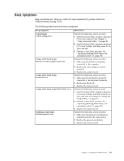
...Replace the system board. Replace the system board. See "Updating (flashing) BIOS from your operating system" on page 380. Make sure the memory module(s) are tones or a series of tones separated by pauses (intervals without sound) during POST. Start the Setup Utility program and press ... (flashing) BIOS from your operating system" on page 380. 3. Perform the following actions in order. 1. Replace the keyboard. 3. Replace the memory module(s). 3. Symptom-to Save and exit. Start the Setup Utility program and press F7 to load defaults and then press F10 to -FRU Index...
...Replace the system board. Replace the system board. See "Updating (flashing) BIOS from your operating system" on page 380. Make sure the memory module(s) are tones or a series of tones separated by pauses (intervals without sound) during POST. Start the Setup Utility program and press ... (flashing) BIOS from your operating system" on page 380. 3. Perform the following actions in order. 1. Replace the keyboard. 3. Replace the memory module(s). 3. Symptom-to Save and exit. Start the Setup Utility program and press F7 to load defaults and then press F10 to -FRU Index...
Hardware Maintenance Manual
Page 82
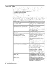
... the keyboard is properly connected to HALT ON ALL, BUT KEYBOARD. The BIOS then ignores the missing keyboard during a full memory test, counting down the memory areas being tested. POST error codes Each time you turn on the system. This series of the system and some basic ...working If the POST detects a problem, an error message appears on the screen. A single problem can cause several error messages to skip memory test HARD DISK INSTALL FAILURE The computer loads the default configuration settings. POST Error Message CMOS battery failed Description/Action The CMOS battery is...
... the keyboard is properly connected to HALT ON ALL, BUT KEYBOARD. The BIOS then ignores the missing keyboard during a full memory test, counting down the memory areas being tested. POST error codes Each time you turn on the system. This series of the system and some basic ...working If the POST detects a problem, an error message appears on the screen. A single problem can cause several error messages to skip memory test HARD DISK INSTALL FAILURE The computer loads the default configuration settings. POST Error Message CMOS battery failed Description/Action The CMOS battery is...
Hardware Maintenance Manual
Page 84
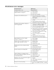
... 2. Ensure no interrupt or I/O address conflicts 6. System Board 1. Primary Hard Disk Drive 3. Run the Memory tests 2. System Board 1. See "Power Supply Problems" on page 53. See "Power Supply Problems" on LAN® 3. Incorrect memory size during POST ″Insert a Diskette″ icon appears with an otherwise blank display. Ensure that...-off. Ensure network administrator is enabled in startup sequence as first device or first device after diskette 2. Power Supply 2. System Board 3. System Board 2. Memory Module 3. System Board 2. Diskette Drive Cable 3.
... 2. Ensure no interrupt or I/O address conflicts 6. System Board 1. Primary Hard Disk Drive 3. Run the Memory tests 2. System Board 1. See "Power Supply Problems" on page 53. See "Power Supply Problems" on LAN® 3. Incorrect memory size during POST ″Insert a Diskette″ icon appears with an otherwise blank display. Ensure that...-off. Ensure network administrator is enabled in startup sequence as first device or first device after diskette 2. Power Supply 2. System Board 3. System Board 2. Memory Module 3. System Board 2. Diskette Drive Cable 3.
Hardware Maintenance Manual
Page 86
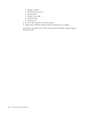
External Cache f. Diskette drive 3. External Cache RAM g. Power-on the computer to re-test the system. 4. Repeat steps 1 through 3 until you find the failing device or adapter. c. If all devices and adapters have been removed, and the problem continues, replace the system board. 80 Hardware Maintenance Manual Memory modules d. Extended video memory e. Hard disk drive h.
External Cache f. Diskette drive 3. External Cache RAM g. Power-on the computer to re-test the system. 4. Repeat steps 1 through 3 until you find the failing device or adapter. c. If all devices and adapters have been removed, and the problem continues, replace the system board. 80 Hardware Maintenance Manual Memory modules d. Extended video memory e. Hard disk drive h.

Hardware Maintenance Manual
Page 89
Computer components The following illustration will help you locate the major FRUs in the computer. 1 Heat sink, and fan assembly 2 Microprocessor 3 Memory 4 Optical drive 5 Diskette drive 6 Power switch / LED assembly 7 Internal speaker 8 Front audio / USB assembly 9 Hard disk drive 10 System board 11 Rear system fan 12 Power supply Chapter 8. Replacing FRUs - Tamdhu Computers 83
Computer components The following illustration will help you locate the major FRUs in the computer. 1 Heat sink, and fan assembly 2 Microprocessor 3 Memory 4 Optical drive 5 Diskette drive 6 Power switch / LED assembly 7 Internal speaker 8 Front audio / USB assembly 9 Hard disk drive 10 System board 11 Rear system fan 12 Power supply Chapter 8. Replacing FRUs - Tamdhu Computers 83

Hardware Maintenance Manual
Page 90
System board connectors This illustration is to help locate the various components and connectors on the system board. 1 Microprocessor 2 Microprocessor fan connector 3 Memory slots (2) 4 Thermal sensor connector 5 Diskette drive connector 6 24-pin power connector 7 Battery 8 Cover presence (Intrusion) switch connector 9 SATA connectors (4) 10 Clear CMOS (Complementary Metal Oxide ...
System board connectors This illustration is to help locate the various components and connectors on the system board. 1 Microprocessor 2 Microprocessor fan connector 3 Memory slots (2) 4 Thermal sensor connector 5 Diskette drive connector 6 24-pin power connector 7 Battery 8 Cover presence (Intrusion) switch connector 9 SATA connectors (4) 10 Clear CMOS (Complementary Metal Oxide ...

Hardware Maintenance Manual
Page 96
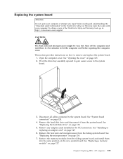
... side to remove and replace the system board. Remove any repair before beginning this procedure. Install the new retention module to : http://www.lenovo.com/support Note: When replacing the system board a new retention module for your computer or attempt any adapter cards installed in the new system... board. Remove the memory modules from the hard disk drive and remove the hard disk drive out of the ThinkCentre Safety and Warranty Guide, go to the new system board. 10. Install the new system ...
... side to remove and replace the system board. Remove any repair before beginning this procedure. Install the new retention module to : http://www.lenovo.com/support Note: When replacing the system board a new retention module for your computer or attempt any adapter cards installed in the new system... board. Remove the memory modules from the hard disk drive and remove the hard disk drive out of the ThinkCentre Safety and Warranty Guide, go to the new system board. 10. Install the new system ...
Hardware Maintenance Manual
Page 104
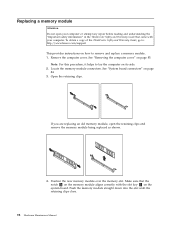
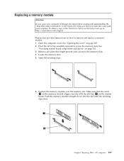
... the retaining clips and remove the memory module being replaced as shown. 4. Locate the memory module connectors. If you are replacing an old memory module, open your computer. To obtain a copy of the ThinkCentre Safety and Warranty Guide, go to: http://www.lenovo.com/support This provides instructions on... how to lay the computer on the system board. Note: For this procedure, it helps to remove and replace a memory module. 1. Make sure that came with...
... the retaining clips and remove the memory module being replaced as shown. 4. Locate the memory module connectors. If you are replacing an old memory module, open your computer. To obtain a copy of the ThinkCentre Safety and Warranty Guide, go to: http://www.lenovo.com/support This provides instructions on... how to lay the computer on the system board. Note: For this procedure, it helps to remove and replace a memory module. 1. Make sure that came with...

Hardware Maintenance Manual
Page 129
Replacing FRUs - 607 computers 123 Computer components The following illustration will help you locate the major FRUs in the computer. 1 Hard disk drive 2 Microprocessor, heat sink and fan assembly 3 Internal speaker (some models) 4 Optical drive 5 Memory slots (2) 6 Power supply assembly Chapter 9.
Replacing FRUs - 607 computers 123 Computer components The following illustration will help you locate the major FRUs in the computer. 1 Hard disk drive 2 Microprocessor, heat sink and fan assembly 3 Internal speaker (some models) 4 Optical drive 5 Memory slots (2) 6 Power supply assembly Chapter 9.

Hardware Maintenance Manual
Page 130
... slot 3 Internal speaker connector 4 Battery 5 Microprocessor fan connector 6 Thermal sensor connector 7 Cover presence (Intrusion) switch connector 8 Microprocessor 9 4-pin power connector 10 Front panel connector 11 Memory slots (2) 12 Front USB connectors (2) 13 Serial (COM 2) connector 14 Power fan connector 15 24-pin power connector 16 SATA connectors (2) 17 Clear CMOS (Complementary...
... slot 3 Internal speaker connector 4 Battery 5 Microprocessor fan connector 6 Thermal sensor connector 7 Cover presence (Intrusion) switch connector 8 Microprocessor 9 4-pin power connector 10 Front panel connector 11 Memory slots (2) 12 Front USB connectors (2) 13 Serial (COM 2) connector 14 Power fan connector 15 24-pin power connector 16 SATA connectors (2) 17 Clear CMOS (Complementary...
Hardware Maintenance Manual
Page 133
... any repair before reading and understanding the "Important safety information" in the ThinkCentre Safety and Warranty Guide that the notch 1 on the memory module aligns correctly with your computer. To obtain a copy of the ThinkCentre Safety and Warranty Guide, go to: http://www.lenovo.com/support This section provides instructions on how to the...
... any repair before reading and understanding the "Important safety information" in the ThinkCentre Safety and Warranty Guide that the notch 1 on the memory module aligns correctly with your computer. To obtain a copy of the ThinkCentre Safety and Warranty Guide, go to: http://www.lenovo.com/support This section provides instructions on how to the...
Hardware Maintenance Manual
Page 137
...how to remove and replace the system board. 1. Replacing FRUs - 607 computers 131 Remove the memory modules from the failing system board and install them into the same position on page 134. 7. ...Turn off the computer and wait three to five minutes to : http://www.lenovo.com/support CAUTION: The heat sink and microprocessor might be very hot. See "Replacing the ...microprocessor" on the new system board. To obtain a copy of the ThinkCentre Safety and Warranty Guide, go to let the computer cool before reading and understanding the "Important ...
...how to remove and replace the system board. 1. Replacing FRUs - 607 computers 131 Remove the memory modules from the failing system board and install them into the same position on page 134. 7. ...Turn off the computer and wait three to five minutes to : http://www.lenovo.com/support CAUTION: The heat sink and microprocessor might be very hot. See "Replacing the ...microprocessor" on the new system board. To obtain a copy of the ThinkCentre Safety and Warranty Guide, go to let the computer cool before reading and understanding the "Important ...

Hardware Maintenance Manual
Page 139
..."Installing or replacing an adapter card" on page 138. 12. See "Replacing the hard disk drive" on page 147. 11. See "Replacing a memory module" on page 150. Chapter 9. Reinstall the heat sink and microprocessor to the rear of the chassis until it is fully seated. 10. Reconnect ..."System board connectors" on page 134. 13. See "Replacing the microprocessor" on page 124. 15. Replacing FRUs - 607 computers 133 Reinstall the memory modules into the same position on the new system board. Reinstall the hard disk drive and connect the cables to "Completing the FRU replacement" on...
..."Installing or replacing an adapter card" on page 138. 12. See "Replacing the hard disk drive" on page 147. 11. See "Replacing a memory module" on page 150. Chapter 9. Reinstall the heat sink and microprocessor to the rear of the chassis until it is fully seated. 10. Reconnect ..."System board connectors" on page 134. 13. See "Replacing the microprocessor" on page 124. 15. Replacing FRUs - 607 computers 133 Reinstall the memory modules into the same position on the new system board. Reinstall the hard disk drive and connect the cables to "Completing the FRU replacement" on...
Hardware Maintenance Manual
Page 158
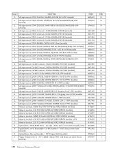
... (models) 2 Microprocessor, Q9300 Yorkfield 2.50GHZ 1333FSB 6M M-1 95W (models) 3 Memory module, 512MB PC2-5300 (667MHz) DDR2 SDRAM (models) 3 Memory module, 1GB PC2-5300 (667MHz) DDR2 SDRAM (models) 3 Memory module, 2GB PC2-5300 (667MHz) DDR2 SDRAM (models) 3 Memory module, 512MB PC2-6400 (800MHz) DDR2 SDRAM (models) 3 Memory module, 1GB PC2-6400 (667MHz) DDR2 SDRAM (models A1V...
... (models) 2 Microprocessor, Q9300 Yorkfield 2.50GHZ 1333FSB 6M M-1 95W (models) 3 Memory module, 512MB PC2-5300 (667MHz) DDR2 SDRAM (models) 3 Memory module, 1GB PC2-5300 (667MHz) DDR2 SDRAM (models) 3 Memory module, 2GB PC2-5300 (667MHz) DDR2 SDRAM (models) 3 Memory module, 512MB PC2-6400 (800MHz) DDR2 SDRAM (models) 3 Memory module, 1GB PC2-6400 (667MHz) DDR2 SDRAM (models A1V...

Hardware Maintenance Manual
Page 163
...- towerDVI+HDMI+DP (Tower) (models) ATI HD3470 GDDR3 256MB - LA high voltage (non-APU) (models) Speaker Power brick - 7258 Keyboard (Lenovo Preferred Pro PS/2 Full Size) Portuguese (models) Romanian (models) Russian/Cyrillic (models) Serbian/Cyrillic (models) Slovak (models) Spanish (models) Swedish/Finnish...Optical Wheel Mouse (400DPI, USB) (models A1V) PS/2 2 Button Ball Mouse (models) 7258 Adapters and miscellaneous FRUs Internal 20 in 1 USB Memory Card Reader(Tower) (models) IEEE 1394 Firewire Adapter SFF ( ROCKYS ) (models) Dash Marvell Ethernet card ATX Tower (models) Soft Modem V.90...
...- towerDVI+HDMI+DP (Tower) (models) ATI HD3470 GDDR3 256MB - LA high voltage (non-APU) (models) Speaker Power brick - 7258 Keyboard (Lenovo Preferred Pro PS/2 Full Size) Portuguese (models) Romanian (models) Russian/Cyrillic (models) Serbian/Cyrillic (models) Slovak (models) Spanish (models) Swedish/Finnish...Optical Wheel Mouse (400DPI, USB) (models A1V) PS/2 2 Button Ball Mouse (models) 7258 Adapters and miscellaneous FRUs Internal 20 in 1 USB Memory Card Reader(Tower) (models) IEEE 1394 Firewire Adapter SFF ( ROCKYS ) (models) Dash Marvell Ethernet card ATX Tower (models) Soft Modem V.90...


