
Lenovo H5 Series User Guide
Page 43
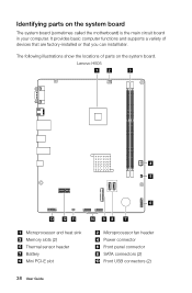
Identifying parts on the system board. Lenovo H505 12 3 4 5 6 13 12 11 10 9 8 7 Microprocessor and heat sink Memory slots (2) Thermal sensor header Battery Mini PCI-E slot Microprocessor fan header Power connector Front ... that you can install later. It provides basic computer functions and supports a variety of parts on the system board The system board (sometimes called the motherboard) is the main circuit board in your computer.
Identifying parts on the system board. Lenovo H505 12 3 4 5 6 13 12 11 10 9 8 7 Microprocessor and heat sink Memory slots (2) Thermal sensor header Battery Mini PCI-E slot Microprocessor fan header Power connector Front ... that you can install later. It provides basic computer functions and supports a variety of parts on the system board The system board (sometimes called the motherboard) is the main circuit board in your computer.
Lenovo H5 Series User Guide
Page 54
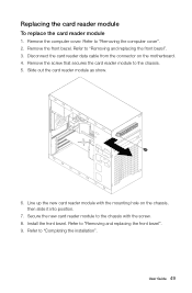
... module with the screw. 8. Refer to "Removing the computer cover". 2. Refer to "Completing the installation". Refer to the chassis with the mounting hole on the motherboard. 4. Install the front bezel. Secure the new card reader module to "Removing and replacing the front bezel". 9. User Guide 49 Remove the computer cover. Slide...
... module with the screw. 8. Refer to "Removing the computer cover". 2. Refer to "Completing the installation". Refer to the chassis with the mounting hole on the motherboard. 4. Install the front bezel. Secure the new card reader module to "Removing and replacing the front bezel". 9. User Guide 49 Remove the computer cover. Slide...
Lenovo H5 Series User Guide
Page 43
Lenovo H505 12 3 4 5 6 13 12 11 10 9 8 7 Microprocessor and heat sink Memory slots (2) Thermal sensor header Battery Mini PCI-E slot Microprocessor fan header Power connector Front ... that you can install later. It provides basic computer functions and supports a variety of parts on the system board The system board (sometimes called the motherboard) is the main circuit board in your computer.
Lenovo H505 12 3 4 5 6 13 12 11 10 9 8 7 Microprocessor and heat sink Memory slots (2) Thermal sensor header Battery Mini PCI-E slot Microprocessor fan header Power connector Front ... that you can install later. It provides basic computer functions and supports a variety of parts on the system board The system board (sometimes called the motherboard) is the main circuit board in your computer.

Lenovo H5 Series User Guide
Page 54
... show. 6. Refer to "Removing the computer cover". 2. Remove the screw that secures the card reader module to the chassis with the mounting hole on the motherboard. 4. Replacing the card reader module To replace the card reader module 1.
... show. 6. Refer to "Removing the computer cover". 2. Remove the screw that secures the card reader module to the chassis with the mounting hole on the motherboard. 4. Replacing the card reader module To replace the card reader module 1.

Lenovo H530 Hardware Maintenance Manual
Page 5
...problems 20 Chapter 7. Locating connectors, controls and components 21 Chapter 8. Contents Chapter 1. Using the Setup Utility. . . 13 Starting the Lenovo BIOS Setup Utility program . 13 Viewing and changing settings 13 Using passwords 13 Enabling or disabling a device 15 Selecting a startup device 16 ... supply 40 Replacing the Wi-Fi card 40 Replacing the front card reader module . . . . . 41 Replacing the motherboard 42 Chapter 9. About this manual 1 Important Safety Information 1 Chapter 2. FRU lists 45 Chapter 10. General information . . . . . 9 Specifications 9 Chapter...
...problems 20 Chapter 7. Locating connectors, controls and components 21 Chapter 8. Contents Chapter 1. Using the Setup Utility. . . 13 Starting the Lenovo BIOS Setup Utility program . 13 Viewing and changing settings 13 Using passwords 13 Enabling or disabling a device 15 Selecting a startup device 16 ... supply 40 Replacing the Wi-Fi card 40 Replacing the front card reader module . . . . . 41 Replacing the motherboard 42 Chapter 9. About this manual 1 Important Safety Information 1 Chapter 2. FRU lists 45 Chapter 10. General information . . . . . 9 Specifications 9 Chapter...
Lenovo H530 Hardware Maintenance Manual
Page 30
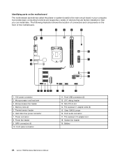
.... PCI express X 16 adapter slot 18. Battery 24 Lenovo H530Hardware Maintenance Manual Microprocessor and heat sink 3. Power connector 8. It provides basic computing functions and supports a variety of connectors and components on the motherboard The motherboard (sometimes called the planar or system board) is the main... circuit board in your computer. Mini PCI-E slot 14. Identifying parts on the front of the motherboard. 1 2 3 4 5 6 19 7 18 8 9 17 16 15 14 13 12 11 10 1. 12V power connector 2. The following ...
.... PCI express X 16 adapter slot 18. Battery 24 Lenovo H530Hardware Maintenance Manual Microprocessor and heat sink 3. Power connector 8. It provides basic computing functions and supports a variety of connectors and components on the motherboard The motherboard (sometimes called the planar or system board) is the main... circuit board in your computer. Mini PCI-E slot 14. Identifying parts on the front of the motherboard. 1 2 3 4 5 6 19 7 18 8 9 17 16 15 14 13 12 11 10 1. 12V power connector 2. The following ...
Lenovo H530 Hardware Maintenance Manual
Page 41
Step 8. Reattach the computer cover. Use a thermal grease syringe to the motherboard. To install the new heat-sink assembly: a. Line up the heat-sink to remove it with mounting holes on the grease syringe). Chapter 8. Replacing hardware ... heat-sink assembly to place five drops of grease on the top of grease should be 0.03ml (3 tick marks on the motherboard and secure it . Lift up the screws on the motherboard. Step 9. Each drop of the microprocessor. Reconnect the microprocessor fan power cable to lay the computer flat. c. Replacing an Intel...
Step 8. Reattach the computer cover. Use a thermal grease syringe to the motherboard. To install the new heat-sink assembly: a. Line up the heat-sink to remove it with mounting holes on the grease syringe). Chapter 8. Replacing hardware ... heat-sink assembly to place five drops of grease on the top of grease should be 0.03ml (3 tick marks on the motherboard and secure it . Lift up the screws on the motherboard. Step 9. Each drop of the microprocessor. Reconnect the microprocessor fan power cable to lay the computer flat. c. Replacing an Intel...
Lenovo H530 Hardware Maintenance Manual
Page 43
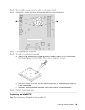
... the gold contacts on the grease syringe). Holding the sides of the microprocessor with your fingers, remove the protective cover 1 that the notches on the motherboard. Step 10. To secure the microprocessor in the microprocessor socket. Step 11. Reattach the heat-sink assembly and the computer cover. This includes power cords...
... the gold contacts on the grease syringe). Holding the sides of the microprocessor with your fingers, remove the protective cover 1 that the notches on the motherboard. Step 10. To secure the microprocessor in the microprocessor socket. Step 11. Reattach the heat-sink assembly and the computer cover. This includes power cords...
Lenovo H530 Hardware Maintenance Manual
Page 44
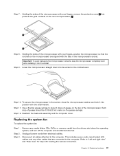
Pull the system fan assembly out of the chassis. 38 Lenovo H530Hardware Maintenance Manual Remove the computer cover. Refer to "Removing the computer cover". Step 6. Step 4. Disconnect the fan power cable from the connector on the motherboard. Step 5.
Pull the system fan assembly out of the chassis. 38 Lenovo H530Hardware Maintenance Manual Remove the computer cover. Refer to "Removing the computer cover". Step 6. Step 4. Disconnect the fan power cable from the connector on the motherboard. Step 5.

Lenovo H530 Hardware Maintenance Manual
Page 46
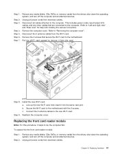
...output (I/O) cables, and any media (disks, CDs, DVDs, or memory cards) from electrical outlets. Disconnect the power cables from the connectors on motherboard. 1 Remove the 4 screws that are connected to the computer. b. Step 3. Replacing the Power supply Note: For this procedure, it helps to... 3 4 4 1 3 2 Step 8. To replace the Wi-Fi card: 40 Lenovo H530Hardware Maintenance Manual Remove the computer cover. Line up the holes on the new power supply with mounting holes on the motherboard. Connect the power cables to "Left and right view" and "Rear view" for help...
...output (I/O) cables, and any media (disks, CDs, DVDs, or memory cards) from electrical outlets. Disconnect the power cables from the connectors on motherboard. 1 Remove the 4 screws that are connected to the computer. b. Step 3. Replacing the Power supply Note: For this procedure, it helps to... 3 4 4 1 3 2 Step 8. To replace the Wi-Fi card: 40 Lenovo H530Hardware Maintenance Manual Remove the computer cover. Line up the holes on the new power supply with mounting holes on the motherboard. Connect the power cables to "Left and right view" and "Rear view" for help...
Lenovo H530 Hardware Maintenance Manual
Page 47
...cords from the Wi-Fi card. Chapter 8. Refer to the computer. Disconnect the 2 antenna cables from electrical outlets. Connect the 2 antenna cables to the motherboard with locating the various connectors. To replace the the front card reader module: Step 1. Unplug all cables attached to "Removing the computer cover". b. Secure the... Wi-Fi card to the new Wi-Fi card. Remove any other cables that secure the Wi-Fi card to the motherboard. Step 7. Remove the 2 screws that are connected to lay the computer flat. Step 2. Install the new Wi-Fi card: a.
...cords from the Wi-Fi card. Chapter 8. Refer to the computer. Disconnect the 2 antenna cables from electrical outlets. Connect the 2 antenna cables to the motherboard with locating the various connectors. To replace the the front card reader module: Step 1. Unplug all cables attached to "Removing the computer cover". b. Secure the... Wi-Fi card to the new Wi-Fi card. Remove any other cables that secure the Wi-Fi card to the motherboard. Step 7. Remove the 2 screws that are connected to lay the computer flat. Step 2. Install the new Wi-Fi card: a.
Lenovo H530 Hardware Maintenance Manual
Page 48
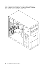
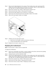
...operating system, and turn off the computer and all cables attached to the computer. b. Connect the data cables to "Removing the front bezel". Replacing the motherboard Note: For this procedure, it with locating the various connectors. Step 2. This includes power cords, input/output (I /O) cables, and any other cables ...and right view" and "Rear view" for help with locating the various connectors. Remove the computer cover. Refer to "Replacing a memory module". 42 Lenovo H530Hardware Maintenance Manual Remove the front bezel. Refer to "Removing the computer cover".
...operating system, and turn off the computer and all cables attached to the computer. b. Connect the data cables to "Removing the front bezel". Replacing the motherboard Note: For this procedure, it with locating the various connectors. Step 2. This includes power cords, input/output (I /O) cables, and any other cables ...and right view" and "Rear view" for help with locating the various connectors. Remove the computer cover. Refer to "Replacing a memory module". 42 Lenovo H530Hardware Maintenance Manual Remove the front bezel. Refer to "Removing the computer cover".
Lenovo H530 Hardware Maintenance Manual
Page 49
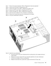
...Refer to "Replacing the Wi-Fi card". Step 14. Step 15. Install the new motherboard: a. Replacing hardware 43 Step 8. Refer to "Replacing the system fan". Remove the 6 screws that secure the motherboard to "Replacing the heat-sink assembly". b. c. Step 12. Step 10. Step ...13. Lift up the holes on the new motherboard with mounting holes on motherboard. Line up the motherboard to "Replacing the CPU". d. Remove the heat-sink assembly. Step 9. Remove the graphic card. Step 11. Refer...
...Refer to "Replacing the Wi-Fi card". Step 14. Step 15. Install the new motherboard: a. Replacing hardware 43 Step 8. Refer to "Replacing the system fan". Remove the 6 screws that secure the motherboard to "Replacing the heat-sink assembly". b. c. Step 12. Step 10. Step ...13. Lift up the holes on the new motherboard with mounting holes on motherboard. Line up the motherboard to "Replacing the CPU". d. Remove the heat-sink assembly. Step 9. Remove the graphic card. Step 11. Refer...
Lenovo H530 Hardware Maintenance Manual
Page 51
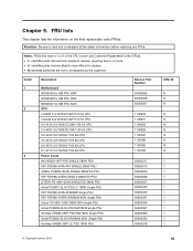
...: FRUs that are fairly simple to replace, requiring few or no tools. • 2- Item# 1 2 3 Description Motherboard 90002569 for MB FRU W8P 90002568 for MB FRU W8S 90002567 for MB FRU NOK CPU I G3220 3.0/1333/2C/3M/1150...1100785 1100783 36200511 36200510 36200509 36200508 36200507 36200430 36200429 36200427 36200426 36200367 36200366 36200323 36200218 CRU ID N N N N N N N N N N N 1 1 1 1 1 1 1 1 1 1 1 1 1 © Copyright Lenovo 2013 45 FRU lists This chapter lists the information on the field replaceable units (FRUs). identifies parts that are slightly more difficult to replace. •...
...: FRUs that are fairly simple to replace, requiring few or no tools. • 2- Item# 1 2 3 Description Motherboard 90002569 for MB FRU W8P 90002568 for MB FRU W8S 90002567 for MB FRU NOK CPU I G3220 3.0/1333/2C/3M/1150...1100785 1100783 36200511 36200510 36200509 36200508 36200507 36200430 36200429 36200427 36200426 36200367 36200366 36200323 36200218 CRU ID N N N N N N N N N N N 1 1 1 1 1 1 1 1 1 1 1 1 1 © Copyright Lenovo 2013 45 FRU lists This chapter lists the information on the field replaceable units (FRUs). identifies parts that are slightly more difficult to replace. •...


