User Guide
Page 7
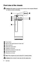
Front view of the chassis Attention: Be careful not to block any air vents on the computer. Blocked air vents can be placed in a vertical position. Power button Memory card reader (selected models only) USB connectors Optical drive eject button Headphone connector Optical Drive (selected models only) Hard disk drive indicator Microphone connector Note: This computer only can cause overheating. Attention: Do not insert 3-inch discs into the optical drive. 2 User Guide
Front view of the chassis Attention: Be careful not to block any air vents on the computer. Blocked air vents can be placed in a vertical position. Power button Memory card reader (selected models only) USB connectors Optical drive eject button Headphone connector Optical Drive (selected models only) Hard disk drive indicator Microphone connector Note: This computer only can cause overheating. Attention: Do not insert 3-inch discs into the optical drive. 2 User Guide
User Guide
Page 32
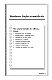
Hardware Replacement Guide This chapter contains the following topics: Identifying internal components Identifying parts on the system board Removing the computer cover Removing the front bezel Replacing a memory module Replacing a hard disk drive Replacing an optical drive Replacing the keyboard and mouse User Guide 27
Hardware Replacement Guide This chapter contains the following topics: Identifying internal components Identifying parts on the system board Removing the computer cover Removing the front bezel Replacing a memory module Replacing a hard disk drive Replacing an optical drive Replacing the keyboard and mouse User Guide 27
User Guide
Page 33
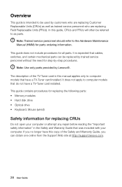
... guide is expected that cables, switches, and certain mechanical parts can obtain one online from the Support Web site at http://support.lenovo.com. 28 User Guide The description of the Safety and Warranty Guide, you no longer have this guide, CRUs and FRUs will...TV-Tuner card installed. This guide does not include procedures for parts ordering information. This guide contains procedures for replacing the following parts: • Memory modules • Hard disk drive • Optical drive • Keyboard, Mouse (wired) Safety information for step-by-step procedures. It is ...
... guide is expected that cables, switches, and certain mechanical parts can obtain one online from the Support Web site at http://support.lenovo.com. 28 User Guide The description of the Safety and Warranty Guide, you no longer have this guide, CRUs and FRUs will...TV-Tuner card installed. This guide does not include procedures for parts ordering information. This guide contains procedures for replacing the following parts: • Memory modules • Hard disk drive • Optical drive • Keyboard, Mouse (wired) Safety information for step-by-step procedures. It is ...

User Guide
Page 35
... your body. • When possible, remove the new part from the computer and you . • Always handle parts and other computer components carefully. Handle adapters, memory modules, system boards, and microprocessors by the edges. When this is not possible, place the anti-static package that the part came in your movement...
... your body. • When possible, remove the new part from the computer and you . • Always handle parts and other computer components carefully. Handle adapters, memory modules, system boards, and microprocessors by the edges. When this is not possible, place the anti-static package that the part came in your movement...

User Guide
Page 38
... on the system board The system board (sometimes called the planar or motherboard) is the main circuit board in your computer. Lenovo H505s 12 3 4 5 6 13 12 11 10 9 8 7 Microprocessor and heat sink Memory slots (2) Thermal sensor header Battery Mini PCI-E slot Clear CMOS jumper Front audio connector Microprocessor fan header Power connector Front...
... on the system board The system board (sometimes called the planar or motherboard) is the main circuit board in your computer. Lenovo H505s 12 3 4 5 6 13 12 11 10 9 8 7 Microprocessor and heat sink Memory slots (2) Thermal sensor header Battery Mini PCI-E slot Clear CMOS jumper Front audio connector Microprocessor fan header Power connector Front...
User Guide
Page 40
Note: Use only parts provided by Lenovo. Place the system on the rear of the computer". 4. This includes power cords, input/output (I/O) cables, and any repair before removing the cover. User Guide ..., and turn off the power to the computer. To remove the computer cover: 1. Refer to the Support Web site at http://support.lenovo.com. Remove any media (disks, CDs, or memory cards) from the drives, shut down before reading the "Important safety information" in the Hardware Maintenance Manual (HMM) for the computer...
Note: Use only parts provided by Lenovo. Place the system on the rear of the computer". 4. This includes power cords, input/output (I/O) cables, and any repair before removing the cover. User Guide ..., and turn off the power to the computer. To remove the computer cover: 1. Refer to the Support Web site at http://support.lenovo.com. Remove any media (disks, CDs, or memory cards) from the drives, shut down before reading the "Important safety information" in the Hardware Maintenance Manual (HMM) for the computer...
User Guide
Page 46
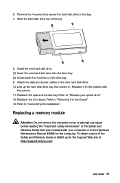
...chassis with your computer or in the Safety and Warranty Guide that secure the hard disk drive to the Support Web site at http://support.lenovo.com. Reattach the front bezel. User Guide 41 Install the new hard disk drive. (1) Insert the new hard disk drive into the drive... data and power cables to "Completing the installation". To obtain copies of the bay. 8. Refer to the new hard disk drive. 10. Replacing a memory module Attention: Do not remove the computer cover or attempt any repair before reading the "Important safety information" in the Hardware Maintenance Manual (HMM) for...
...chassis with your computer or in the Safety and Warranty Guide that secure the hard disk drive to the Support Web site at http://support.lenovo.com. Reattach the front bezel. User Guide 41 Install the new hard disk drive. (1) Insert the new hard disk drive into the drive... data and power cables to "Completing the installation". To obtain copies of the bay. 8. Refer to the new hard disk drive. 10. Replacing a memory module Attention: Do not remove the computer cover or attempt any repair before reading the "Important safety information" in the Hardware Maintenance Manual (HMM) for...

User Guide
Page 47
... is correctly aligned with the connector key on a flat, stable surface. 2. Locate the memory module connectors. Position the new memory module over the memory connector. Refer to "Locating components". 3. Remove the memory module being replaced by opening the retaining clips as shown. 4. Refer to lay the computer on the system board. Note: For this...
... is correctly aligned with the connector key on a flat, stable surface. 2. Locate the memory module connectors. Position the new memory module over the memory connector. Refer to "Locating components". 3. Remove the memory module being replaced by opening the retaining clips as shown. 4. Refer to lay the computer on the system board. Note: For this...
User Guide
Page 48
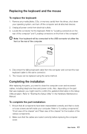
Remove any media (disks, CDs, or memory cards) from the drives, shut down your computer. Note: Your keyboard will be replaced using the same method. Make sure that the cables are left ...
Remove any media (disks, CDs, or memory cards) from the drives, shut down your computer. Note: Your keyboard will be replaced using the same method. Make sure that the cables are left ...


