
Hardware Maintenance Manual
Page 5
... connectors 67 Removing the cover 68 Locations 69 Locating parts on the system board 71 Removing and replacing the front bezel . . . . . 71 Replacing the power supply 72 Replacing the system board 73 Replacing the microprocessor 77 Replacing a memory module 79 Replacing a PCI adapter card 80 Replacing the hard disk drive 82 Replacing an optical drive 84 Replacing the diskette drive 85 Replacing the rear fan assembly 86 Replacing the front fan assembly 87 Replacing the front audio/USB assembly . . . . 89 Replacing the power switch/LED assembly . . . 89 Replacing the CMOS battery...
... connectors 67 Removing the cover 68 Locations 69 Locating parts on the system board 71 Removing and replacing the front bezel . . . . . 71 Replacing the power supply 72 Replacing the system board 73 Replacing the microprocessor 77 Replacing a memory module 79 Replacing a PCI adapter card 80 Replacing the hard disk drive 82 Replacing an optical drive 84 Replacing the diskette drive 85 Replacing the rear fan assembly 86 Replacing the front fan assembly 87 Replacing the front audio/USB assembly . . . . 89 Replacing the power switch/LED assembly . . . 89 Replacing the CMOS battery...
Hardware Maintenance Manual
Page 6
... battery 98 Replacing the power supply 99 Replacing the system board 100 Replacing the microprocessor 104 Replacing the hard disk drive 106 Replacing an optical drive 108 Replacing the diskette drive 109 Replacing the power switch/LED assembly . . . 109 Replacing the front panel card 110 Replacing the system fan assembly 111 Replacing a PCI adapter card 112 Completing the FRU replacement 113 Chapter 10. Additional Service Information 467 Security features 467 Hardware controlled Passwords 467 Operating system password 467 Vital product data 467 BIOS levels 467 Flash update...
... battery 98 Replacing the power supply 99 Replacing the system board 100 Replacing the microprocessor 104 Replacing the hard disk drive 106 Replacing an optical drive 108 Replacing the diskette drive 109 Replacing the power switch/LED assembly . . . 109 Replacing the front panel card 110 Replacing the system fan assembly 111 Replacing a PCI adapter card 112 Completing the FRU replacement 113 Chapter 10. Additional Service Information 467 Security features 467 Hardware controlled Passwords 467 Operating system password 467 Vital product data 467 BIOS levels 467 Flash update...
Hardware Maintenance Manual
Page 35
.... Specifications This section lists the physical specifications for your computer is preinstalled on most up-to other technical assistance. You can find the following information: • CRU removal and installation instructions • Publications • Troubleshooting information • Parts information • Downloads and drivers • Links to -date information for general information about the use, operation, and maintenance of information To access this publication. For machine types: 7057...
.... Specifications This section lists the physical specifications for your computer is preinstalled on most up-to other technical assistance. You can find the following information: • CRU removal and installation instructions • Publications • Troubleshooting information • Parts information • Downloads and drivers • Links to -date information for general information about the use, operation, and maintenance of information To access this publication. For machine types: 7057...
Hardware Maintenance Manual
Page 37
.... • Machine type and model • Processor or hard disk upgrades • Failure symptom - Power-on the computer. • Look for displayed error codes • Listen for beep codes • Look for readable instructions or a main menu on all display controls to "Diagnostic error codes" on page 467. Do diagnostics indicate a failure? - General Checkout Attention The drives in problem determination. For more information on how to help determine the cause of the system board. Run the Diagnostic programs...
.... • Machine type and model • Processor or hard disk upgrades • Failure symptom - Power-on the computer. • Look for displayed error codes • Listen for beep codes • Look for readable instructions or a main menu on all display controls to "Diagnostic error codes" on page 467. Do diagnostics indicate a failure? - General Checkout Attention The drives in problem determination. For more information on how to help determine the cause of the system board. Run the Diagnostic programs...

Hardware Maintenance Manual
Page 42
... of time to either the QUICK ERASE or FULL ERASE HARD DISK option and follow the instructions. The Full Erase Hard Drive provides a DOS utility that this is retrieved from CMOS and displayed using the Quick or Full Erase functions. Select either a fixed disk drive, removable media drive, serial or parallel port, processor, specific RIMM, or a device on the hard drive. • Destroys all partitions (both the master and backup). • Destroys the...
... of time to either the QUICK ERASE or FULL ERASE HARD DISK option and follow the instructions. The Full Erase Hard Drive provides a DOS utility that this is retrieved from CMOS and displayed using the Quick or Full Erase functions. Select either a fixed disk drive, removable media drive, serial or parallel port, processor, specific RIMM, or a device on the hard drive. • Destroys all partitions (both the master and backup). • Destroys the...
Hardware Maintenance Manual
Page 46
... Disable, all devices connected to the SATA controller (such as hard disk drives or the CD-ROM drive) are disabled and will not be displayed in the system configuration. From the Setup Utility program menu, select Devices ® SATA Drives Setup ® SATA 1 and press Enter. 3. Select the desired settings and press Enter. 5. If both the user and administrator passwords are set, you might want to save the settings, select Discard Changes or Discard Changes and Exit. 40 ThinkCentre Hardware Maintenance Manual Start the Setup Utility...
... Disable, all devices connected to the SATA controller (such as hard disk drives or the CD-ROM drive) are disabled and will not be displayed in the system configuration. From the Setup Utility program menu, select Devices ® SATA Drives Setup ® SATA 1 and press Enter. 3. Select the desired settings and press Enter. 5. If both the user and administrator passwords are set, you might want to save the settings, select Discard Changes or Discard Changes and Exit. 40 ThinkCentre Hardware Maintenance Manual Start the Setup Utility...
Hardware Maintenance Manual
Page 51
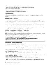
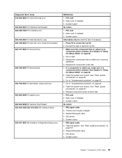
... System Configuration/Setup error 001-032-XXX System Device Controller failure 001-034-XXX System Device Buffer Allocation failure 001-035-XXX System Device Reset condition detected 001-036-XXX System Register error FRU/Action 1. Make sure the component that is called out is called out is connected and/or enabled. Flash the system. See "Flash update procedures" on page 467 2. Flash the system and retest. System board 1. Flash the...
... System Configuration/Setup error 001-032-XXX System Device Controller failure 001-034-XXX System Device Buffer Allocation failure 001-035-XXX System Device Reset condition detected 001-036-XXX System Register error FRU/Action 1. Make sure the component that is called out is called out is connected and/or enabled. Flash the system. See "Flash update procedures" on page 467 2. Flash the system and retest. System board 1. Flash the...
Hardware Maintenance Manual
Page 52
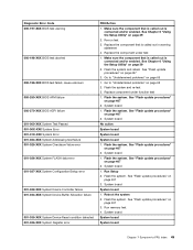
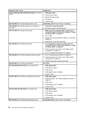
.../or enabled. System board 1. System board 1. System board Information only Re-start the test to "Undetermined problems" on page 65 2. Replace the component under function test System board System board System board 1. Replace component under test 1. System board 1. Press F3 to "Undetermined problems" on page 65 1. See Chapter 6 "Using the Setup Utility" on page 467 2. Go to review the log file 2. System board 1. Device on page 39 2. Diagnostic Error Code 001-038-XXX System Extension failure...
.../or enabled. System board 1. System board 1. System board Information only Re-start the test to "Undetermined problems" on page 65 2. Replace the component under function test System board System board System board 1. Replace component under test 1. System board 1. Press F3 to "Undetermined problems" on page 65 1. See Chapter 6 "Using the Setup Utility" on page 467 2. Go to review the log file 2. System board 1. Device on page 39 2. Diagnostic Error Code 001-038-XXX System Extension failure...
Hardware Maintenance Manual
Page 54
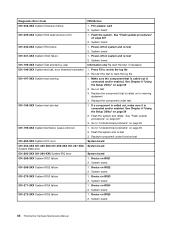
...-start the test to "Undetermined problems" on page 65 2. See Chapter 6 "Using the Setup Utility" on page 467 3. See "Flash update procedures" on page 39 2. Video card, if installed 2. Run Setup 2. Video drivers update 3. Monitor 3. Diagnostic Error Code 005-016-XXX Video Simple Pattern test failure 005-024-XXX Video Addressing test failure 005-025-XXX Video Checksum Value error 005-027-XXX Video Configuration/Setup error 005-031-XXX Video Device Cable failure 005-032-XXX Video Device Controller failure 005-036-XXX Video Register error 005-038-XXX System BIOS extension failure...
...-start the test to "Undetermined problems" on page 65 2. See Chapter 6 "Using the Setup Utility" on page 467 3. See "Flash update procedures" on page 39 2. Video card, if installed 2. Run Setup 2. Video drivers update 3. Monitor 3. Diagnostic Error Code 005-016-XXX Video Simple Pattern test failure 005-024-XXX Video Addressing test failure 005-025-XXX Video Checksum Value error 005-027-XXX Video Configuration/Setup error 005-031-XXX Video Device Cable failure 005-032-XXX Video Device Controller failure 005-036-XXX Video Register error 005-038-XXX System BIOS extension failure...
Hardware Maintenance Manual
Page 55
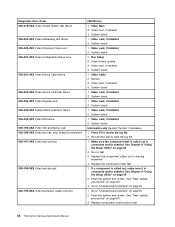
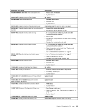
...-XXX Serial port Configuration/Setup error 011-03X-XXX 011-04X-XXX Serial port failure 011-195-XXX Serial port Test aborted by user FRU/Action 1. Video card, if installed 2. Diskette drive 3. Flash the system and re-test. See "Flash update procedures" on page 467 3. Flash the system and re-test 3. System board No action 1. System board System board System board 1. See "Flash update procedures" on page 467 3. System board Information only Re-start the test to reset the log file 1. Replace the...
...-XXX Serial port Configuration/Setup error 011-03X-XXX 011-04X-XXX Serial port failure 011-195-XXX Serial port Test aborted by user FRU/Action 1. Video card, if installed 2. Diskette drive 3. Flash the system and re-test. See "Flash update procedures" on page 467 3. Flash the system and re-test 3. System board No action 1. System board System board System board 1. See "Flash update procedures" on page 467 3. System board Information only Re-start the test to reset the log file 1. Replace the...
Hardware Maintenance Manual
Page 57
... USB port Presence 015-002-XXX USB port Timeout 015-015-XXX USB port External Loopback failure 015-027-XXX USB port Configuration/Setup error 015-032-XXX USB port Device Controller failure 015-034-XXX USB port buffer allocation failure 015-035-XXX USB port Reset condition detected 015-036-XXX USB port Register error 015-040-XXX USB port IRQ failure 015-195-XXX USB port Test aborted by user FRU/Action 1. Make sure the component that is connected and/or enabled 2. See Chapter 6 "Using the Setup Utility...
... USB port Presence 015-002-XXX USB port Timeout 015-015-XXX USB port External Loopback failure 015-027-XXX USB port Configuration/Setup error 015-032-XXX USB port Device Controller failure 015-034-XXX USB port buffer allocation failure 015-035-XXX USB port Reset condition detected 015-036-XXX USB port Register error 015-040-XXX USB port IRQ failure 015-195-XXX USB port Test aborted by user FRU/Action 1. Make sure the component that is connected and/or enabled 2. See Chapter 6 "Using the Setup Utility...
Hardware Maintenance Manual
Page 59
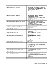
... power supply voltages 3. IDE signal cable 2. PCI card 2. Press F3 to "Undetermined problems" on page 467 3. Replace the component under function test 1. See "Flash update procedures" on page 39 2. Go to review the log file 2. See Chapter 6 "Using the Setup Utility" on page 467 3. IDE device 5. If a component is called out, make sure it is called out in warning statement 4. System board No action 1. Diagnostic Error Code 018-250-XXX PCI Card Services error...
... power supply voltages 3. IDE signal cable 2. PCI card 2. Press F3 to "Undetermined problems" on page 467 3. Replace the component under function test 1. See "Flash update procedures" on page 39 2. Go to review the log file 2. See Chapter 6 "Using the Setup Utility" on page 467 3. IDE device 5. If a component is called out, make sure it is called out in warning statement 4. System board No action 1. Diagnostic Error Code 018-250-XXX PCI Card Services error...
Hardware Maintenance Manual
Page 60
... test to review the log file 2. See Chapter 6 "Using the Setup Utility" on page 467 3. See "Flash update procedures" on page 467 3. Check power supply 3. SCSI signal cable 2. Replace component under test 1. Re-run test 3. System board Information only Re-start the test, if necessary 54 ThinkCentre Hardware Maintenance Manual Flash the system. Diagnostic Error Code 025-02X-XXX 025-03X-XXX 025-04X-XXX IDE Interface failure 025-195-XXX IDE interface Test aborted by user...
... test to review the log file 2. See Chapter 6 "Using the Setup Utility" on page 467 3. See "Flash update procedures" on page 467 3. Check power supply 3. SCSI signal cable 2. Replace component under test 1. Re-run test 3. System board Information only Re-start the test, if necessary 54 ThinkCentre Hardware Maintenance Manual Flash the system. Diagnostic Error Code 025-02X-XXX 025-03X-XXX 025-04X-XXX IDE Interface failure 025-195-XXX IDE interface Test aborted by user...
Hardware Maintenance Manual
Page 68
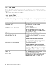
... the computer and that CMOS has become corrupt due to skip memory test HARD DISK INSTALL FAILURE Keyboard error or no keyboard present Memory Test: Memory test fail Description/Action The CMOS battery is no keys are installed, make sure the hard disk drive selection in Setup is set the error halt condition in Setup to NONE. Make sure the keyboard is working If the POST detects a problem, an error message appears on the screen. POST does the following operations. • Checks some options.
... the computer and that CMOS has become corrupt due to skip memory test HARD DISK INSTALL FAILURE Keyboard error or no keyboard present Memory Test: Memory test fail Description/Action The CMOS battery is no keys are installed, make sure the hard disk drive selection in Setup is set the error halt condition in Setup to NONE. Make sure the keyboard is working If the POST detects a problem, an error message appears on the screen. POST does the following operations. • Checks some options.

Hardware Maintenance Manual
Page 69
...disk or disk error Replace and press any key when ready Description/Action Pressing the TAB key permits the user to network adapter 2. Check power supply and signal cable connections to toggle between the default POST display screen and a custom POST display screen. Power Supply 2. Diskette Drive Cable Flashing cursor with an otherwise blank display. 1. Run the Memory tests 2. Make sure the boot drive is using correct MAC address 5. Power Switch 2. Ensure that network adapter is in startup sequence as first device or first device after diskette 2. See "Hard disk drive boot error...
...disk or disk error Replace and press any key when ready Description/Action Pressing the TAB key permits the user to network adapter 2. Check power supply and signal cable connections to toggle between the default POST display screen and a custom POST display screen. Power Supply 2. Diskette Drive Cable Flashing cursor with an otherwise blank display. 1. Run the Memory tests 2. Make sure the boot drive is using correct MAC address 5. Power Switch 2. Ensure that network adapter is in startup sequence as first device or first device after diskette 2. See "Hard disk drive boot error...

Hardware Maintenance Manual
Page 70
... Power switch/LED assembly but computer works correctly 2. Message/Symptom FRU/Action "Insert a Diskette" icon appears with a known-good diagnostics diskette in -use light not on, 1. See "Hard disk drive boot error" on the keyboard do not work 1. Power Supply RPL computer cannot access programs from server 1. System Board Power-on indicator or hard disk drive in the first 3.5-inch diskette drive. 1. First device - System Board 64 ThinkCentre Hardware Maintenance Manual System Board 2. Check the network adapter LED status Serial or parallel port device failure...
... Power switch/LED assembly but computer works correctly 2. Message/Symptom FRU/Action "Insert a Diskette" icon appears with a known-good diagnostics diskette in -use light not on, 1. See "Hard disk drive boot error" on the keyboard do not work 1. Power Supply RPL computer cannot access programs from server 1. System Board Power-on indicator or hard disk drive in the first 3.5-inch diskette drive. 1. First device - System Board 64 ThinkCentre Hardware Maintenance Manual System Board 2. Check the network adapter LED status Serial or parallel port device failure...
Hardware Maintenance Manual
Page 71
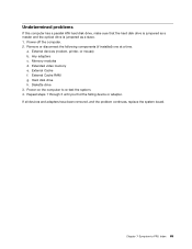
... you find the failing device or adapter. Power-off the computer. 2. Hard disk drive h. Diskette drive 3. Extended video memory e. If all devices and adapters have been removed, and the problem continues, replace the system board. Undetermined problems If this computer has a parallel ATA hard disk drive, make sure that the hard disk drive is jumpered as a master and the optical drive is jumpered as a slave. 1. a. External Cache RAM g. Chapter 7 Symptom-to re-test the system. 4. Memory modules d. Remove or disconnect the following...
... you find the failing device or adapter. Power-off the computer. 2. Hard disk drive h. Diskette drive 3. Extended video memory e. If all devices and adapters have been removed, and the problem continues, replace the system board. Undetermined problems If this computer has a parallel ATA hard disk drive, make sure that the hard disk drive is jumpered as a master and the optical drive is jumpered as a slave. 1. a. External Cache RAM g. Chapter 7 Symptom-to re-test the system. 4. Memory modules d. Remove or disconnect the following...
Hardware Maintenance Manual
Page 96
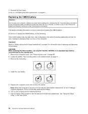
... not open your computer or attempt any passwords. See "Removing the cover" on the computer. Replace the computer cover, and connect the cables. To remove or replace the CMOS battery, do the following: If the CMOS battery fails, the date, time, and configuration information (including passwords) are lost. Note: When the computer is displayed when you turn on page 68. 2. 9. See "Using the Setup Utility" in the ThinkCentre Safety and Warranty Guide...
... not open your computer or attempt any passwords. See "Removing the cover" on the computer. Replace the computer cover, and connect the cables. To remove or replace the CMOS battery, do the following: If the CMOS battery fails, the date, time, and configuration information (including passwords) are lost. Note: When the computer is displayed when you turn on page 68. 2. 9. See "Using the Setup Utility" in the ThinkCentre Safety and Warranty Guide...
Hardware Maintenance Manual
Page 105
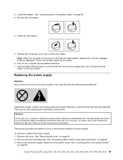
... error message might be displayed. Turn on how to set the date and time and any repair before reading and understanding the "Important safety information" in the User Guide Replacing the power supply Attention Never remove the cover on for the first time after replacing the battery. 6. See "Removing the cover" on page 95. See "Locating parts on the system board" on page 94. 2. Install the new battery. 5. See "Accessing system board components and drives...
... error message might be displayed. Turn on how to set the date and time and any repair before reading and understanding the "Important safety information" in the User Guide Replacing the power supply Attention Never remove the cover on for the first time after replacing the battery. 6. See "Removing the cover" on page 95. See "Locating parts on the system board" on page 94. 2. Install the new battery. 5. See "Accessing system board components and drives...

Hardware Maintenance Manual
Page 106
...-240 V ac, set the switch to remove the power supply. 6. Install the hard disk drive. Note: Observe the power supply cable routing underneath the hard disk drive. 5. Note: You do not have to remove the system board from the power supply. Using the blue handle, slide the drive bay assembly towards the rear of the chassis and place it snaps into position. Reinstall the front bezel. 16. See "Replacing the hard disk drive" on page 106...
...-240 V ac, set the switch to remove the power supply. 6. Install the hard disk drive. Note: Observe the power supply cable routing underneath the hard disk drive. 5. Note: You do not have to remove the system board from the power supply. Using the blue handle, slide the drive bay assembly towards the rear of the chassis and place it snaps into position. Reinstall the front bezel. 16. See "Replacing the hard disk drive" on page 106...


