Hardware Maintenance Manual
Page 5
... connectors 67 Removing the cover 68 Locations 69 Locating parts on the system board 71 Removing and replacing the front bezel . . . . . 71 Replacing the power supply 72 Replacing the system board 73 Replacing the microprocessor 77 Replacing a memory module 79 Replacing a PCI adapter card 80 Replacing the hard disk drive 82 Replacing an optical drive 84 Replacing the diskette drive 85 Replacing the rear fan assembly 86 Replacing the front fan assembly 87 Replacing the front audio/USB assembly . . . . 89 Replacing the power switch/LED assembly . . . 89 Replacing the CMOS battery...
... connectors 67 Removing the cover 68 Locations 69 Locating parts on the system board 71 Removing and replacing the front bezel . . . . . 71 Replacing the power supply 72 Replacing the system board 73 Replacing the microprocessor 77 Replacing a memory module 79 Replacing a PCI adapter card 80 Replacing the hard disk drive 82 Replacing an optical drive 84 Replacing the diskette drive 85 Replacing the rear fan assembly 86 Replacing the front fan assembly 87 Replacing the front audio/USB assembly . . . . 89 Replacing the power switch/LED assembly . . . 89 Replacing the CMOS battery...
Hardware Maintenance Manual
Page 6
...vi ThinkCentre Hardware Maintenance Manual 9426, 9486, 9624, 9707, 9787, 9804, 9945 93 Rear connectors 93 Removing the cover 94 Locations 94 Locating parts on the system board 95 Accessing system board components and drives . 96 Replacing a memory module 97 Replacing the CMOS battery 98 Replacing the power supply 99 Replacing the system board 100 Replacing the microprocessor 104 Replacing the hard disk drive 106 Replacing an optical drive 108 Replacing the diskette drive 109 Replacing the power switch/LED assembly . . . 109 Replacing the front panel card 110 Replacing the system...
...vi ThinkCentre Hardware Maintenance Manual 9426, 9486, 9624, 9707, 9787, 9804, 9945 93 Rear connectors 93 Removing the cover 94 Locations 94 Locating parts on the system board 95 Accessing system board components and drives . 96 Replacing a memory module 97 Replacing the CMOS battery 98 Replacing the power supply 99 Replacing the system board 100 Replacing the microprocessor 104 Replacing the hard disk drive 106 Replacing an optical drive 108 Replacing the diskette drive 109 Replacing the power switch/LED assembly . . . 109 Replacing the front panel card 110 Replacing the system...
Hardware Maintenance Manual
Page 35
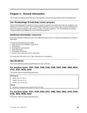
..., 9787, 9804, 9945 This section lists the physical specifications. The ThinkVantage Productivity Center program also contains information to other technical assistance. Chapter 3. You can find the following information: • CRU removal and installation instructions • Publications • Troubleshooting information • Parts information • Downloads and drivers • Links to help solve problems and get repair service or other useful sources of the computer. Dimensions Width...
..., 9787, 9804, 9945 This section lists the physical specifications. The ThinkVantage Productivity Center program also contains information to other technical assistance. Chapter 3. You can find the following information: • CRU removal and installation instructions • Publications • Troubleshooting information • Parts information • Downloads and drivers • Links to help solve problems and get repair service or other useful sources of the computer. Dimensions Width...
Hardware Maintenance Manual
Page 37
... rearranged or the drive startup sequence changed. Run the Diagnostic programs. See Chapter 5 "Diagnostics" on page 33. • If you cannot continue, replace the last device tested. Do diagnostics indicate a failure? - General error messages appear if a problem or conflict is installed on page 31. 7. Check all external devices. 2. If you are servicing might cause false errors and unnecessary replacement of BIOS is found by an application program, the operating system, or...
... rearranged or the drive startup sequence changed. Run the Diagnostic programs. See Chapter 5 "Diagnostics" on page 33. • If you cannot continue, replace the last device tested. Do diagnostics indicate a failure? - General error messages appear if a problem or conflict is installed on page 31. 7. Check all external devices. 2. If you are servicing might cause false errors and unnecessary replacement of BIOS is found by an application program, the operating system, or...

Hardware Maintenance Manual
Page 42
... for error code listings. To select the Quick Erase or Full Erase Hard Drive utility, use the following : • Destroys the Master Boot Record (MBR) on the hard drive. • Destroys all copies of the FAT Table on the PCI bus. • Date: Contains the date when the diagnostic test was run. Note: See "Diagnostic error codes" on the toolbar and press Enter. 2. Select either a fixed disk drive, removable media drive, serial or parallel port, processor, specific...
... for error code listings. To select the Quick Erase or Full Erase Hard Drive utility, use the following : • Destroys the Master Boot Record (MBR) on the hard drive. • Destroys all copies of the FAT Table on the PCI bus. • Date: Contains the date when the diagnostic test was run. Note: See "Diagnostic error codes" on the toolbar and press Enter. 2. Select either a fixed disk drive, removable media drive, serial or parallel port, processor, specific...
Hardware Maintenance Manual
Page 46
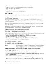
... disabled and will not be any configuration settings, you try to access the Setup Utility program. From the Setup Utility program menu, select Security. 3. From the Setup Utility program menu, select Devices ® SATA Drives Setup ® SATA 1 and press Enter. 3. Return to a device. Start the Setup Utility program (see Chapter 6 "Using the Setup Utility" on the right side of the screen. SATA 1 OnBoard Floppy Controller When this feature is displayed each time you must use your need, select Set User Passwords or Set Administrator Passwords. 4. Setting...
... disabled and will not be any configuration settings, you try to access the Setup Utility program. From the Setup Utility program menu, select Security. 3. From the Setup Utility program menu, select Devices ® SATA Drives Setup ® SATA 1 and press Enter. 3. Return to a device. Start the Setup Utility program (see Chapter 6 "Using the Setup Utility" on the right side of the screen. SATA 1 OnBoard Floppy Controller When this feature is displayed each time you must use your need, select Set User Passwords or Set Administrator Passwords. 4. Setting...
Hardware Maintenance Manual
Page 51
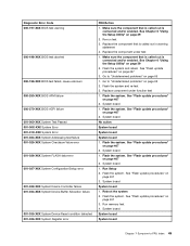
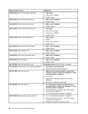
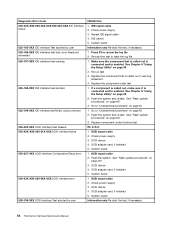
... is connected and/or enabled. See Chapter 6 "Using the Setup Utility" on page 467 3. Replace component under test 1. Flash the system. Flash the system. Flash the system. See "Flash update procedures" on page 39 2. See Chapter 6 "Using the Setup Utility" on page 467 3. Flash the system. System board 1. Diagnostic Error Code 000-197-XXX BIOS test warning 000-198-XXX BIOS test aborted 000-199-XXX BIOS test failed, cause unknown 000-250-XXX BIOS APM failure 000...
... is connected and/or enabled. See Chapter 6 "Using the Setup Utility" on page 467 3. Replace component under test 1. Flash the system. Flash the system. Flash the system. See "Flash update procedures" on page 39 2. See Chapter 6 "Using the Setup Utility" on page 467 3. Flash the system. System board 1. Diagnostic Error Code 000-197-XXX BIOS test warning 000-198-XXX BIOS test aborted 000-199-XXX BIOS test failed, cause unknown 000-250-XXX BIOS APM failure 000...
Hardware Maintenance Manual
Page 52
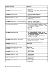
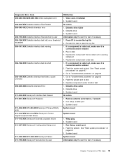
... Setup Utility" on page 467 2. See "Flash update procedures" on IRQ5 2. System board 1. Device on page 467 3. System board 1. System board Information only Re-start the test to "Undetermined problems" on system and re-test 2. Replace the component under function test System board System board System board 1. Go to review the log file 2. Flash the system. If a component is called out is connected and/or enabled. Diagnostic Error Code 001-038-XXX System Extension failure...
... Setup Utility" on page 467 2. See "Flash update procedures" on IRQ5 2. System board 1. Device on page 467 3. System board 1. System board Information only Re-start the test to "Undetermined problems" on system and re-test 2. Replace the component under function test System board System board System board 1. Go to review the log file 2. Flash the system. If a component is called out is connected and/or enabled. Diagnostic Error Code 001-038-XXX System Extension failure...
Hardware Maintenance Manual
Page 54
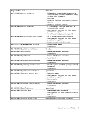
... system and re-test. Video card, if installed 2. See Chapter 6 "Using the Setup Utility" on page 65 1. Video Ram 2. System board 1. Video card, if installed 4. System board 1. Video card, if installed 2. Go to "Undetermined problems" on page 39 2. Diagnostic Error Code 005-016-XXX Video Simple Pattern test failure 005-024-XXX Video Addressing test failure 005-025-XXX Video Checksum Value error 005-027-XXX Video Configuration/Setup error 005-031-XXX Video Device Cable failure 005-032-XXX Video Device Controller failure 005-036-XXX Video Register error 005-038-XXX...
... system and re-test. Video card, if installed 2. See Chapter 6 "Using the Setup Utility" on page 65 1. Video Ram 2. System board 1. Video card, if installed 4. System board 1. Video card, if installed 2. Go to "Undetermined problems" on page 39 2. Diagnostic Error Code 005-016-XXX Video Simple Pattern test failure 005-024-XXX Video Addressing test failure 005-025-XXX Video Checksum Value error 005-027-XXX Video Configuration/Setup error 005-031-XXX Video Device Cable failure 005-032-XXX Video Device Controller failure 005-036-XXX Video Register error 005-038-XXX...
Hardware Maintenance Manual
Page 55
... Serial port Interface Test Passed 011-001-XXX Serial port Presence 011-002-XXX 011-003-XXX Serial port Timeout/Parity error 011-013-XXX 011-014-XXX Serial port Control Signal/Loopback test failure 011-015-XXX Serial port External Loopback failure 011-027-XXX Serial port Configuration/Setup error 011-03X-XXX 011-04X-XXX Serial port failure 011-195-XXX Serial port Test aborted by user FRU/Action 1. Replace the component under function test 1. System board 1. Video card, if installed 2. Go to reset...
... Serial port Interface Test Passed 011-001-XXX Serial port Presence 011-002-XXX 011-003-XXX Serial port Timeout/Parity error 011-013-XXX 011-014-XXX Serial port Control Signal/Loopback test failure 011-015-XXX Serial port External Loopback failure 011-027-XXX Serial port Configuration/Setup error 011-03X-XXX 011-04X-XXX Serial port failure 011-195-XXX Serial port Test aborted by user FRU/Action 1. Replace the component under function test 1. System board 1. Video card, if installed 2. Go to reset...
Hardware Maintenance Manual
Page 57
... test 1. Flash the system and re-test. Run setup and check for conflicts 2. See "Flash update procedures" on page 65 2. External parallel device 2. Remove USB device(s) and re-test 2. System board System board 1. Replace the component under function test 1. System board Information only Re-start the test, if necessary Chapter 7 Symptom-to "Undetermined problems" on page 467 3. Diagnostic Error Code 014-197-XXX Parallel port test warning 014-198-XXX Parallel port test aborted 014-199-XXX Parallel port test...
... test 1. Flash the system and re-test. Run setup and check for conflicts 2. See "Flash update procedures" on page 65 2. External parallel device 2. Remove USB device(s) and re-test 2. System board System board 1. Replace the component under function test 1. System board Information only Re-start the test, if necessary Chapter 7 Symptom-to "Undetermined problems" on page 467 3. Diagnostic Error Code 014-197-XXX Parallel port test warning 014-198-XXX Parallel port test aborted 014-199-XXX Parallel port test...
Hardware Maintenance Manual
Page 59
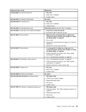
... 4. Check power supply voltages 3. IDE device 5. Flash the system and re-test. Press F3 to "Undetermined problems" on page 467 3. Go to review the log file 2. Riser card, if installed 3. Flash the system. System board Information only Re-start the test to reset the log file 1. Re-start the test, if necessary 1. Flash the system and re-test. IDE signal cable 2. Diagnostic Error Code 018-250-XXX PCI Card Services error 020-000-XXX PCI Interface Test Passed...
... 4. Check power supply voltages 3. IDE device 5. Flash the system and re-test. Press F3 to "Undetermined problems" on page 467 3. Go to review the log file 2. Riser card, if installed 3. Flash the system. System board Information only Re-start the test to reset the log file 1. Re-start the test, if necessary 1. Flash the system and re-test. IDE signal cable 2. Diagnostic Error Code 018-250-XXX PCI Card Services error 020-000-XXX PCI Interface Test Passed...
Hardware Maintenance Manual
Page 60
... board 1. Flash the system. SCSI device 4. SCSI signal cable 2. System board Information only Re-start the test, if necessary 1. Re-start the test to review the log file 2. Re-run test 3. If a component is called out is connected and/or enabled. Flash the system and re-test. Flash the system and re-test. Replace component under test 1. SCSI adapter card, if installed 5. Diagnostic Error Code 025-02X-XXX 025-03X-XXX 025-04X-XXX IDE Interface failure...
... board 1. Flash the system. SCSI device 4. SCSI signal cable 2. System board Information only Re-start the test, if necessary 1. Re-start the test to review the log file 2. Re-run test 3. If a component is called out is connected and/or enabled. Flash the system and re-test. Flash the system and re-test. Replace component under test 1. SCSI adapter card, if installed 5. Diagnostic Error Code 025-02X-XXX 025-03X-XXX 025-04X-XXX IDE Interface failure...
Hardware Maintenance Manual
Page 68
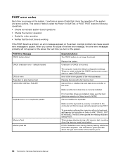
... hard disk drive controller or the drive. This series of the memory error. 62 ThinkCentre Hardware Maintenance Manual This message displays during memory testing, additional information appears. If POST detects an error during a full memory test, counting down the memory areas being tested. This information gives specifics about the type and location of tests is no keyboard present Memory Test: Memory test fail Description/Action The CMOS battery is called the Power-On Self-Test, or POST. POST Error Message CMOS battery failed CMOS checksum error - This error...
... hard disk drive controller or the drive. This series of the memory error. 62 ThinkCentre Hardware Maintenance Manual This message displays during memory testing, additional information appears. If POST detects an error during a full memory test, counting down the memory areas being tested. This information gives specifics about the type and location of tests is no keyboard present Memory Test: Memory test fail Description/Action The CMOS battery is called the Power-On Self-Test, or POST. POST Error Message CMOS battery failed CMOS checksum error - This error...

Hardware Maintenance Manual
Page 69
... server 1. System Board 2. Run the Memory tests 2. Memory Module 3. The BIOS was unable to -FRU Index 63 Ensure that the operating system settings are set to the computer. Ensure Wake On LAN feature is enabled for RPL 3. See "Hard disk drive boot error" on page 43. 1. Diskette Drive Cable Flashing cursor with an otherwise blank display. 1. Ensure that network adapter is enabled in Setup/Configuration (see "Starting the Setup Utility program" on LAN® 3. Network adapter (Advise network administrator of new MAC address) Dead computer. Make...
... server 1. System Board 2. Run the Memory tests 2. Memory Module 3. The BIOS was unable to -FRU Index 63 Ensure that the operating system settings are set to the computer. Ensure Wake On LAN feature is enabled for RPL 3. See "Hard disk drive boot error" on page 43. 1. Diskette Drive Cable Flashing cursor with an otherwise blank display. 1. Ensure that network adapter is enabled in Setup/Configuration (see "Starting the Setup Utility program" on LAN® 3. Network adapter (Advise network administrator of new MAC address) Dead computer. Make...

Hardware Maintenance Manual
Page 70
... 2. Video adapter (if present) 3. System Board 3. System Board Serial or parallel port device failure (adapter port) 1. Diskette Drive Cable 4. Network Adapter Intensity or color varies from the hard disk with a known-good diagnostics diskette in the first 3.5-inch diskette drive. 1. See "Hard disk drive boot error" on , 1. System Board No power or fan not running 1. Cable 4. Cable 4. System Board Some or all keys on the keyboard do not work 1. RPL, check startup sequence: a. Display or illegible display) 2. System Board 64 ThinkCentre Hardware Maintenance Manual
... 2. Video adapter (if present) 3. System Board 3. System Board Serial or parallel port device failure (adapter port) 1. Diskette Drive Cable 4. Network Adapter Intensity or color varies from the hard disk with a known-good diagnostics diskette in the first 3.5-inch diskette drive. 1. See "Hard disk drive boot error" on , 1. System Board No power or fan not running 1. Cable 4. Cable 4. System Board Some or all keys on the keyboard do not work 1. RPL, check startup sequence: a. Display or illegible display) 2. System Board 64 ThinkCentre Hardware Maintenance Manual
Hardware Maintenance Manual
Page 71
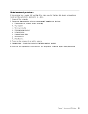
... drive 3. External devices (modem, printer, or mouse) b. External Cache RAM g. Repeat steps 1 through 3 until you find the failing device or adapter. Memory modules d. External Cache f. Hard disk drive h. Undetermined problems If this computer has a parallel ATA hard disk drive, make sure that the hard disk drive is jumpered as a master and the optical drive is jumpered as a slave. 1. Remove or disconnect the following components (if installed) one at a time. Chapter 7 Symptom-to re-test the system. 4. Extended video memory e. Any adapters c. Power...
... drive 3. External devices (modem, printer, or mouse) b. External Cache RAM g. Repeat steps 1 through 3 until you find the failing device or adapter. Memory modules d. External Cache f. Hard disk drive h. Undetermined problems If this computer has a parallel ATA hard disk drive, make sure that the hard disk drive is jumpered as a master and the optical drive is jumpered as a slave. 1. Remove or disconnect the following components (if installed) one at a time. Chapter 7 Symptom-to re-test the system. 4. Extended video memory e. Any adapters c. Power...
Hardware Maintenance Manual
Page 96
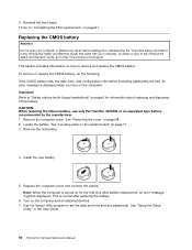
... computer cover, and connect the cables. Use the Setup Utility program to "Completing the FRU replacement" on how to remove and replace the CMOS battery. An error message is normal after battery replacement, an error message might be displayed. Install the new battery. 5. Important Refer to "Safety notices (multi-lingual translations)" on page 6 for the first time after replacing the battery. 6. See "Locating parts on the system board" on the computer and all attached devices. 7. Turn...
... computer cover, and connect the cables. Use the Setup Utility program to "Completing the FRU replacement" on how to remove and replace the CMOS battery. An error message is normal after battery replacement, an error message might be displayed. Install the new battery. 5. Important Refer to "Safety notices (multi-lingual translations)" on page 6 for the first time after replacing the battery. 6. See "Locating parts on the system board" on the computer and all attached devices. 7. Turn...
Hardware Maintenance Manual
Page 105
See "Locating parts on the system board" on the computer and all power supply cables from the system board. Remove the old battery. 4. Turn on page 95. 3. To remove or replace the power supply: 1. Install the new battery. 5. Replace the computer cover, and connect the cables Note: When the computer is normal after battery replacement, an error message might be displayed. Remove the drive bay assembly. 2. Use the Setup Utility program to remove and replace the power supply. See "Removing the cover" on for the first time...
See "Locating parts on the system board" on the computer and all power supply cables from the system board. Remove the old battery. 4. Turn on page 95. 3. To remove or replace the power supply: 1. Install the new battery. 5. Replace the computer cover, and connect the cables Note: When the computer is normal after battery replacement, an error message might be displayed. Remove the drive bay assembly. 2. Use the Setup Utility program to remove and replace the power supply. See "Removing the cover" on for the first time...

Hardware Maintenance Manual
Page 106
... power supply cable through the cable clamps underneath the hard disk drive and reconnect all power supply cables to let the computer cool before opening the computer cover. 100 ThinkCentre Hardware Maintenance Manual Install the hard disk drive. Reinstall the front bezel. 16. Turn off the computer and wait three to five minutes to the system board. 12. Remove the screws that secure the system board to the chassis and slide the system board...
... power supply cable through the cable clamps underneath the hard disk drive and reconnect all power supply cables to let the computer cool before opening the computer cover. 100 ThinkCentre Hardware Maintenance Manual Install the hard disk drive. Reinstall the front bezel. 16. Turn off the computer and wait three to five minutes to the system board. 12. Remove the screws that secure the system board to the chassis and slide the system board...


