Hardware Maintenance Manual
Page 5
... the diagnostic programs . 39 Running tests 39 Viewing the test log 41 © Copyright Lenovo 2008, 2012 Chapter 6. Diagnostic programs . . . 37 Lenovo ThinkVantage Toolbox 37 Lenovo Solution Center 37 Lenovo System Toolbox 38 PC-Doctor for Rescue and Recovery 38 PC-Doctor for DOS 38 Creating... cover 73 Locating components 75 Locating parts on the system board 76 Removing and reinstalling the front bezel . . . . 77 Replacing a memory module 78 Replacing the power supply 79 Replacing the heat sink and fan assembly . . . . 80 Replacing the microprocessor 81 Replacing the ...
... the diagnostic programs . 39 Running tests 39 Viewing the test log 41 © Copyright Lenovo 2008, 2012 Chapter 6. Diagnostic programs . . . 37 Lenovo ThinkVantage Toolbox 37 Lenovo Solution Center 37 Lenovo System Toolbox 38 PC-Doctor for Rescue and Recovery 38 PC-Doctor for DOS 38 Creating... cover 73 Locating components 75 Locating parts on the system board 76 Removing and reinstalling the front bezel . . . . 77 Replacing a memory module 78 Replacing the power supply 79 Replacing the heat sink and fan assembly . . . . 80 Replacing the microprocessor 81 Replacing the ...
Hardware Maintenance Manual
Page 6
... cover 107 Accessing the system board components and drives 108 Locating components 109 Locating parts on the system board 110 Replacing the battery 110 Replacing a memory module 112 Replacing an adapter card 113 Replacing the power supply 115 Replacing the heat sink and fan assembly . . . . 117 Replacing the microprocessor 118 Replacing...
... cover 107 Accessing the system board components and drives 108 Locating components 109 Locating parts on the system board 110 Replacing the battery 110 Replacing a memory module 112 Replacing an adapter card 113 Replacing the power supply 115 Replacing the heat sink and fan assembly . . . . 117 Replacing the microprocessor 118 Replacing...
Hardware Maintenance Manual
Page 56
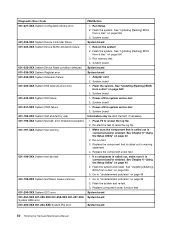
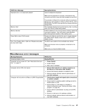
...) BIOS from a disc" on page 560 2. See "Updating (flashing) BIOS from a disc" on page 560 3. See "Updating (flashing) BIOS from a disc" on page 560 3. Run memory test 4. See "Updating (flashing) BIOS from a disc" on page 560 2. Flash the system. Flash the system. Check/Verify Check the following index, X can represent any...
...) BIOS from a disc" on page 560 2. See "Updating (flashing) BIOS from a disc" on page 560 3. See "Updating (flashing) BIOS from a disc" on page 560 3. Run memory test 4. See "Updating (flashing) BIOS from a disc" on page 560 2. Flash the system. Flash the system. Check/Verify Check the following index, X can represent any...
Hardware Maintenance Manual
Page 58
...-XXX 001-264-XXX System IRQ error FRU/Action 1. Reboot the system 2. Flash the system. See "Updating (flashing) BIOS from a disc" on page 560 3. Run memory test 4. Power-off /on page 560 3. Re-start the test, if necessary 1. Make sure the component that is called out in warning statement 4. See Chapter...
...-XXX 001-264-XXX System IRQ error FRU/Action 1. Reboot the system 2. Flash the system. See "Updating (flashing) BIOS from a disc" on page 560 3. Run memory test 4. Power-off /on page 560 3. Re-start the test, if necessary 1. Make sure the component that is called out in warning statement 4. See Chapter...
Hardware Maintenance Manual
Page 63
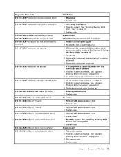
... under function test 1. See "Updating (flashing) BIOS from a disc" on page 43 2. System board No action 1. System board 1. Flash the system. Reboot the system 2. Run memory test 4. System board System board Information only Re-start the test to reset the log file 1. Go to review the log file 2. Replace component under...
... under function test 1. See "Updating (flashing) BIOS from a disc" on page 43 2. System board No action 1. System board 1. Flash the system. Reboot the system 2. Run memory test 4. System board System board Information only Re-start the test to reset the log file 1. Go to review the log file 2. Replace component under...
Hardware Maintenance Manual
Page 72
System board No action 1. Replace the memory module called out by the test 2. System board 3. Check power supply voltages 3. Hard Disk drive (SCSI) 5. Microprocessor 4. Flash system 2. System board No action 1. Diskette Drive ...-XXX Asset Security Test Passed 185-XXX-XXX Asset Security failure 185-278-XXX Asset Security Chassis Intrusion 201-000-XXX System Memory Test Passed 201-XXX-XXX System Memory error 202-000-XXX System Cache Test Passed 202-XXX-XXX System Cache error 206-000-XXX Diskette Drive Test Passed 206...
System board No action 1. Replace the memory module called out by the test 2. System board 3. Check power supply voltages 3. Hard Disk drive (SCSI) 5. Microprocessor 4. Flash system 2. System board No action 1. Diskette Drive ...-XXX Asset Security Test Passed 185-XXX-XXX Asset Security failure 185-278-XXX Asset Security Chassis Intrusion 201-000-XXX System Memory Test Passed 201-XXX-XXX System Memory error 202-000-XXX System Cache Test Passed 202-XXX-XXX System Cache error 206-000-XXX Diskette Drive Test Passed 206...
Hardware Maintenance Manual
Page 74
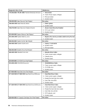
...from a POST/BIOS update failure" on page 43. 2. Perform the following operations. • Checks some basic system-board operations • Checks the memory operation • Starts the video operation • Verifies that check the operation of the system and some options. When you correct the cause of ...Checksum of CMOS is correctly installed. Make sure the hard disk drive is incorrect. Replace the system board. Pressing Esc skips the full memory test Cannot find or initialize the hard disk drive controller or the drive. POST error codes Each time you turn on the system,...
...from a POST/BIOS update failure" on page 43. 2. Perform the following operations. • Checks some basic system-board operations • Checks the memory operation • Starts the video operation • Verifies that check the operation of the system and some options. When you correct the cause of ...Checksum of CMOS is correctly installed. Make sure the hard disk drive is incorrect. Replace the system board. Pressing Esc skips the full memory test Cannot find or initialize the hard disk drive controller or the drive. POST error codes Each time you turn on the system,...
Hardware Maintenance Manual
Page 75
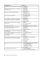
...Setup/Configuration (see "Starting the Setup Utility program" on page 47. 1. If POST detects an error during a full memory test, counting down the memory areas being tested. Miscellaneous error messages Message/Symptom FRU/Action Changing display colors Display/Monitor Computer will not RPL from server... 1. Ensure that no keyboard present Memory Test: Memory test fail Press TAB to HALT ON ALL, BUT KEYBOARD. Ensure Wake on LAN feature is properly connected to the computer...
...Setup/Configuration (see "Starting the Setup Utility program" on page 47. 1. If POST detects an error during a full memory test, counting down the memory areas being tested. Miscellaneous error messages Message/Symptom FRU/Action Changing display colors Display/Monitor Computer will not RPL from server... 1. Ensure that no keyboard present Memory Test: Memory test fail Press TAB to HALT ON ALL, BUT KEYBOARD. Ensure Wake on LAN feature is properly connected to the computer...
Hardware Maintenance Manual
Page 76
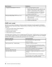
...1. Check the network adapter LED status 68 ThinkCentre Hardware Maintenance Manual Diskette Drive 2. Primary Hard Disk Drive 3. Run the Memory tests 2. System Board "Insert a Diskette" icon appears with a known-good diagnostics diskette in -use light remains on or...FRU/Action Dead computer. Power Supply 2. Diskette Drive Cable Flashing cursor with a known-good diagnostic diskette. 1. Hard Disk Drive Cable Incorrect memory size during POST 1. System Board 2. Network Adapter Intensity or color varies from its own hard 1. Display 2. Video adapter (if present...
...1. Check the network adapter LED status 68 ThinkCentre Hardware Maintenance Manual Diskette Drive 2. Primary Hard Disk Drive 3. Run the Memory tests 2. System Board "Insert a Diskette" icon appears with a known-good diagnostics diskette in -use light remains on or...FRU/Action Dead computer. Power Supply 2. Diskette Drive Cable Flashing cursor with a known-good diagnostic diskette. 1. Hard Disk Drive Cable Incorrect memory size during POST 1. System Board 2. Network Adapter Intensity or color varies from its own hard 1. Display 2. Video adapter (if present...
Hardware Maintenance Manual
Page 77
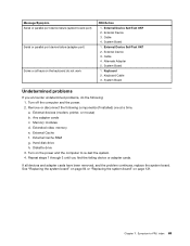
...RAM g. Hard disk drive h. System Board 1. Cable 4. System Board Undetermined problems If you find the failing device or adapter cards. Memory modules d. Symptom-to re-test the system. 4. Keyboard 2. Turn on the power and the computer to -FRU index 69 External ...on the keyboard do the following components (if installed) one at a time. External Device Self-Test OK? 2. Diskette drive 3. Extended video memory e. External Cache f. If all keys on page 121. Cable 4. Alternate Adapter 5. Repeat steps 1 through 3 until you encounter undetermined problems...
...RAM g. Hard disk drive h. System Board 1. Cable 4. System Board Undetermined problems If you find the failing device or adapter cards. Memory modules d. Symptom-to re-test the system. 4. Keyboard 2. Turn on the power and the computer to -FRU index 69 External ...on the keyboard do the following components (if installed) one at a time. External Device Self-Test OK? 2. Diskette drive 3. Extended video memory e. External Cache f. If all keys on page 121. Cable 4. Alternate Adapter 5. Repeat steps 1 through 3 until you encounter undetermined problems...
Hardware Maintenance Manual
Page 83
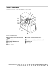
Component locations 1 Microprocessor, heat sink, and heat sink fan assembly 2 Memory slots (4) 3 PCI Express x1 adapter card slot 4 Adapter card 5 Adapter card slot 6 PCI Express x16 graphics adapter card slot 7 Cover presence switch (also called intrusion ...
Component locations 1 Microprocessor, heat sink, and heat sink fan assembly 2 Memory slots (4) 3 PCI Express x1 adapter card slot 4 Adapter card 5 Adapter card slot 6 PCI Express x16 graphics adapter card slot 7 Cover presence switch (also called intrusion ...
Hardware Maintenance Manual
Page 84
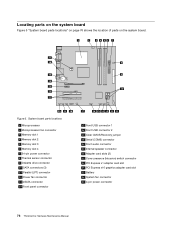
System board parts locations 1 Microprocessor 2 Microprocessor fan connector 3 Memory slot 1 4 Memory slot 2 5 Memory slot 3 6 Memory slot 4 7 24-pin power connector 8 Thermal sensor connector 9 Diskette drive connector 10 SATA connectors (3) 11 Parallel (LPT) connector 12 Power fan connector 13 eSATA connector ...
System board parts locations 1 Microprocessor 2 Microprocessor fan connector 3 Memory slot 1 4 Memory slot 2 5 Memory slot 3 6 Memory slot 4 7 24-pin power connector 8 Thermal sensor connector 9 Diskette drive connector 10 SATA connectors (3) 11 Parallel (LPT) connector 12 Power fan connector 13 eSATA connector ...
Hardware Maintenance Manual
Page 86
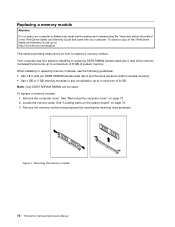
...2. Note: Only DDR3 SDRAM DIMMs can be used. Remove the computer cover. Locate the memory slots. To replace a memory module: 1. Removing the memory module 78 ThinkCentre Hardware Maintenance Manual Replacing a memory module Attention Do not open your computer. To obtain a copy of the ThinkCentre Safety and ...Warranty Guide, go to: http://www.lenovo.com/support This section provides instructions on how to a maximum of 8 GB of 8 GB. Figure 7. Remove the memory module being replaced by opening the retaining clips as shown. Your computer has...
...2. Note: Only DDR3 SDRAM DIMMs can be used. Remove the computer cover. Locate the memory slots. To replace a memory module: 1. Removing the memory module 78 ThinkCentre Hardware Maintenance Manual Replacing a memory module Attention Do not open your computer. To obtain a copy of the ThinkCentre Safety and ...Warranty Guide, go to: http://www.lenovo.com/support This section provides instructions on how to a maximum of 8 GB of 8 GB. Figure 7. Remove the memory module being replaced by opening the retaining clips as shown. Your computer has...
Hardware Maintenance Manual
Page 87
... on its side and remove the four screws at the rear of the ThinkCentre Safety and Warranty Guide, go to: http://www.lenovo.com/support This section provides instructions on how to "Completing the FRU replacement" on the system board. Hazardous voltage, current, and... energy levels are no serviceable parts inside any component that secure the power supply. Position the replacement memory module over the memory slot. Figure 8. Replacing FRUs (Machine Types: 3063, 3231, 3285, 4084, 4085, 4086, 4087, 6138, 6209, 6239, 6302, 7188...
... on its side and remove the four screws at the rear of the ThinkCentre Safety and Warranty Guide, go to: http://www.lenovo.com/support This section provides instructions on how to "Completing the FRU replacement" on the system board. Hazardous voltage, current, and... energy levels are no serviceable parts inside any component that secure the power supply. Position the replacement memory module over the memory slot. Figure 8. Replacing FRUs (Machine Types: 3063, 3231, 3285, 4084, 4085, 4086, 4087, 6138, 6209, 6239, 6302, 7188...
Hardware Maintenance Manual
Page 93
Remove the memory modules from the failing system board and install it in the same position on the new system board. See "Replacing the heat sink and fan ... power and signal cables to protect the pins during shipping and handling. See "Locating parts on the system board" on page 78. 10. See "Replacing a memory module" on page 76. 7. To install the microprocessor socket cover: Chapter 8. Replacing FRUs (Machine Types: 3063, 3231, 3285, 4084, 4085, 4086, 4087, 6138, 6209, 6239...
Remove the memory modules from the failing system board and install it in the same position on the new system board. See "Replacing the heat sink and fan ... power and signal cables to protect the pins during shipping and handling. See "Locating parts on the system board" on page 78. 10. See "Replacing a memory module" on page 76. 7. To install the microprocessor socket cover: Chapter 8. Replacing FRUs (Machine Types: 3063, 3231, 3285, 4084, 4085, 4086, 4087, 6138, 6209, 6239...
Hardware Maintenance Manual
Page 94
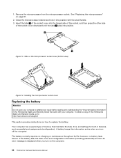
...battery. A battery keeps this information active when you turn off the computer. Tabs on page 81. 2. Your computer has a special type of memory that came with the small handle. 3. If the battery fails, the date, time, and configuration information (including passwords) are lost. Remove ... side of the socket, and then press the other side of the ThinkCentre Safety and Warranty Guide, go to: http://www.lenovo.com/support This section provides instructions on the computer. 86 ThinkCentre Hardware Maintenance Manual Figure 13. The battery normally requires no battery lasts...
...battery. A battery keeps this information active when you turn off the computer. Tabs on page 81. 2. Your computer has a special type of memory that came with the small handle. 3. If the battery fails, the date, time, and configuration information (including passwords) are lost. Remove ... side of the socket, and then press the other side of the ThinkCentre Safety and Warranty Guide, go to: http://www.lenovo.com/support This section provides instructions on the computer. 86 ThinkCentre Hardware Maintenance Manual Figure 13. The battery normally requires no battery lasts...
Hardware Maintenance Manual
Page 117
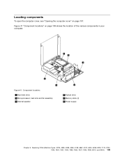
Figure 41 "Component locations" on page 107. Figure 41. Component locations 1 Hard disk drive 2 Microprocessor, heat sink and fan assembly 3 Internal speaker 4 Optical drive 5 Memory slots (4) 6 Power supply Chapter 9. Replacing FRUs (Machine Types: 3379, 4083, 4088, 4099, 4138, 5897, 6137, 6234, 6258, 6303, 7174, 7220, 7346, 7354, 7357, 7360, 7483, 7582, 7627, 7630, 7638, 8910, and 9964.) 109 Locating components To open the computer cover, see "Opening the computer cover" on page 109 shows the location of the various components in your computer.
Figure 41 "Component locations" on page 107. Figure 41. Component locations 1 Hard disk drive 2 Microprocessor, heat sink and fan assembly 3 Internal speaker 4 Optical drive 5 Memory slots (4) 6 Power supply Chapter 9. Replacing FRUs (Machine Types: 3379, 4083, 4088, 4099, 4138, 5897, 6137, 6234, 6258, 6303, 7174, 7220, 7346, 7354, 7357, 7360, 7483, 7582, 7627, 7630, 7638, 8910, and 9964.) 109 Locating components To open the computer cover, see "Opening the computer cover" on page 109 shows the location of the various components in your computer.
Hardware Maintenance Manual
Page 118
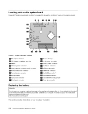
...3 Battery 4 Internal speaker connector 5 Cover presence (Intrusion) switch connector 6 Microprocessor fan connector 7 Thermal sensor connector 8 Microprocessor 9 4-pin power connector 10 Front panel connector 11 Memory slots (4) 12 24-pin power connector 13 Serial (COM 2) connector 14 Front audio connector 15 SATA connectors (2) 16 System fan connector 17 Front USB connector... Figure 42 "System board parts locations" on page 110 shows the location of the ThinkCentre Safety and Warranty Guide, go to: http://www.lenovo.com/support This section provides instructions on the system board.
...3 Battery 4 Internal speaker connector 5 Cover presence (Intrusion) switch connector 6 Microprocessor fan connector 7 Thermal sensor connector 8 Microprocessor 9 4-pin power connector 10 Front panel connector 11 Memory slots (4) 12 24-pin power connector 13 Serial (COM 2) connector 14 Front audio connector 15 SATA connectors (2) 16 System fan connector 17 Front USB connector... Figure 42 "System board parts locations" on page 110 shows the location of the ThinkCentre Safety and Warranty Guide, go to: http://www.lenovo.com/support This section provides instructions on the system board.
Hardware Maintenance Manual
Page 119
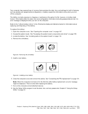
..." on page 43. Access the system board. Remove the old battery. Close the computer cover and connect the cables. Your computer has a special type of memory that maintains the date, time, and settings for built-in the ThinkCentre Safety and Warranty Guide for the first time after replacing the battery. 7. Turn...
..." on page 43. Access the system board. Remove the old battery. Close the computer cover and connect the cables. Your computer has a special type of memory that maintains the date, time, and settings for built-in the ThinkCentre Safety and Warranty Guide for the first time after replacing the battery. 7. Turn...
Hardware Maintenance Manual
Page 120
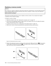
... computer can support a maximum of the ThinkCentre Safety and Warranty Guide, go to: http://www.lenovo.com/support This section provides instructions on how to the system board. Locate the memory slots. Remove the memory module being replaced by opening the retaining clips as shown. Position the replacement... straight down into the slot until the retaining clips close. 112 ThinkCentre Hardware Maintenance Manual Removing the memory module 5. Replacing a memory module Attention Do not open your computer or attempt any repair before reading and understanding the "Important safety information...
... computer can support a maximum of the ThinkCentre Safety and Warranty Guide, go to: http://www.lenovo.com/support This section provides instructions on how to the system board. Locate the memory slots. Remove the memory module being replaced by opening the retaining clips as shown. Position the replacement... straight down into the slot until the retaining clips close. 112 ThinkCentre Hardware Maintenance Manual Removing the memory module 5. Replacing a memory module Attention Do not open your computer or attempt any repair before reading and understanding the "Important safety information...


