UDS2100 - Quick Start Guide
Page 6
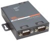
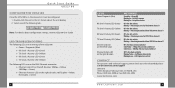
Select one of the UDS2100: ‹ Power / Diagnostic (Blue) ‹ RX Serial 1 Activity LED (Green) ‹ TX Serial 1 Activity LED (Yellow) ‹ RX Serial 2 Activity LED (Green) ‹ TX Serial 2 Activity LED (Yellow) ... Yellow = Half Duplex data activity Blinking Green = Full Duplex data activity CONTACT For questions and technical support, please check our online knowledge base at www.lantronix.com/support Lantronix 15353 Barranca Parkway, Irvine, CA 92618, USA Phone: (949) 453-3990 or Fax: (949) 453-3995 www...
Select one of the UDS2100: ‹ Power / Diagnostic (Blue) ‹ RX Serial 1 Activity LED (Green) ‹ TX Serial 1 Activity LED (Yellow) ‹ RX Serial 2 Activity LED (Green) ‹ TX Serial 2 Activity LED (Yellow) ... Yellow = Half Duplex data activity Blinking Green = Full Duplex data activity CONTACT For questions and technical support, please check our online knowledge base at www.lantronix.com/support Lantronix 15353 Barranca Parkway, Irvine, CA 92618, USA Phone: (949) 453-3990 or Fax: (949) 453-3995 www...
UDS2100 - User Guide
Page 6
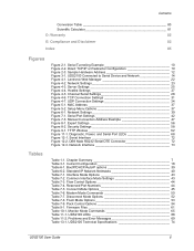
Direct TCP/IP or Redirector Configuration 10 Figure 2-3. Manual Connection Address Example 47 Figure 8-1. Diagnostic, Power, and Serial Port LEDs 68 Figure 12-1. Flush Mode Options 53 Table 7-9. UDS2100 LEDs 68 Table 11-2. MAC Address 37 Figure 5-2. Security Settings 58 Figure 9-1. DB9 Male RS232 Serial DTE Connector 72... and Disclaimer 83 Index 85 Figures Tables Figure 2-1. Network Settings 39 Figure 7-1. Expert Settings 56 Figure 8-2. Interface Mode Options 43 Table 7-2. Lantronix Web Manager 22 Figure 4-2. Modem Mode Commands 50 Table 7-7.
Direct TCP/IP or Redirector Configuration 10 Figure 2-3. Manual Connection Address Example 47 Figure 8-1. Diagnostic, Power, and Serial Port LEDs 68 Figure 12-1. Flush Mode Options 53 Table 7-9. UDS2100 LEDs 68 Table 11-2. MAC Address 37 Figure 5-2. Security Settings 58 Figure 9-1. DB9 Male RS232 Serial DTE Connector 72... and Disclaimer 83 Index 85 Figures Tables Figure 2-1. Network Settings 39 Figure 7-1. Expert Settings 56 Figure 8-2. Interface Mode Options 43 Table 7-2. Lantronix Web Manager 22 Figure 4-2. Modem Mode Commands 50 Table 7-7.

UDS2100 - User Guide
Page 20
.... Connect a console terminal or a PC running a terminal emulation program to save and exit Setup Mode. Select 9 to the unit's serial port. UDS2100 User Guide 20 The Setup Mode window displays. 2. 3: Getting Started Note: Alternatively, to hold down the x key at the terminal (or emulation)... while powering up , the self-test begins and the red Diagnostic LED starts blinking. Click the Telnet Configuration tab. After power-up the unit. 3. To enter Setup Mode, cycle the unit's power (power off...
.... Connect a console terminal or a PC running a terminal emulation program to save and exit Setup Mode. Select 9 to the unit's serial port. UDS2100 User Guide 20 The Setup Mode window displays. 2. 3: Getting Started Note: Alternatively, to hold down the x key at the terminal (or emulation)... while powering up , the self-test begins and the red Diagnostic LED starts blinking. Click the Telnet Configuration tab. After power-up the unit. 3. To enter Setup Mode, cycle the unit's power (power off...

UDS2100 - User Guide
Page 64
... using a Telnet connection: 1. Monitor Mode Commands The following commands are two ways to the configuration port (9999). 2. Note: All commands must be in Monitor Mode. UDS2100 User Guide 64 Follow the same steps used for setting the serial configuration parameters (see Serial Port on page 37). 2. 10: Monitor Mode Monitor Mode...
... using a Telnet connection: 1. Monitor Mode Commands The following commands are two ways to the configuration port (9999). 2. Note: All commands must be in Monitor Mode. UDS2100 User Guide 64 Follow the same steps used for setting the serial configuration parameters (see Serial Port on page 37). 2. 10: Monitor Mode Monitor Mode...

UDS2100 - User Guide
Page 65
...Sf GM SS SA NS co Table 10-1. Network Connection Shows the unit's current IP address, gateway, subnet mask, and DNS server. Quit Exits diagnostics mode. If the BSS does not broadcast its SSID, only the BSSID and RSSI are not overwritten). Scan Initiates a wireless scan if the wireless ... information on the device. ARP Table Shows the unit's ARP table entries. Get configuration from memory page Gets a memory page of the DNS Server UDS2100 User Guide 65 Set IP address, host bits, gateway, and DNS server IP Example: co 192.168.0.10 8 192.168.0.1 10001 192.168...
...Sf GM SS SA NS co Table 10-1. Network Connection Shows the unit's current IP address, gateway, subnet mask, and DNS server. Quit Exits diagnostics mode. If the BSS does not broadcast its SSID, only the BSSID and RSSI are not overwritten). Scan Initiates a wireless scan if the wireless ... information on the device. ARP Table Shows the unit's ARP table entries. Get configuration from memory page Gets a memory page of the DNS Server UDS2100 User Guide 65 Set IP address, host bits, gateway, and DNS server IP Example: co 192.168.0.10 8 192.168.0.1 10001 192.168...

UDS2100 - User Guide
Page 67
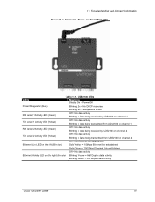
...your unit's IP address is powered up. Note: Some unexplained errors might be caused by duplicate IP addresses on the top of the UDS2100: Power / Diagnostic (Blue) RX Serial 1 Activity LED (Green) TX Serial 1 Activity LED (Yellow) RX Serial 2 Activity LED (Green) TX ...Serial 2 Activity LED (Yellow) The following problems, make sure that the UDS2100 is unique. It helps to connect a terminal to the serial port while diagnosing an error to contact a dealer or Lantronix...
...your unit's IP address is powered up. Note: Some unexplained errors might be caused by duplicate IP addresses on the top of the UDS2100: Power / Diagnostic (Blue) RX Serial 1 Activity LED (Green) TX Serial 1 Activity LED (Yellow) RX Serial 2 Activity LED (Green) TX ...Serial 2 Activity LED (Yellow) The following problems, make sure that the UDS2100 is unique. It helps to connect a terminal to the serial port while diagnosing an error to contact a dealer or Lantronix...
UDS2100 - User Guide
Page 68
... established Off = No data activity Ethernet Activity LED on the right (Bi-color) Blinking Yellow = Half Duplex data activity Blinking Green = Full Duplex data activity UDS2100 User Guide 68 11: Troubleshooting and Contact Information Figure 11-1. Diagnostic, Power, and Serial Port LEDs LEDs Table 11-1.
... established Off = No data activity Ethernet Activity LED on the right (Bi-color) Blinking Yellow = Half Duplex data activity Blinking Green = Full Duplex data activity UDS2100 User Guide 68 11: Troubleshooting and Contact Information Figure 11-1. Diagnostic, Power, and Serial Port LEDs LEDs Table 11-1.

UDS2100 - User Guide
Page 75
... Port Redirector, Windows® 98/NT/2000/XP-based virtual com port software Power 10/100 Mb Link on RJ45 10/100 Activity on RJ45 Diagnostic RX Serial 1 Activity TX Serial 1 Activity RX Serial 2 Activity TX Serial 2 Activity FCC Part 15 Subpart B Class A Radiated Emissions 30MHz - 1000MHz ICES-003 Issue 4 February... Serial Port: 15 KV ESD protection on RS232 and RS422/485 transceivers Power Input: Up to non-repeated 600 W 10/100 usec pulse protection against UDS2100 User Guide 75
... Port Redirector, Windows® 98/NT/2000/XP-based virtual com port software Power 10/100 Mb Link on RJ45 10/100 Activity on RJ45 Diagnostic RX Serial 1 Activity TX Serial 1 Activity RX Serial 2 Activity TX Serial 2 Activity FCC Part 15 Subpart B Class A Radiated Emissions 30MHz - 1000MHz ICES-003 Issue 4 February... Serial Port: 15 KV ESD protection on RS232 and RS422/485 transceivers Power Input: Up to non-repeated 600 W 10/100 usec pulse protection against UDS2100 User Guide 75
