User Guide
Page 2
...: Always turn the display OFF if you leave the room for more than a short period of thunder and lightning, never touch the power cord and signal cable because it can be left unattended for an extended period of power supply you have not been designed for this display, observe the following basic rules for its installation, use, and servicing. When the display is certified...
...: Always turn the display OFF if you leave the room for more than a short period of thunder and lightning, never touch the power cord and signal cable because it can be left unattended for an extended period of power supply you have not been designed for this display, observe the following basic rules for its installation, use, and servicing. When the display is certified...

User Guide
Page 3
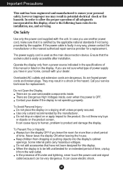
... of your LCD display. If these openings are not covered by placing the display on the screen for your local authority. Cover the openings with your finger for a long time as this display near water such as Red, Green or Blue spots on the screen. If used in which may result in a fire hazard. Make sure to use this may cause some scaled or processed images may...
... of your LCD display. If these openings are not covered by placing the display on the screen for your local authority. Cover the openings with your finger for a long time as this display near water such as Red, Green or Blue spots on the screen. If used in which may result in a fire hazard. Make sure to use this may cause some scaled or processed images may...
User Guide
Page 4
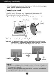
... injure your foot. Make the monitor stand , then pull out the Stop Pin. The product may be removed from the items shown in the picture. Stand Body Side Stop Pin Stand Base FRONT 3. Connecting the Display Before setting up the monitor, ensure that the power to the monitor, the computer system, and other attached devices is pulled up. Assemble the Stand Base into the Stand Body. Do not...
... injure your foot. Make the monitor stand , then pull out the Stop Pin. The product may be removed from the items shown in the picture. Stand Body Side Stop Pin Stand Base FRONT 3. Connecting the Display Before setting up the monitor, ensure that the power to the monitor, the computer system, and other attached devices is pulled up. Assemble the Stand Base into the Stand Body. Do not...
User Guide
Page 5
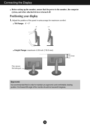
A4 Adjust the position of the panel in order to the monitor, the computer system, and other attached devices is recommended that in various ways for maximum comfort. Positioning your display 1. Tilt Range: -6˚~17˚ Height Range: maximum 4.33 inch (110.0 mm) First, remove the locking pin. 110.0 mm Ergonomic It is turned off. Connecting the Display Before setting up the monitor, ensure that the power to maintain an ergonomic and comfortable viewing position, the forward tilt angle of the monitor should not exceed 5 degrees.
A4 Adjust the position of the panel in order to the monitor, the computer system, and other attached devices is recommended that in various ways for maximum comfort. Positioning your display 1. Tilt Range: -6˚~17˚ Height Range: maximum 4.33 inch (110.0 mm) First, remove the locking pin. 110.0 mm Ergonomic It is turned off. Connecting the Display Before setting up the monitor, ensure that the power to maintain an ergonomic and comfortable viewing position, the forward tilt angle of the monitor should not exceed 5 degrees.
User Guide
Page 8
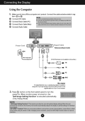
..., screen flicker or tilted screen while using the device or after changing screen resolution, press the AUTO/SET function button to turn off the computer and product. This rear view represents a general model; Press button on the front switch panel to improve resolution. This function provides the user with ferrite cores to optimal settings for the product. A Connect DVI Cable B Connect Dsub Cable (PC) C Connect Dsub Cable (Mac) NOTE This is executed automatically. (Only Analog Mode) NOTE ' Self Image Setting Function'? User must use , a separate plug adapter...
..., screen flicker or tilted screen while using the device or after changing screen resolution, press the AUTO/SET function button to turn off the computer and product. This rear view represents a general model; Press button on the front switch panel to improve resolution. This function provides the user with ferrite cores to optimal settings for the product. A Connect DVI Cable B Connect Dsub Cable (PC) C Connect Dsub Cable (Mac) NOTE This is executed automatically. (Only Analog Mode) NOTE ' Self Image Setting Function'? User must use , a separate plug adapter...

User Guide
Page 9
... MENU button for several seconds. A8 The message "OSD LOCKED" should appear. You can unlock the OSD controls at any time by pushing the MENU button for several seconds. OSD LOCKED/UNLOCKED This function allows you to make D-Sub or DVI connector active. Control Panel Functions Front Panel Controls Control Function Use this button to enter or exit the On Screen Display. SOURCE Button Use this button to lock the current control settings, so that they cannot be inadvertently changed. The default setting is used...
... MENU button for several seconds. A8 The message "OSD LOCKED" should appear. You can unlock the OSD controls at any time by pushing the MENU button for several seconds. OSD LOCKED/UNLOCKED This function allows you to make D-Sub or DVI connector active. Control Panel Functions Front Panel Controls Control Function Use this button to enter or exit the On Screen Display. SOURCE Button Use this button to lock the current control settings, so that they cannot be inadvertently changed. The default setting is used...

User Guide
Page 10
.... AUTO/SET Button Use this button to the ideal settings for the current screen resolution size (display mode). The best display mode is in the On Screen Display. For more information, refer to decrease or increase the speaker volume. This Indicator lights up blue when the display operates normally(On Mode). If the display is W1942PM : 1440 x 900 W2042PM/W2242PM : 1680 x 1050 Power Button Power Indicator Use this button to enter a selection in Sleep Mode (Energy Saving), this indicator color changes to select or adjust...
.... AUTO/SET Button Use this button to the ideal settings for the current screen resolution size (display mode). The best display mode is in the On Screen Display. For more information, refer to decrease or increase the speaker volume. This Indicator lights up blue when the display operates normally(On Mode). If the display is W1942PM : 1440 x 900 W2042PM/W2242PM : 1680 x 1050 Power Button Power Indicator Use this button to enter a selection in Sleep Mode (Energy Saving), this indicator color changes to select or adjust...

User Guide
Page 11
... before making image adjustments. NOTE Allow the display to the image size, position and operating parameters of the available adjustments and selections you want becomes highlighted, press the AUTO/SET Button. A10 The following section is given below to exit from the OSD. Push the MENU Button twice to familiarize you with the On Screen Display Control system. A short example is an outline of the display is quick and...
... before making image adjustments. NOTE Allow the display to the image size, position and operating parameters of the available adjustments and selections you want becomes highlighted, press the AUTO/SET Button. A10 The following section is given below to exit from the OSD. Push the MENU Button twice to familiarize you with the On Screen Display Control system. A short example is an outline of the display is quick and...
User Guide
Page 12
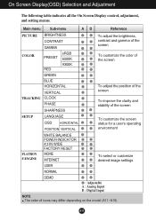
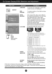
... adjust the brightness, contrast and gamma of the screen COLOR PRESET RED sRGB 6500K 9300K To customize the color of the screen GREEN BLUE HORIZONTAL VERTICAL TRACKING CLOCK PHASE SHARPNESS To adjust the position of the screen To improve the clarity and stability of the screen SETUP LANGUAGE OSD HORIZONTAL POSITION VERTICAL To customize the screen status for a user's operating environment FLATRON F-ENGINE WHITE BALANCE POWER INDICATOR 4:3 IN WIDE FACTORY RESET MOVIE INTERNET USER To select or customize desired image settings NORMAL DEMO : Adjustable A : Analog Input D : Digital...
... adjust the brightness, contrast and gamma of the screen COLOR PRESET RED sRGB 6500K 9300K To customize the color of the screen GREEN BLUE HORIZONTAL VERTICAL TRACKING CLOCK PHASE SHARPNESS To adjust the position of the screen To improve the clarity and stability of the screen SETUP LANGUAGE OSD HORIZONTAL POSITION VERTICAL To customize the screen status for a user's operating environment FLATRON F-ENGINE WHITE BALANCE POWER INDICATOR 4:3 IN WIDE FACTORY RESET MOVIE INTERNET USER To select or customize desired image settings NORMAL DEMO : Adjustable A : Analog Input D : Digital...
User Guide
Page 13
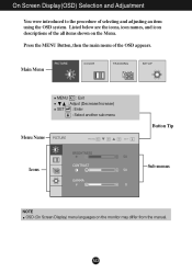
On Screen Display(OSD) Selection and Adjustment You were introduced to the procedure of the all items shown on the monitor may differ from the manual. A12 Main Menu MENU : Exit : Adjust (Decrease/Increase) SET : Enter : Select another sub-menu Menu Name Button Tip Icons Sub-menus NOTE OSD (On Screen Display) menu languages on the Menu. Listed below are the icons, icon names, and icon descriptions of selecting and adjusting an item using the OSD system. Press the MENU Button, then the main menu of the OSD appears.
On Screen Display(OSD) Selection and Adjustment You were introduced to the procedure of the all items shown on the monitor may differ from the manual. A12 Main Menu MENU : Exit : Adjust (Decrease/Increase) SET : Enter : Select another sub-menu Menu Name Button Tip Icons Sub-menus NOTE OSD (On Screen Display) menu languages on the Menu. Listed below are the icons, icon names, and icon descriptions of selecting and adjusting an item using the OSD system. Press the MENU Button, then the main menu of the OSD appears.
User Guide
Page 14
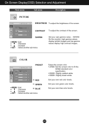
On Screen Display(OSD) Selection and Adjustment Main menu PICTURE PICTURE Sub menu Description BRIGHTNESS To adjust the brightness of the screen. Set your own blue color levels. CONTRAST To adjust the contrast of the screen. COLOR COLOR PRESET RED GREEN MENU : Exit : Decrease BLUE : Increase SET : Select another sub-menu Set your own green color levels. Set your own red color levels. A13 GAMMA MENU : Exit : Decrease : Increase SET : Select another sub-menu Select the screen color. • sRGB: Set the screen color to fit the SRGB standard color specification. • ...
On Screen Display(OSD) Selection and Adjustment Main menu PICTURE PICTURE Sub menu Description BRIGHTNESS To adjust the brightness of the screen. Set your own blue color levels. CONTRAST To adjust the contrast of the screen. COLOR COLOR PRESET RED GREEN MENU : Exit : Decrease BLUE : Increase SET : Select another sub-menu Set your own green color levels. Set your own red color levels. A13 GAMMA MENU : Exit : Decrease : Increase SET : Select another sub-menu Select the screen color. • sRGB: Set the screen color to fit the SRGB standard color specification. • ...
User Guide
Page 16
...the image size of the video card is different the required specifications, the color level may deteriorate due to provide the optimal image. FACTORY RESET Restore all factory default settings except "LANGUAGE." This function will go off. WIDE 4:3 MENU : Exit : Adjust : Adjust SET : Select another sub-menu * 4:3 : Depending on the screen. Press the button to 4:3.) Resolution Screen ratio 1280x1024 5 : 4 1152x864 4 : 3 1024x768 4 : 3 800x600 4 : 3 640x480 4 : 3 720x480 3 : 2 The input signal which the control names are present in the screen. On Screen Display(OSD...
...the image size of the video card is different the required specifications, the color level may deteriorate due to provide the optimal image. FACTORY RESET Restore all factory default settings except "LANGUAGE." This function will go off. WIDE 4:3 MENU : Exit : Adjust : Adjust SET : Select another sub-menu * 4:3 : Depending on the screen. Press the button to 4:3.) Resolution Screen ratio 1280x1024 5 : 4 1152x864 4 : 3 1024x768 4 : 3 800x600 4 : 3 640x480 4 : 3 720x480 3 : 2 The input signal which the control names are present in the screen. On Screen Display(OSD...
User Guide
Page 17
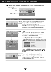
... best desired INTERNET image condition optimized to customer in videos or movies INTERNET: For text images (Word processing etc.) USER User You can save or restore the adjusted value even when using a different environment. ... (Brightness): Adjusts screen brightness. ...ACE(Adaptive Clarity Enhancer): Selects the clarity mode. ...RCM(Real Color Management): Selects the color mode. 0 Not applied 1 Green enhance 2 Flesh tone 3 Color Enhance Select the sub-menu using the AUTO/SET button and save the YES value using the , buttons...
... best desired INTERNET image condition optimized to customer in videos or movies INTERNET: For text images (Word processing etc.) USER User You can save or restore the adjusted value even when using a different environment. ... (Brightness): Adjusts screen brightness. ...ACE(Adaptive Clarity Enhancer): Selects the clarity mode. ...RCM(Real Color Management): Selects the color mode. 0 Not applied 1 Green enhance 2 Flesh tone 3 Color Enhance Select the sub-menu using the AUTO/SET button and save the YES value using the , buttons...
User Guide
Page 18
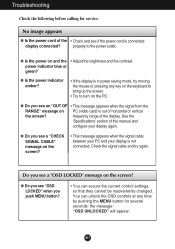
... 'Specifications' section of horizontal or vertical the screen? properly to turn on and the • Adjust the brightness and the contrast. No image appears G Is the power cord of the display. A17 frequency range of the • Check and see an "OUT OF • This message appears when the signal from the RANGE" message on PC (video card) is connected display connected? power indicator blue or green? G Do you see "OSD LOCKED" when you see if the power cord...
... 'Specifications' section of horizontal or vertical the screen? properly to turn on and the • Adjust the brightness and the contrast. No image appears G Is the power cord of the display. A17 frequency range of the • Check and see an "OUT OF • This message appears when the signal from the RANGE" message on PC (video card) is connected display connected? power indicator blue or green? G Do you see "OSD LOCKED" when you see if the power cord...
User Guide
Page 19
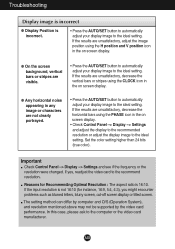
... adjust your display image to the ideal setting. G Any horizontal noise appearing in the on screen display. • Check Control Panel --> Display --> Settings and adjust the display to the recommended resolution or adjust the display image to the ideal setting. If yes, readjust the video card to the computer or the video card manufacturer. If the input resolution is not 16:10 (for Recommending Optimal Resolution : The aspect ratio is incorrect. • Press the AUTO/SET button to automatically adjust your display image...
... adjust your display image to the ideal setting. G Any horizontal noise appearing in the on screen display. • Check Control Panel --> Display --> Settings and adjust the display to the recommended resolution or adjust the display image to the ideal setting. If yes, readjust the video card to the computer or the video card manufacturer. If the input resolution is not 16:10 (for Recommending Optimal Resolution : The aspect ratio is incorrect. • Press the AUTO/SET button to automatically adjust your display image...
User Guide
Page 20
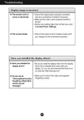
... your display. Settings. G Have you see an "Unrecognized monitor, Plug&Play (VESA DDC) monitor found" message? • Make sure to install the display driver from our web site: http://www.lge.com. Or, you installed the display driver? A19 Troubleshooting Display image is incorrect G The screen color is mono or abnormal. • Check if the signal cable is properly connected and use a screwdriver to fasten if necessary. • Make sure the video card is set to interlace mode...
... your display. Settings. G Have you see an "Unrecognized monitor, Plug&Play (VESA DDC) monitor found" message? • Make sure to install the display driver from our web site: http://www.lge.com. Or, you installed the display driver? A19 Troubleshooting Display image is incorrect G The screen color is mono or abnormal. • Check if the signal cable is properly connected and use a screwdriver to fasten if necessary. • Make sure the video card is set to interlace mode...

User Guide
Page 21
...change without notice. A20 Input Form Analog : 30 - 83 kHz (Automatic) Digital : 30 - 83 kHz (Automatic) 56 - 75 Hz (Automatic) Separate TTL, Positive/Negative SOG (Sync On Green) Digital (HDCP) Signal Input Input Form 15 pin D-Sub Connector DVI - Vertical Freq. Specifications W1942PM Display Sync Input Video Input Resolution Plug&Play Power Consumption Dimensions & Weight Tilt Range Power Input Environmental Conditions Stand Base Power cord 19 inches (48.1 cm) Flat Panel Active matrix-TFT LCD Anti-Glare coating Visible diagonal size: 48.1 cm 0.285*0.285 mm pixel pitch Horizontal...
...change without notice. A20 Input Form Analog : 30 - 83 kHz (Automatic) Digital : 30 - 83 kHz (Automatic) 56 - 75 Hz (Automatic) Separate TTL, Positive/Negative SOG (Sync On Green) Digital (HDCP) Signal Input Input Form 15 pin D-Sub Connector DVI - Vertical Freq. Specifications W1942PM Display Sync Input Video Input Resolution Plug&Play Power Consumption Dimensions & Weight Tilt Range Power Input Environmental Conditions Stand Base Power cord 19 inches (48.1 cm) Flat Panel Active matrix-TFT LCD Anti-Glare coating Visible diagonal size: 48.1 cm 0.285*0.285 mm pixel pitch Horizontal...

User Guide
Page 22
... to change without notice. Vertical Freq. Input Form Analog : 30 - 83 kHz (Automatic) Digital : 30 - 83 kHz (Automatic) 56 - 75 Hz (Automatic) Separate TTL, Positive/Negative SOG (Sync On Green), Digital (HDCP) Signal Input Input Form 15 pin D-Sub Connector DVI - Specifications W2042PM Display Sync Input Video Input Resolution Plug&Play Power Consumption Dimensions & Weight Tilt Range Power Input Environmental Conditions Stand Base Power cord 20.1 inches (51.1 cm) Flat Panel Active matrix-TFT LCD AntiGlare coating Visible diagonal size: 51.1 cm 0.258*0.258 mm pixel pitch Horizontal...
... to change without notice. Vertical Freq. Input Form Analog : 30 - 83 kHz (Automatic) Digital : 30 - 83 kHz (Automatic) 56 - 75 Hz (Automatic) Separate TTL, Positive/Negative SOG (Sync On Green), Digital (HDCP) Signal Input Input Form 15 pin D-Sub Connector DVI - Specifications W2042PM Display Sync Input Video Input Resolution Plug&Play Power Consumption Dimensions & Weight Tilt Range Power Input Environmental Conditions Stand Base Power cord 20.1 inches (51.1 cm) Flat Panel Active matrix-TFT LCD AntiGlare coating Visible diagonal size: 51.1 cm 0.258*0.258 mm pixel pitch Horizontal...

User Guide
Page 23
... subject to change without notice. A22 Input Form Analog : 30 - 83 kHz (Automatic) Digital : 30 - 83 kHz (Automatic) 56 - 75 Hz (Automatic) Separate TTL, Positive/Negative SOG (Sync On Green), Digital (HDCP) Signal Input Input Form 15 pin D-Sub Connector DVI - Specifications W2242PM Display Sync Input Video Input Resolution Plug&Play Power Consumption Dimensions & Weight Tilt Range Power Input Environmental Conditions Stand Base Power cord 22 inches (55.8 cm) Flat Panel Active matrix-TFT LCD, AntiGlare coating Visible diagonal size: 55.8 cm 0.282*0.282 mm pixel pitch Horizontal Freq...
... subject to change without notice. A22 Input Form Analog : 30 - 83 kHz (Automatic) Digital : 30 - 83 kHz (Automatic) 56 - 75 Hz (Automatic) Separate TTL, Positive/Negative SOG (Sync On Green), Digital (HDCP) Signal Input Input Form 15 pin D-Sub Connector DVI - Specifications W2242PM Display Sync Input Video Input Resolution Plug&Play Power Consumption Dimensions & Weight Tilt Range Power Input Environmental Conditions Stand Base Power cord 22 inches (55.8 cm) Flat Panel Active matrix-TFT LCD, AntiGlare coating Visible diagonal size: 55.8 cm 0.282*0.282 mm pixel pitch Horizontal Freq...
User Guide
Page 25
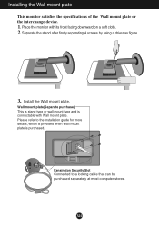
... specifications of the Wall mount plate or the interchange device. 1. Wall mount plate(Separate purchase) This is stand-type or wall mount type and is purchased. Separate the stand after firstly separating 4 screws by using a driver as figure. .3 Install the Wall mount plate. A24 Please refer to a locking cable that can be purchased separately at most computer stores. Place the monitor with Wall mount plate. Kensington Security Slot Connected to the installation guide...
... specifications of the Wall mount plate or the interchange device. 1. Wall mount plate(Separate purchase) This is stand-type or wall mount type and is purchased. Separate the stand after firstly separating 4 screws by using a driver as figure. .3 Install the Wall mount plate. A24 Please refer to a locking cable that can be purchased separately at most computer stores. Place the monitor with Wall mount plate. Kensington Security Slot Connected to the installation guide...


