Owner's Manual (English)
Page 2
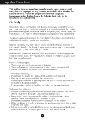
... power supply cord is easily accessible after installation. Ensure that the socket-outlet is used as the main disconnection device. Operate the display only from a power source indicated in the specifications of all safeguards incorporated in this display, observe the following basic rules for an extended period of thunder and lightning, never touch the power cord and signal cable because it is OFF. Call your service...
... power supply cord is easily accessible after installation. Ensure that the socket-outlet is used as the main disconnection device. Operate the display only from a power source indicated in the specifications of all safeguards incorporated in this display, observe the following basic rules for an extended period of thunder and lightning, never touch the power cord and signal cable because it is OFF. Call your service...
Owner's Manual (English)
Page 3
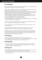
... obtain the best image quality for a long time as this may scratch, mar, or damage the Active Matrix LCD permanently. Displays are blocked, built-up heat can cause failures which to another location, repack it is easy to damage. Do not use this display near water such as Red, Green or Blue spots on the display screen because over the power cord, and...
... obtain the best image quality for a long time as this may scratch, mar, or damage the Active Matrix LCD permanently. Displays are blocked, built-up heat can cause failures which to another location, repack it is easy to damage. Do not use this display near water such as Red, Green or Blue spots on the display screen because over the power cord, and...
Owner's Manual (English)
Page 4
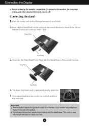
.... 2. Stand Base Stand Body 4. Once assembled take the monitor up the monitor, ensure that the power to perpendicularity direction. 5. Assemble the Stand Body into the Stand Body in the correct direction. Hinge Body Stand Body 3. Connecting the Display Before setting up carefully and face the front side Important This illustration depicts the general model of connection. Do not carry the product upside down the base lock to the monitor...
.... 2. Stand Base Stand Body 4. Once assembled take the monitor up the monitor, ensure that the power to perpendicularity direction. 5. Assemble the Stand Body into the Stand Body in the correct direction. Hinge Body Stand Body 3. Connecting the Display Before setting up carefully and face the front side Important This illustration depicts the general model of connection. Do not carry the product upside down the base lock to the monitor...
Owner's Manual (English)
Page 5
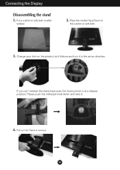
Change your lock on the product as it follows and turn it . 4. Put a cushion or soft cloth on the cushion or soft cloth. 3. Place the monitor face Down on aflat surface. 2. If you can't release the stand base even the locking knob is at a release position, Please push the indicated knob down and retry it in the arrow direction. A4 Connecting the Display Disassembling the stand 1. Pull out the Stand to remove.
Change your lock on the product as it follows and turn it . 4. Put a cushion or soft cloth on the cushion or soft cloth. 3. Place the monitor face Down on aflat surface. 2. If you can't release the stand base even the locking knob is at a release position, Please push the indicated knob down and retry it in the arrow direction. A4 Connecting the Display Disassembling the stand 1. Pull out the Stand to remove.
Owner's Manual (English)
Page 6
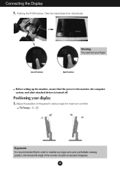
... devices is recommended that the power to maintain an ergonomic and comfortable viewing position, the forward tilt angle of the panel in various ways for maximum comfort. Tilt Range : -5˚~20˚ 20 Ergonomic It is turned off. Pushing the PUSH button, Take the stand base from stand body. Positioning your finger. Adjust the position of the monitor should not exceed 5 degrees. A5 Connecting the Display 5. Warning: You can hurt...
... devices is recommended that the power to maintain an ergonomic and comfortable viewing position, the forward tilt angle of the panel in various ways for maximum comfort. Tilt Range : -5˚~20˚ 20 Ergonomic It is turned off. Pushing the PUSH button, Take the stand base from stand body. Positioning your finger. Adjust the position of the monitor should not exceed 5 degrees. A5 Connecting the Display 5. Warning: You can hurt...
Owner's Manual (English)
Page 7
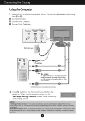
... after changing screen resolution, press the AUTO/SET function button to a 15 pin 2 row connector. When monitor power is turned on, the 'Self Image Setting Function' is needed to 2 . When you encounter problems such as below sketch map form 1 to change the 15 pin high density (3 row) Dsub VGA connector on . A Connect DVI Cable B Connect Dsub Cable (PC) C Connect Dsub Cable (Mac) Power Cord Analog signal Digital signal D-sub DVI PUSH Wall-outlet type PC PC-outlet type PC B MAC c Mac adapter For Apple Macintosh use, a separate plug adapter...
... after changing screen resolution, press the AUTO/SET function button to a 15 pin 2 row connector. When monitor power is turned on, the 'Self Image Setting Function' is needed to 2 . When you encounter problems such as below sketch map form 1 to change the 15 pin high density (3 row) Dsub VGA connector on . A Connect DVI Cable B Connect Dsub Cable (PC) C Connect Dsub Cable (Mac) Power Cord Analog signal Digital signal D-sub DVI PUSH Wall-outlet type PC PC-outlet type PC B MAC c Mac adapter For Apple Macintosh use, a separate plug adapter...
Owner's Manual (English)
Page 9
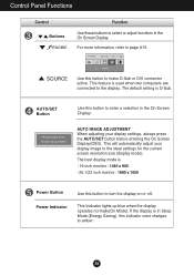
... - 20.1/22 inch monitor : 1680 x 1050 Power Button Power Indicator Use this button to page A15. AUTO IMAGE ADJUSTMENT When adjusting your display image to the ideal settings for the current screen resolution size (display mode). A8 Control Panel Functions Control Buttons Function Use these buttons to select or adjust functions in the On Screen Display. The best display mode is used when two computers are connected to the display. Use this button to turn the display on or off. If the display is D-Sub. This will automatically adjust your display settings, always...
... - 20.1/22 inch monitor : 1680 x 1050 Power Button Power Indicator Use this button to page A15. AUTO IMAGE ADJUSTMENT When adjusting your display image to the ideal settings for the current screen resolution size (display mode). A8 Control Panel Functions Control Buttons Function Use these buttons to select or adjust functions in the On Screen Display. The best display mode is used when two computers are connected to the display. Use this button to turn the display on or off. If the display is D-Sub. This will automatically adjust your display settings, always...
Owner's Manual (English)
Page 11
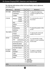
...-menu A D Reference PICTURE BRIGHTNESS CONTRAST GAMMA To adjust the brightness, contrast and gamma of the screen COLOR PRESET RED sRGB 6500K 9300K To customize the color of the screen GREEN BLUE HORIZONTAL VERTICAL TRACKING CLOCK PHASE SHARPNESS To adjust the position of the screen To improve the clarity and stability of the screen SETUP LANGUAGE OSD HORIZONTAL POSITION VERTICAL To customize the screen status for a user's operating environment WHITE BALANCE POWER INDICATOR FACTORY RESET FLATRON F-ENGINE MOVIE INTERNET USER To select or customize desired image settings...
...-menu A D Reference PICTURE BRIGHTNESS CONTRAST GAMMA To adjust the brightness, contrast and gamma of the screen COLOR PRESET RED sRGB 6500K 9300K To customize the color of the screen GREEN BLUE HORIZONTAL VERTICAL TRACKING CLOCK PHASE SHARPNESS To adjust the position of the screen To improve the clarity and stability of the screen SETUP LANGUAGE OSD HORIZONTAL POSITION VERTICAL To customize the screen status for a user's operating environment WHITE BALANCE POWER INDICATOR FACTORY RESET FLATRON F-ENGINE MOVIE INTERNET USER To select or customize desired image settings...
Owner's Manual (English)
Page 12
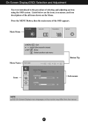
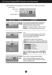
Listed below are the icons, icon names, and icon descriptions of selecting and adjusting an item using the OSD system. Main Menu MENU : Exit - + : Adjust (Decrease/Increase) SET : Enter : Select another sub-menu Menu Name Button Tip Icons Sub-menus NOTE OSD (On Screen Display) menu languages on the Menu. On Screen Display(OSD) Selection and Adjustment You were introduced to the procedure of the all items shown on the monitor may differ from the manual. A11 Press the MENU Button, then the main menu of the OSD appears.
Listed below are the icons, icon names, and icon descriptions of selecting and adjusting an item using the OSD system. Main Menu MENU : Exit - + : Adjust (Decrease/Increase) SET : Enter : Select another sub-menu Menu Name Button Tip Icons Sub-menus NOTE OSD (On Screen Display) menu languages on the Menu. On Screen Display(OSD) Selection and Adjustment You were introduced to the procedure of the all items shown on the monitor may differ from the manual. A11 Press the MENU Button, then the main menu of the OSD appears.
Owner's Manual (English)
Page 13
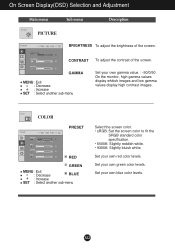
... On the monitor, high gamma values display whitish images and low gamma values display high contrast images. On Screen Display(OSD) Selection and Adjustment Main menu PICTURE PICTURE Sub menu Description BRIGHTNESS To adjust the brightness of the screen. A12 COLOR COLOR PRESET RED GREEN MENU : Exit : Decrease BLUE : Increase SET : Select another sub-menu Set your own red color levels. GAMMA MENU : Exit : Decrease : Increase SET : Select another sub-menu Select the screen color. • sRGB: Set the screen color to fit the SRGB standard color specification. •...
... On the monitor, high gamma values display whitish images and low gamma values display high contrast images. On Screen Display(OSD) Selection and Adjustment Main menu PICTURE PICTURE Sub menu Description BRIGHTNESS To adjust the brightness of the screen. A12 COLOR COLOR PRESET RED GREEN MENU : Exit : Decrease BLUE : Increase SET : Select another sub-menu Set your own red color levels. GAMMA MENU : Exit : Decrease : Increase SET : Select another sub-menu Select the screen color. • sRGB: Set the screen color to fit the SRGB standard color specification. •...
Owner's Manual (English)
Page 15
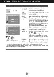
...optimal image. Restore all factory default settings except - On Screen Display(OSD) Selection and Adjustment Main menu Sub menu Description LANGUAGE To choose the language in which the SETUP SETUP control names are present in order to set the power indicator on the screen. If this function, the signal level is an analog signal. MENU : Exit : Adjust : Adjust SET : Select another sub-menu POWER INDICATOR FACTORY RESET Use this function when white and black colors are displayed. Using this does not improve the screen image, restore the factory default settings...
...optimal image. Restore all factory default settings except - On Screen Display(OSD) Selection and Adjustment Main menu Sub menu Description LANGUAGE To choose the language in which the SETUP SETUP control names are present in order to set the power indicator on the screen. If this function, the signal level is an analog signal. MENU : Exit : Adjust : Adjust SET : Select another sub-menu POWER INDICATOR FACTORY RESET Use this function when white and black colors are displayed. Using this does not improve the screen image, restore the factory default settings...
Owner's Manual (English)
Page 16
... image condition optimized to customer in videos or movies INTERNET: For text images (Word processing etc.) USER User You can save or restore the adjusted value even when using a different environment. ... (Brightness): Adjusts screen brightness. ...ACE(Adaptive Clarity Enhancer): Selects the clarity mode. ...RCM(Real Color Management): Selects the color mode. 0 Not applied 1 Green enhance 2 Flesh tone 3 Color Enhance Select the sub-menu using the AUTO/SET button and save the YES value using the , buttons. You can manually adjust brightness...
... image condition optimized to customer in videos or movies INTERNET: For text images (Word processing etc.) USER User You can save or restore the adjusted value even when using a different environment. ... (Brightness): Adjusts screen brightness. ...ACE(Adaptive Clarity Enhancer): Selects the clarity mode. ...RCM(Real Color Management): Selects the color mode. 0 Not applied 1 Green enhance 2 Flesh tone 3 Color Enhance Select the sub-menu using the AUTO/SET button and save the YES value using the , buttons. You can manually adjust brightness...
Owner's Manual (English)
Page 17
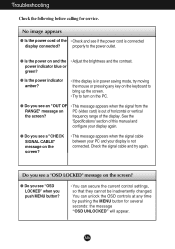
... the screen. • Try to the power outlet. ● Is the power on the PC. ● Do you see "OSD LOCKED" when you see if the power cord is not connected. properly to turn on and the • Adjust the brightness and the contrast. power indicator blue or green? ● Is the power indicator amber? • If the display is out of the display. frequency range of horizontal or vertical the screen? A16...
... the screen. • Try to the power outlet. ● Is the power on the PC. ● Do you see "OSD LOCKED" when you see if the power cord is not connected. properly to turn on and the • Adjust the brightness and the contrast. power indicator blue or green? ● Is the power indicator amber? • If the display is out of the display. frequency range of horizontal or vertical the screen? A16...
Owner's Manual (English)
Page 18
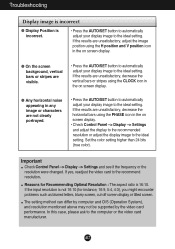
... the vertical bars or stripes using the PHASE icon in the on screen display. ● On the screen background, vertical bars or stripes are visible. • Press the AUTO/SET button to automatically adjust your display image to the ideal setting. A17 Important Check Control Panel --> Display --> Settings and see if the frequency or the resolution were changed. If yes, readjust the video card to the computer or the video card manufacturer. Set the color setting higher than...
... the vertical bars or stripes using the PHASE icon in the on screen display. ● On the screen background, vertical bars or stripes are visible. • Press the AUTO/SET button to automatically adjust your display image to the ideal setting. A17 Important Check Control Panel --> Display --> Settings and see if the frequency or the resolution were changed. If yes, readjust the video card to the computer or the video card manufacturer. Set the color setting higher than...
Owner's Manual (English)
Page 19
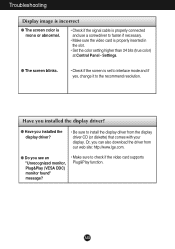
...; Do you installed the display driver? • Be sure to check if the video card supports Plug&Play function. Settings. ● The screen blinks. • Check if the screen is set to interlace mode and if yes, change it to fasten if necessary. • Make sure the video card is properly connected and use a screwdriver to the recommend resolution. Troubleshooting Display image is incorrect ● The screen color is mono or abnormal. • Check if the signal cable is properly...
...; Do you installed the display driver? • Be sure to check if the video card supports Plug&Play function. Settings. ● The screen blinks. • Check if the screen is set to interlace mode and if yes, change it to fasten if necessary. • Make sure the video card is properly connected and use a screwdriver to the recommend resolution. Troubleshooting Display image is incorrect ● The screen color is mono or abnormal. • Check if the signal cable is properly...
Owner's Manual (English)
Page 20
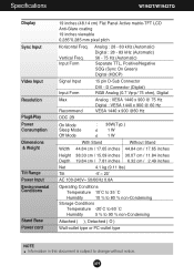
... ˚C Humidity 5 % to 90 % non-Condensing Attached ( ), Detached ( O ) Wall-outlet type or PC-outlet type NOTE Information in this document is subject to change without notice. A19 Vertical Freq. Specifications W1942T/W1942TQ Display Sync Input Video Input Resolution Plug&Play Power Consumption Dimensions & Weight Tilt Range Power Input Environmental Conditions Stand Base Power cord 19 inches (48.14 cm) Flat Panel Active matrix-TFT LCD Anti-Glare coating 19 inches viewable 0.285*0.285 mm pixel pitch Horizontal Freq.
... ˚C Humidity 5 % to 90 % non-Condensing Attached ( ), Detached ( O ) Wall-outlet type or PC-outlet type NOTE Information in this document is subject to change without notice. A19 Vertical Freq. Specifications W1942T/W1942TQ Display Sync Input Video Input Resolution Plug&Play Power Consumption Dimensions & Weight Tilt Range Power Input Environmental Conditions Stand Base Power cord 19 inches (48.14 cm) Flat Panel Active matrix-TFT LCD Anti-Glare coating 19 inches viewable 0.285*0.285 mm pixel pitch Horizontal Freq.

Owner's Manual (English)
Page 21
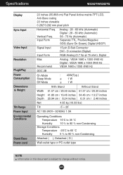
... to change without notice. Input Form Analog : 28 - 83 kHz (Automatic) Digital : 28 - 83 kHz (Automatic) 56 - 75 Hz (Automatic) Separate TTL, Positive/Negative SOG (Sync On Green), Digital (HDCP) Signal Input Input Form 15 pin D-Sub Connector DVI - Specifications W2042T/W2042TQ Display Sync Input Video Input Resolution Plug&Play Power Consumption Dimensions & Weight Tilt Range Power Input Environmental Conditions Stand Base Power cord 20.1 inches (51.11 cm) Flat Panel Active matrix-TFT LCD Anti-Glare coating 20.1 inches viewable 0.258*0.258 mm pixel pitch Horizontal Freq. Vertical...
... to change without notice. Input Form Analog : 28 - 83 kHz (Automatic) Digital : 28 - 83 kHz (Automatic) 56 - 75 Hz (Automatic) Separate TTL, Positive/Negative SOG (Sync On Green), Digital (HDCP) Signal Input Input Form 15 pin D-Sub Connector DVI - Specifications W2042T/W2042TQ Display Sync Input Video Input Resolution Plug&Play Power Consumption Dimensions & Weight Tilt Range Power Input Environmental Conditions Stand Base Power cord 20.1 inches (51.11 cm) Flat Panel Active matrix-TFT LCD Anti-Glare coating 20.1 inches viewable 0.258*0.258 mm pixel pitch Horizontal Freq. Vertical...
Owner's Manual (English)
Page 22
... notice. A21 Specifications W2242T/W2242TQ Display Sync Input Video Input Resolution Plug&Play Power Consumption Dimensions & Weight Tilt Range Power Input Environmental Conditions Stand Base Power cord 22 inches (55.868 cm) Flat Panel Active matrix-TFT LCD, Anti-Glare coating 22 inches viewable 0.282*0.282 mm pixel pitch Horizontal Freq. Vertical Freq. Input Form Analog : 28 - 83 kHz (Automatic) Digital : 28 - 83 kHz (Automatic) 56 - 75 Hz (Automatic) Separate TTL, Positive/Negative SOG (Sync On Green), Digital (HDCP) Signal Input Input Form 15 pin D-Sub Connector DVI -
... notice. A21 Specifications W2242T/W2242TQ Display Sync Input Video Input Resolution Plug&Play Power Consumption Dimensions & Weight Tilt Range Power Input Environmental Conditions Stand Base Power cord 22 inches (55.868 cm) Flat Panel Active matrix-TFT LCD, Anti-Glare coating 22 inches viewable 0.282*0.282 mm pixel pitch Horizontal Freq. Vertical Freq. Input Form Analog : 28 - 83 kHz (Automatic) Digital : 28 - 83 kHz (Automatic) 56 - 75 Hz (Automatic) Separate TTL, Positive/Negative SOG (Sync On Green), Digital (HDCP) Signal Input Input Form 15 pin D-Sub Connector DVI -
Owner's Manual (English)
Page 23
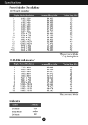
... 75 *Recommend Mode **Only Analog Mode Horizontal Freq. (kHz) 31.468 31.469 37.500 37.879 46.875 48.363 60.123 67.500 63.981 79.976 64.674 65.290 Vertical Freq. (Hz) 70 60 75 60 75 60 75 75 60 75 60 60 *Recommend Mode Indicator MODE On Mode Sleep Mode Off Mode LED Color blue amber Off A22
... 75 *Recommend Mode **Only Analog Mode Horizontal Freq. (kHz) 31.468 31.469 37.500 37.879 46.875 48.363 60.123 67.500 63.981 79.976 64.674 65.290 Vertical Freq. (Hz) 70 60 75 60 75 60 75 75 60 75 60 60 *Recommend Mode Indicator MODE On Mode Sleep Mode Off Mode LED Color blue amber Off A22
Owner's Manual (English)
Page 24
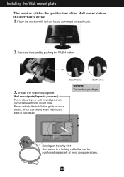
... the PUSH button. .3 Install the Wall mount plate. Good Position Bad Position Warning: You can be purchased separately at most computer stores. Installing the Wall mount plate This monitor satisfies the specifications of the Wall mount plate or the interchange device. 1. A23 Wall mount plate(Separate purchase) This is stand-type or wall mount type and is purchased. Place the monitor with Wall mount plate. Kensington Security Slot Connected to the installation guide for...
... the PUSH button. .3 Install the Wall mount plate. Good Position Bad Position Warning: You can be purchased separately at most computer stores. Installing the Wall mount plate This monitor satisfies the specifications of the Wall mount plate or the interchange device. 1. A23 Wall mount plate(Separate purchase) This is stand-type or wall mount type and is purchased. Place the monitor with Wall mount plate. Kensington Security Slot Connected to the installation guide for...


