Owner's Manual (English)
Page 4
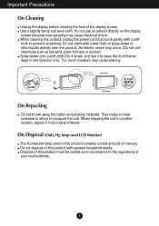
... directly on the display screen because over-spraying may cause staining. When shipping the unit to transport the unit. On Disposal (Only, Hg lamp used LCD Monitor) The fluorescent lamp used in one direction only. Disposal of mercury. When cleaning the product, unplug the power cord and scrub gently with a soft cloth...
... directly on the display screen because over-spraying may cause staining. When shipping the unit to transport the unit. On Disposal (Only, Hg lamp used LCD Monitor) The fluorescent lamp used in one direction only. Disposal of mercury. When cleaning the product, unplug the power cord and scrub gently with a soft cloth...
Owner's Manual (English)
Page 5
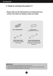
Please make sure the following items are missing, contact your monitor. Accessories !!! If any items are included with ferrite cores to this signal cable may look different from those shown here. User's Guide/Cards Power Cord (...
Please make sure the following items are missing, contact your monitor. Accessories !!! If any items are included with ferrite cores to this signal cable may look different from those shown here. User's Guide/Cards Power Cord (...

Owner's Manual (English)
Page 6
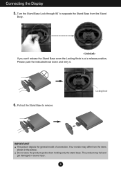
Place the monitor face down on the soft cloth. 2. Once assembled, lift the monitor up the monitor, ensure that the power to the Stand Body. Stand Body Stand Base 3. Turn the Stand Base Lock through 90˚ to fix the Stand Base to the monitor, the computer system, and other attached devices are turned off. Base Lock 4. Connecting and Disassembling the stand 1. Assemble the Stand Base into the Stand Body in the correct direction. Connecting the Display Before setting up carefully. 5
Place the monitor face down on the soft cloth. 2. Once assembled, lift the monitor up the monitor, ensure that the power to the Stand Body. Stand Body Stand Base 3. Turn the Stand Base Lock through 90˚ to fix the Stand Base to the monitor, the computer system, and other attached devices are turned off. Base Lock 4. Connecting and Disassembling the stand 1. Assemble the Stand Base into the Stand Body in the correct direction. Connecting the Display Before setting up carefully. 5
Owner's Manual (English)
Page 7
The product may differ from the Stand Body. Pull out the Stand Base to separate the Stand Base from the items shown in the picture. If you can't release the Stand Base even the Locking Knob is at a release position, Please push the indicated knob down holding only the stand base. Do not carry the product upside down and retry it. 6. Locking Knob IMPORTANT This picture depicts the general model of connection. Turn the Stand Base Lock through 90˚ to remove. Your monitor may fall and get damaged or cause injury. 6 Connecting the Display 5.
The product may differ from the Stand Body. Pull out the Stand Base to separate the Stand Base from the items shown in the picture. If you can't release the Stand Base even the Locking Knob is at a release position, Please push the indicated knob down holding only the stand base. Do not carry the product upside down and retry it. 6. Locking Knob IMPORTANT This picture depicts the general model of connection. Turn the Stand Base Lock through 90˚ to remove. Your monitor may fall and get damaged or cause injury. 6 Connecting the Display 5.
Owner's Manual (English)
Page 8
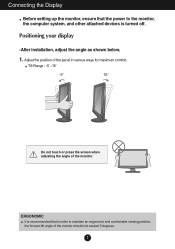
... attached devices is recommended that the power to maintain an ergonomic and comfortable viewing position, the forward tilt angle of the monitor should not exceed 5 degrees. 7 Adjust the position of the monitor. ERGONOMIC It is turned off. Positioning your display -After installation, adjust the angle as shown below. 1. Connecting the Display Before...
... attached devices is recommended that the power to maintain an ergonomic and comfortable viewing position, the forward tilt angle of the monitor should not exceed 5 degrees. 7 Adjust the position of the monitor. ERGONOMIC It is turned off. Positioning your display -After installation, adjust the angle as shown below. 1. Connecting the Display Before...
Owner's Manual (English)
Page 9
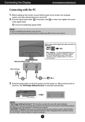
...tilted screen while using a D-Sub signal input cable connector for the first time, this function automatically adjusts the display to the monitor, the computer system, and other attached devices is turned on the front panel to model. This function provides the user with the...resolution, press the AUTO/SET function button to a 15 pin 2 row connector. Connecting the Display W1943TB/W2043TE/W2243T Connecting with optimal display settings.When the user connects the monitor for Macintosh Mac adapter : For older Apple Macintosh use, a separate plug adapter is a simplified ...
...tilted screen while using a D-Sub signal input cable connector for the first time, this function automatically adjusts the display to the monitor, the computer system, and other attached devices is turned on the front panel to model. This function provides the user with the...resolution, press the AUTO/SET function button to a 15 pin 2 row connector. Connecting the Display W1943TB/W2043TE/W2243T Connecting with optimal display settings.When the user connects the monitor for Macintosh Mac adapter : For older Apple Macintosh use, a separate plug adapter is a simplified ...
Owner's Manual (English)
Page 10
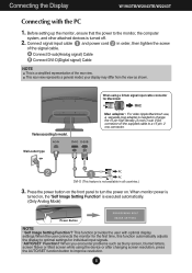
Connecting the Display W1943SB/W2043SE/W2243S Connecting with optimal display settings.When the user connects the monitor for the first time, this function automatically adjusts the display to optimal settings for Macintosh Mac adapter : For older Apple Macintosh use, a separate ...cord 2 in order, then tighten the screw of the rear view. Varies according to the monitor, the computer system, and other attached devices is turned on . Wall-outlet type A PC 3. Before setting up the monitor, ensure that the power to model. your display may differ from the view as blurry ...
Connecting the Display W1943SB/W2043SE/W2243S Connecting with optimal display settings.When the user connects the monitor for the first time, this function automatically adjusts the display to optimal settings for Macintosh Mac adapter : For older Apple Macintosh use, a separate ...cord 2 in order, then tighten the screw of the rear view. Varies according to the monitor, the computer system, and other attached devices is turned on . Wall-outlet type A PC 3. Before setting up the monitor, ensure that the power to model. your display may differ from the view as blurry ...
Owner's Manual (English)
Page 15
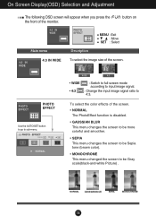
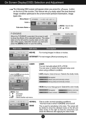
button on Main menu 4:3 IN WIDE MENU : Exit : Move SET : Select Description To select the image size of the monitor. NORMAL GAUSSIAN BLUR SEPIA MONOCHROME 14 To select the color effects of the screen. • NORMAL The PhotoEffect function is disabled. • GAUSSIAN BLUR This ...
button on Main menu 4:3 IN WIDE MENU : Exit : Move SET : Select Description To select the image size of the monitor. NORMAL GAUSSIAN BLUR SEPIA MONOCHROME 14 To select the color effects of the screen. • NORMAL The PhotoEffect function is disabled. • GAUSSIAN BLUR This ...
Owner's Manual (English)
Page 16
... on the left and the inactive state is turned off. The active state is to the left and video mode on the front of the monitor.This feature lets you press the button on the right so that the consumers can check the difference after applying the video mode. 15 USER...
... on the left and the inactive state is turned off. The active state is to the left and video mode on the front of the monitor.This feature lets you press the button on the right so that the consumers can check the difference after applying the video mode. 15 USER...
Owner's Manual (English)
Page 17
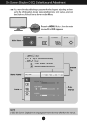
Listed below are the icons, icon names, and icon descriptions of the all items shown on the monitor may differ from the manual. 16 MENU : Exit : Adjust (Decrease/Increase) SET : Enter : Select another sub-menu : Restart to the procedure of the OSD appears. Main Menu Press the MENU Button, then the main menu of selecting and adjusting an item using the OSD system. On Screen Display(OSD) Selection and Adjustment You were introduced to select sub-menu Menu Name Icons Button Tip Submenus NOTE OSD (On Screen Display) menu languages on the Menu.
Listed below are the icons, icon names, and icon descriptions of the all items shown on the monitor may differ from the manual. 16 MENU : Exit : Adjust (Decrease/Increase) SET : Enter : Select another sub-menu : Restart to the procedure of the OSD appears. Main Menu Press the MENU Button, then the main menu of selecting and adjusting an item using the OSD system. On Screen Display(OSD) Selection and Adjustment You were introduced to select sub-menu Menu Name Icons Button Tip Submenus NOTE OSD (On Screen Display) menu languages on the Menu.
Owner's Manual (English)
Page 18
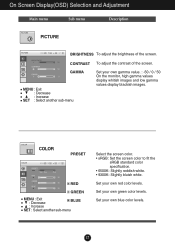
.... • 6500K: Slightly reddish white. • 9300K: Slightly bluish white. Set your own red color levels. Set your own gamma value. : -50 / 0 / 50 On the monitor, high gamma values display whitish images and low gamma values display blackish images. CONTRAST To adjust the contrast of the screen.
.... • 6500K: Slightly reddish white. • 9300K: Slightly bluish white. Set your own red color levels. Set your own gamma value. : -50 / 0 / 50 On the monitor, high gamma values display whitish images and low gamma values display blackish images. CONTRAST To adjust the contrast of the screen.
Owner's Manual (English)
Page 20
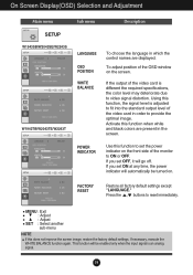
.... FACTORY RESET Restore all factory default settings except "LANGUAGE." On Screen Display(OSD) Selection and Adjustment Main menu SETUP W1943SB/W2043SE/W2243S W1943TB/W2043TE/W2243T Sub menu LANGUAGE OSD POSITION WHITE BALANCE POWER INDICATOR Description To choose the language in which the control names are present in ...If this function to fit into the standard output level of the OSD window on the screen. If the output of the monitor to reset immediately. Use this does not improve the screen image, restore the factory default settings. This function will go off.
.... FACTORY RESET Restore all factory default settings except "LANGUAGE." On Screen Display(OSD) Selection and Adjustment Main menu SETUP W1943SB/W2043SE/W2243S W1943TB/W2043TE/W2243T Sub menu LANGUAGE OSD POSITION WHITE BALANCE POWER INDICATOR Description To choose the language in which the control names are present in ...If this function to fit into the standard output level of the OSD window on the screen. If the output of the monitor to reset immediately. Use this does not improve the screen image, restore the factory default settings. This function will go off.
Owner's Manual (English)
Page 23
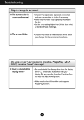
... is properly inserted in the slot. • Set the color setting higher than 24 bits (true color) at Control Panel - Or, you see an "Unrecognized monitor, Plug&Play (VESA DDC) monitor found" message? Settings.
... is properly inserted in the slot. • Set the color setting higher than 24 bits (true color) at Control Panel - Or, you see an "Unrecognized monitor, Plug&Play (VESA DDC) monitor found" message? Settings.
Owner's Manual (English)
Page 32
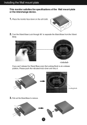
Pull out the Stand Base to separate the Stand Base from the Stand Body. Turn the Stand Base Lock through 90˚ to remove. Locking Knob 31 Place the monitor face down and retry it. 3. Installing the Wall mount plate This monitor satisfies the specifications of the Wall mount plate or the interchange device. 1. If you can't release the Stand Base even the Locking Knob is at a release position, Please push the indicated knob down on the soft cloth. 2.
Pull out the Stand Base to separate the Stand Base from the Stand Body. Turn the Stand Base Lock through 90˚ to remove. Locking Knob 31 Place the monitor face down and retry it. 3. Installing the Wall mount plate This monitor satisfies the specifications of the Wall mount plate or the interchange device. 1. If you can't release the Stand Base even the Locking Knob is at a release position, Please push the indicated knob down on the soft cloth. 2.


