
Service Manual
Page 8
..., PCS : 30dBm(Level 0) Class 10 3V Small Only LCD : TFT 176 × 220 pixel 260K Color Hard icons. PERFORMANCE 2.1 H/W Features Item Standard Battery Stand by Current Talk time Stand by time Charging time RX Sensitivity TX output power GPRS compatibility SIM card type Display Status Indicator ANT EAR... Phone Jack PC Synchronization Speech coding Data and Fax Vibrator Loud Speaker Voice Recoding Microphone Speaker/Receiver Travel Adapter MIDI MP3/AAC Options ...
..., PCS : 30dBm(Level 0) Class 10 3V Small Only LCD : TFT 176 × 220 pixel 260K Color Hard icons. PERFORMANCE 2.1 H/W Features Item Standard Battery Stand by Current Talk time Stand by time Charging time RX Sensitivity TX output power GPRS compatibility SIM card type Display Status Indicator ANT EAR... Phone Jack PC Synchronization Speech coding Data and Fax Vibrator Loud Speaker Voice Recoding Microphone Speaker/Receiver Travel Adapter MIDI MP3/AAC Options ...
Service Manual
Page 12
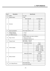
... mA Antenna Bar Number Power 5 -85 dBm ~ 4 -90 dBm ~ -86 dBm 3 -95 dBm ~ -91 dBm 2 -100 dBm ~ -96 dBm 1 -105 dBm ~ -101 dBm 0 ~ -105 dBm Battery Bar Number Voltage 0 3.36 ~ 3.54 V 1 3.55 ~ 3.66 V 2 3.67 ~ 3.72 V 3 3.73 ~ 3.84 V 4 3.85 V ~ 3.55 0.03V (Call) 3.48 0.03V (Standby) - 13 -... Distortion 17 Side Tone Distortion System frequency 18 (13 MHz) tolerance 19 32.768KHz tolerance 20 Ringer Volume 21 Charge Current 22 Antenna Display 23 Battery Indicator 24 Low Voltage Warning Specification 13 5 dB > 6 dB dB to ARL (dB) -35 -30 -20 -10 0 7 10 Three stage distortion...
... mA Antenna Bar Number Power 5 -85 dBm ~ 4 -90 dBm ~ -86 dBm 3 -95 dBm ~ -91 dBm 2 -100 dBm ~ -96 dBm 1 -105 dBm ~ -101 dBm 0 ~ -105 dBm Battery Bar Number Voltage 0 3.36 ~ 3.54 V 1 3.55 ~ 3.66 V 2 3.67 ~ 3.72 V 3 3.73 ~ 3.84 V 4 3.85 V ~ 3.55 0.03V (Call) 3.48 0.03V (Standby) - 13 -... Distortion 17 Side Tone Distortion System frequency 18 (13 MHz) tolerance 19 32.768KHz tolerance 20 Ringer Volume 21 Charge Current 22 Antenna Display 23 Battery Indicator 24 Low Voltage Warning Specification 13 5 dB > 6 dB dB to ARL (dB) -35 -30 -20 -10 0 7 10 Three stage distortion...
Service Manual
Page 13
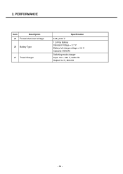
2. PERFORMANCE Item Description 25 Forced shut down Voltage 26 Battery Type 27 Travel Charger Specification 3.35 0.03 V 1 Li-Poly Battery Standard Voltage = 3.7 V Battery full charge voltage = 4.2 V Capacity: 800mAh Switching-mode charger Input: 100 ~ 240 V, 50/60 Hz Output: 5.2 V, 800 mA - 14 -
2. PERFORMANCE Item Description 25 Forced shut down Voltage 26 Battery Type 27 Travel Charger Specification 3.35 0.03 V 1 Li-Poly Battery Standard Voltage = 3.7 V Battery full charge voltage = 4.2 V Capacity: 800mAh Switching-mode charger Input: 100 ~ 240 V, 50/60 Hz Output: 5.2 V, 800 mA - 14 -
Service Manual
Page 20
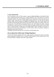
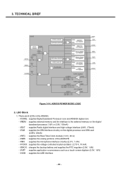
... the BAND_SELECT signal. The RF output ports of the SKY74400 are internally matched to a 50 load to reduce the number of PA circuitry to minimize battery drain. (4) Low Drop-Out (LDO) Linear Voltage Regulators The SKY74400 includes integrated LDO linear voltage regulators to variations in the SKY74400 includes a separate, internal LDO...
... the BAND_SELECT signal. The RF output ports of the SKY74400 are internally matched to a 50 load to reduce the number of PA circuitry to minimize battery drain. (4) Low Drop-Out (LDO) Linear Voltage Regulators The SKY74400 includes integrated LDO linear voltage regulators to variations in the SKY74400 includes a separate, internal LDO...
Service Manual
Page 28
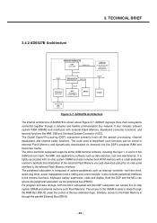
..., test and maintenance. AD6527B Architecture The internal architecture of the external Flash Memory via the peripheral bus (PBUS). The access to the terminal functions: keyboard, battery supervision, radio and display.
..., test and maintenance. AD6527B Architecture The internal architecture of the external Flash Memory via the peripheral bus (PBUS). The access to the terminal functions: keyboard, battery supervision, radio and display.
Service Manual
Page 30
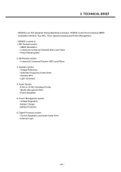
... the processing GMSK modulation interface, Aux ADC, Voice signal processing and Power Management. • AD6535 consists of 1. Power Management section • Voltage Regulators • Battery Charger • Battery Protection 6. Digital Processor section • Control, Baseband, and Audio Serial Ports • Interrupt Logic - 31 - Audio Section • 8 kHz & 16 kHz Voiceband Codec •...
... the processing GMSK modulation interface, Aux ADC, Voice signal processing and Power Management. • AD6535 consists of 1. Power Management section • Voltage Regulators • Battery Charger • Battery Protection 6. Digital Processor section • Control, Baseband, and Audio Serial Ports • Interrupt Logic - 31 - Audio Section • 8 kHz & 16 kHz Voiceband Codec •...
Service Manual
Page 32
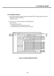
TECHNICAL BRIEF 3.5.3 Auxiliary Section 1. Two differential inputs for the battery charger current sensor CSFS CSDI CSDO AD6535 Control Serial Port AFC DAC Voltage Reference Aux ADC REFTXCM Light Controllers AFCDAC REFBB REFOUT REFCHG REF TEMP1 ...
TECHNICAL BRIEF 3.5.3 Auxiliary Section 1. Two differential inputs for the battery charger current sensor CSFS CSDI CSDO AD6535 Control Serial Port AFC DAC Voltage Reference Aux ADC REFTXCM Light Controllers AFCDAC REFBB REFOUT REFCHG REF TEMP1 ...
Service Manual
Page 34
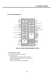
The AD6535 controls power on . - If a battery is generated and send to the AD6527B - 35 - Power up sequence logic 1. Reset is inserted, the battery powers the 8 LDOs. - AD6535 POWER MANAGEMENT SECTION 1. REFOUT is detected, the LDOs output turn on sequence 2. Then if PWRONKEY is also enabled - TECHNICAL BRIEF Figure 3-13. Power on sequence - 3.5.5 Power Management 3.
The AD6535 controls power on . - If a battery is generated and send to the AD6527B - 35 - Power up sequence logic 1. Reset is inserted, the battery powers the 8 LDOs. - AD6535 POWER MANAGEMENT SECTION 1. REFOUT is detected, the LDOs output turn on sequence 2. Then if PWRONKEY is also enabled - TECHNICAL BRIEF Figure 3-13. Power on sequence - 3.5.5 Power Management 3.
Service Manual
Page 35
... AD6537B - VAPP : supplies application co-processors such as a touch screen digitizer (3.0V, 1.8V) - VRTC : supplies the Real-Time Clock module (1.8 V, 20 A) - VBACK : charges the backup battery and supplies the RTC regulator (2.8V, 1.8V) - VMEM : supplies external memory and the interface to the external memory on the digital processor and SIM card...
... AD6537B - VAPP : supplies application co-processors such as a touch screen digitizer (3.0V, 1.8V) - VRTC : supplies the Real-Time Clock module (1.8 V, 20 A) - VBACK : charges the backup battery and supplies the RTC regulator (2.8V, 1.8V) - VMEM : supplies external memory and the interface to the external memory on the digital processor and SIM card...
Service Manual
Page 36
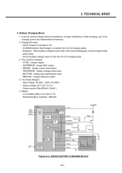
...or not - TA (Travel Adaptor) - AD6535 BATTERY CHARGING BLOCK - 37 - And the battery voltage reach to charge Lithium Ion batteries. Output current: Max 800mA ( 50mA ) 5. Standard battery: Capacity - 830mAh Figure 3-15. TECHNICAL BRIEF 3. Battery Charging Block 1. GATEDRIVE : charge DAC output ...2V the CC-CV charging starts. 3. BATTYPE : battery type identification input - Input voltage: AC 85V ~ 260V, 50~60Hz - Output voltage: DC 5.2V ( 0.2 V ) - Li-ion battery (Max 4.2V, Nom 3.7V) - Battery - Exception : When battery voltage is lower than 3.2V, the precharge(low ...
...or not - TA (Travel Adaptor) - AD6535 BATTERY CHARGING BLOCK - 37 - And the battery voltage reach to charge Lithium Ion batteries. Output current: Max 800mA ( 50mA ) 5. Standard battery: Capacity - 830mAh Figure 3-15. TECHNICAL BRIEF 3. Battery Charging Block 1. GATEDRIVE : charge DAC output ...2V the CC-CV charging starts. 3. BATTYPE : battery type identification input - Input voltage: AC 85V ~ 260V, 50~60Hz - Output voltage: DC 5.2V ( 0.2 V ) - Li-ion battery (Max 4.2V, Nom 3.7V) - Battery - Exception : When battery voltage is lower than 3.2V, the precharge(low ...
Service Manual
Page 37
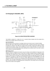
...) becomes a limiting factor of both internal power devices before switching from one power source to logic HIGH, the charge current is driven to charge the battery. USB Charge Current When the USB port is equivalent to a logic LOW when left floating. Thus, if the input voltage drops to a level that ... selects only one power source to the other to avoid a cross conduction of the charge current; Otherwise the USB input is 260mV. Thus for a single-cell Li-ion or Li-polymer battery charging circuit that the voltage difference between the USB pin and the BAT pin is less than the...
...) becomes a limiting factor of both internal power devices before switching from one power source to logic HIGH, the charge current is driven to charge the battery. USB Charge Current When the USB port is equivalent to a logic LOW when left floating. Thus, if the input voltage drops to a level that ... selects only one power source to the other to avoid a cross conduction of the charge current; Otherwise the USB input is 260mV. Thus for a single-cell Li-ion or Li-polymer battery charging circuit that the voltage difference between the USB pin and the BAT pin is less than the...
Service Manual
Page 39
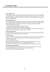
...turns off as long as given in a trickle/preconditioning mode, where the charge current is a power present, the charger will not charge the battery if the input voltage does not meet the power-good conditions. VBAT > VOS where the VOS is approximately 53mA. If power comes from excessive...VCDRL or VUSB - End-of the CHG pin status, however, the charger does not turn off when the charge current falls below the minimum battery voltage VMIN given in the electrical specification, the charger operates in the Electrical Specification table. 3. Power-Good Range Even if there is typically 14...
...turns off as long as given in a trickle/preconditioning mode, where the charge current is a power present, the charger will not charge the battery if the input voltage does not meet the power-good conditions. VBAT > VOS where the VOS is approximately 53mA. If power comes from excessive...VCDRL or VUSB - End-of the CHG pin status, however, the charger does not turn off when the charge current falls below the minimum battery voltage VMIN given in the electrical specification, the charger operates in the Electrical Specification table. 3. Power-Good Range Even if there is typically 14...
Service Manual
Page 71
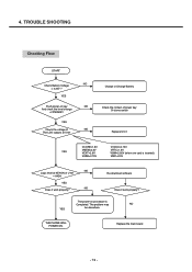
4. YES Push power-on procedure is inserted) VMIC=2.5V NO Logic level at U101 Charge or Change Battery Check the contact of power key Or dome-switch Replace U101 YES VCORE=1.8V VMEM=2.8V VEXT=2.8V VABB=2.75V VVCXO=2.75V VRTC=1.8V VSIM=2....85V (when sim card is Completed. TROUBLE SHOOTING Checking Flow START NO Check Battery Voltage > 3.35V ? Re-download software Does it work properly? THE PHONE WILL POWER ON. The power-on key NO And check the level change of PWRKEY YES Check the voltage of...
4. YES Push power-on procedure is inserted) VMIC=2.5V NO Logic level at U101 Charge or Change Battery Check the contact of power key Or dome-switch Replace U101 YES VCORE=1.8V VMEM=2.8V VEXT=2.8V VABB=2.75V VVCXO=2.75V VRTC=1.8V VSIM=2....85V (when sim card is Completed. TROUBLE SHOOTING Checking Flow START NO Check Battery Voltage > 3.35V ? Re-download software Does it work properly? THE PHONE WILL POWER ON. The power-on key NO And check the level change of PWRKEY YES Check the voltage of...
Service Manual
Page 73
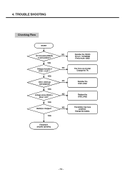
YES Charging is properly operating Resolder the CN303 Pin 4,5 : VCHARGE Pin12,19,26 : GND The TA is charged? YES Voltage at anode of order Change the TA Resolder the D401,U402 Replace the D401,U402 The battery may have problems. Change the battery. - 74 - YES NO Battery is out of NO D401 = 5.2V ? TROUBLE SHOOTING Checking Flow START NO I/O Connector(CN303) Is well-soldered ? YES NO Voltage across R408 is about 1.2V? YES D401, U402 are NO well-soldered? 4.
YES Charging is properly operating Resolder the CN303 Pin 4,5 : VCHARGE Pin12,19,26 : GND The TA is charged? YES Voltage at anode of order Change the TA Resolder the D401,U402 Replace the D401,U402 The battery may have problems. Change the battery. - 74 - YES NO Battery is out of NO D401 = 5.2V ? TROUBLE SHOOTING Checking Flow START NO I/O Connector(CN303) Is well-soldered ? YES NO Voltage across R408 is about 1.2V? YES D401, U402 are NO well-soldered? 4.
Service Manual
Page 88
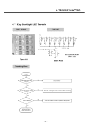
... 3 Q301 2 C319 1 2SC5585 27p R359 10 R360 10 LEBB-S14H X 8EA KEY_BACKLIGHT (WHITE LED) Main PCB START Is the voltage level VBAT 3.6-4.2V? No Charge battery No Check the soldering of Q302. 4.
... 3 Q301 2 C319 1 2SC5585 27p R359 10 R360 10 LEBB-S14H X 8EA KEY_BACKLIGHT (WHITE LED) Main PCB START Is the voltage level VBAT 3.6-4.2V? No Charge battery No Check the soldering of Q302. 4.
Service Manual
Page 89
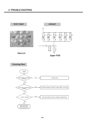
Yes Are all LEDs LD100~LD105 working ? Yes BACKLIGHT WILL WORK PROPERLY. Yes Q100 is working ? No Charge battery No Check the soldering of Q100. No Check the condition of each R or replace LEDs not working. TROUBLE SHOOTING TEST POINT CIRCUIT VBAT 47 47 ...
Yes Are all LEDs LD100~LD105 working ? Yes BACKLIGHT WILL WORK PROPERLY. Yes Q100 is working ? No Charge battery No Check the soldering of Q100. No Check the condition of each R or replace LEDs not working. TROUBLE SHOOTING TEST POINT CIRCUIT VBAT 47 47 ...
Service Manual
Page 101
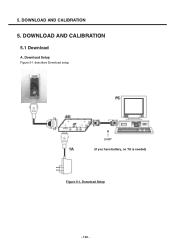
Download Setup Figure 5-1 describes Download setup UART (If you have battery, no TA is needed) Figure 5-1. DOWNLOAD AND CALIBRATION 5.1 Download A. 5. DOWNLOAD AND CALIBRATION 5. Download Setup - 102 -
Download Setup Figure 5-1 describes Download setup UART (If you have battery, no TA is needed) Figure 5-1. DOWNLOAD AND CALIBRATION 5.1 Download A. 5. DOWNLOAD AND CALIBRATION 5. Download Setup - 102 -
Service Manual
Page 106
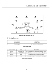
... Switch 3 Switch 4 Name ADI-REMOTE TI-REMOTE VBAT PS Description In ON state, phone is awaked. It is used TI chipset. Power is provided for phone from battery Power is used ADI chipset. It is provided for phone from Power supply Table 5-3 Jig DIP Switch - 107 - DOWNLOAD AND CALIBRATION JTAG2 JTAG1... USB MON PHONE UART TA ON OFF ADI-REMOTE POWER TI-REMOTE TA ...
... Switch 3 Switch 4 Name ADI-REMOTE TI-REMOTE VBAT PS Description In ON state, phone is awaked. It is used TI chipset. Power is provided for phone from battery Power is used ADI chipset. It is provided for phone from Power supply Table 5-3 Jig DIP Switch - 107 - DOWNLOAD AND CALIBRATION JTAG2 JTAG1... USB MON PHONE UART TA ON OFF ADI-REMOTE POWER TI-REMOTE TA ...
Service Manual
Page 107
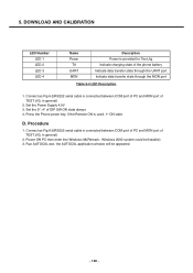
... cable is provided for Test Jig Indicate charging state of TEST JIG, in general) 2. Press the Phone power key, if the Remote ON is connected between COM port of PC and MON port of the phone battery Indicate data transfer state through the UART port Indicate data transfer state through the MON port...
... cable is provided for Test Jig Indicate charging state of TEST JIG, in general) 2. Press the Phone power key, if the Remote ON is connected between COM port of PC and MON port of the phone battery Indicate data transfer state through the UART port Indicate data transfer state through the MON port...

Service Manual
Page 124
... Tree Engineering Mode BB Test RF Test MF Mode Trace option Call Timer Fact. ENGINEERING MODE 9. C. Reset S/W Version LCD CAMERA LED BACKLIGHT BUZZER VIBRATOR ADC BATTERY AUDIO DAI BLUETOOTH SAR Test All Auto Test Backlight Buzzer Vibrator LCD Key pad MicSpkTest Camera UART On UART Off BLUETOOTH ON BLUETOOTH OFF All...
... Tree Engineering Mode BB Test RF Test MF Mode Trace option Call Timer Fact. ENGINEERING MODE 9. C. Reset S/W Version LCD CAMERA LED BACKLIGHT BUZZER VIBRATOR ADC BATTERY AUDIO DAI BLUETOOTH SAR Test All Auto Test Backlight Buzzer Vibrator LCD Key pad MicSpkTest Camera UART On UART Off BLUETOOTH ON BLUETOOTH OFF All...

