Service Manual
Page 28
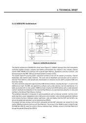
... to the terminal functions: keyboard, battery supervision, radio and display. The Digital Signal Processing (DSP) subsystem primarily hosts all the GSM terminal software, including the layer 1, 2 and 3 of AD6527B is tightly associated with on-chip system SRAM and also includes boot ROM memory with external... EBUS FLASH RF-Control MMI USC Figure 3-7. AD6527B Architecture The internal architecture of the GSM protocol stack, the MMI, and applications software such as interrupt controller, real time clock, watch dog timer, power management and a timing and control module. The code used ...
... to the terminal functions: keyboard, battery supervision, radio and display. The Digital Signal Processing (DSP) subsystem primarily hosts all the GSM terminal software, including the layer 1, 2 and 3 of AD6527B is tightly associated with on-chip system SRAM and also includes boot ROM memory with external... EBUS FLASH RF-Control MMI USC Figure 3-7. AD6527B Architecture The internal architecture of the GSM protocol stack, the MMI, and applications software such as interrupt controller, real time clock, watch dog timer, power management and a timing and control module. The code used ...
Service Manual
Page 62
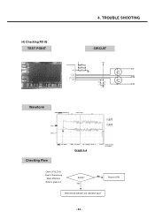
Yes No Replace U501 Redownload software and calibration again - 63 - 4. Check if there is any Major difference Refer to grapa 4-4 Similar? TROUBLE SHOOTING (4) Checking RX IQ TEST POINT Waveform CIRCUIT 1 VCC3 2 I+_TX_I+ I-_TX_I- 3 Q-_TX_Q- 4 5 Q+_TX_Q+ VCC1 6 C508 22u C509 33p C510 0.1u VBAT IP C511 39p IN QN C512 C513 C514 39p 0.1u 33p QP Checking Flow Graph 4-4 Check C512,C513.
Yes No Replace U501 Redownload software and calibration again - 63 - 4. Check if there is any Major difference Refer to grapa 4-4 Similar? TROUBLE SHOOTING (4) Checking RX IQ TEST POINT Waveform CIRCUIT 1 VCC3 2 I+_TX_I+ I-_TX_I- 3 Q-_TX_Q- 4 5 Q+_TX_Q+ VCC1 6 C508 22u C509 33p C510 0.1u VBAT IP C511 39p IN QN C512 C513 C514 39p 0.1u 33p QP Checking Flow Graph 4-4 Check C512,C513.
Service Manual
Page 69
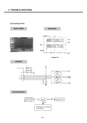
4. Yes No Replace U501 Redownload the Software And calibrate - 70 - TROUBLE SHOOTING (5) Checking TX IQ TEST POINT Waveform CIRCUIT 1 VCC3 2 I+_TX_I+ I-_TX_I- 3 Q-_TX_Q- 4 5 Q+_TX_Q+ VCC1 6 C508 22u C509 33p C510 0.1u Graph 4-9 VBAT IP C511 39p IN QN C512 C513 C514 39p 0.1u 33p QP Checking Flow Check if there is Any Major Difference Refer to Graph 4-9 Similar?
4. Yes No Replace U501 Redownload the Software And calibrate - 70 - TROUBLE SHOOTING (5) Checking TX IQ TEST POINT Waveform CIRCUIT 1 VCC3 2 I+_TX_I+ I-_TX_I- 3 Q-_TX_Q- 4 5 Q+_TX_Q+ VCC1 6 C508 22u C509 33p C510 0.1u Graph 4-9 VBAT IP C511 39p IN QN C512 C513 C514 39p 0.1u 33p QP Checking Flow Check if there is Any Major Difference Refer to Graph 4-9 Similar?
Service Manual
Page 71
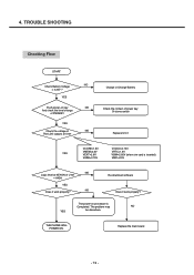
... inserted) VMIC=2.5V NO Logic level at KEYON of U101 = HIGH YES NO Does it work properly? The problem may NO YES be elsewhere. THE PHONE WILL POWER ON. Re-download software Does it work properly? 4. TROUBLE SHOOTING Checking Flow START NO Check Battery Voltage > 3.35V ?
... inserted) VMIC=2.5V NO Logic level at KEYON of U101 = HIGH YES NO Does it work properly? The problem may NO YES be elsewhere. THE PHONE WILL POWER ON. Re-download software Does it work properly? 4. TROUBLE SHOOTING Checking Flow START NO Check Battery Voltage > 3.35V ?
Service Manual
Page 97
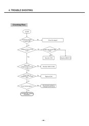
Yes Close Folder or Voltage at Pin 1 of U101 = 2.8V ? Voltage at pin 1 of U101 = 2.8V ? Yes Does it work properly ? No Resolder R202 & U200 No Replace U200 No Re-download software or Change the main board. - 98 - No No Voltage 2V8_EXTof ABB = 2.8V? Yes Yes Resolder U200 Replace ABB(U101) Open slide. TROUBLE SHOOTING Checking Flow START Check the magnet No in upper side Place the magnet Yes Voltage at Pin 6 of U200 =0V? 4. Yes FOLDER WILL WORK PROPERLY.
Yes Close Folder or Voltage at Pin 1 of U101 = 2.8V ? Voltage at pin 1 of U101 = 2.8V ? Yes Does it work properly ? No Resolder R202 & U200 No Replace U200 No Re-download software or Change the main board. - 98 - No No Voltage 2V8_EXTof ABB = 2.8V? Yes Yes Resolder U200 Replace ABB(U101) Open slide. TROUBLE SHOOTING Checking Flow START Check the magnet No in upper side Place the magnet Yes Voltage at Pin 6 of U200 =0V? 4. Yes FOLDER WILL WORK PROPERLY.
Service Manual
Page 104
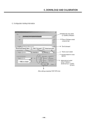
Configuration Setting Information Download speed (bps ) Start Com port End Com port USE no3.cPhreecsks Start and Wait Model DLL File select (C:\GSMULTI\Model) Phone Software select (mot,m0 file) Donít changed Frame count select ìHermesîselect in case M6100 External boot select (Only TI Model ) (External boot : G7000, G7030 ) After setting completed "OK" BTN click - 105 - DOWNLOAD AND CALIBRATION C. 5.
Configuration Setting Information Download speed (bps ) Start Com port End Com port USE no3.cPhreecsks Start and Wait Model DLL File select (C:\GSMULTI\Model) Phone Software select (mot,m0 file) Donít changed Frame count select ìHermesîselect in case M6100 External boot select (Only TI Model ) (External boot : G7000, G7030 ) After setting completed "OK" BTN click - 105 - DOWNLOAD AND CALIBRATION C. 5.
Service Manual
Page 105
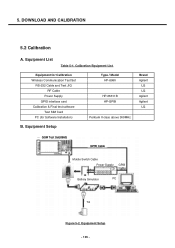
... - Equipment Setup Brand Agilent LG LG Agilent Agilent LG GSM Test Set(8960) GPIB Cable MMoboibleileSSwwitcithchCCabalbele Power Supply GPIB Cable BBatatettreyrySSimimulualtaotror PC PC TTAA Figure 5-2. Equipment for Calibration Wireless Communication Test Set RS-232 Cable and Test JIG RF Cable Power Supply GPIO interface card Calibration & Final test software Test SIM Card PC (for...
... - Equipment Setup Brand Agilent LG LG Agilent Agilent LG GSM Test Set(8960) GPIB Cable MMoboibleileSSwwitcithchCCabalbele Power Supply GPIB Cable BBatatettreyrySSimimulualtaotror PC PC TTAA Figure 5-2. Equipment for Calibration Wireless Communication Test Set RS-232 Cable and Test JIG RF Cable Power Supply GPIO interface card Calibration & Final test software Test SIM Card PC (for...
Service Manual
Page 128
... Reset) should be only used by neither engineers nor users. 9.5 Call timer [MENU 5] This menu is to set up the default value in the phone. - 129 - cannot be used during the Manufacturing process. 2 Servicemen should NOT progress this , [00:00:00]. 3) DAI DOWNLINK : Speech decoder... DAI mode off 9.6 Fact. Reset [MENU 6] This Factory Reset menu is NOT a necessary menu to be restored again. 9.7 S/W version This displays software version stored in data block. 9. ENGINEERING MODE 9.3.7 MicSpk Test The sound from MIC is recorded for Speech Transcoder and Acoustic testing. 1) All calls :...
... Reset) should be only used by neither engineers nor users. 9.5 Call timer [MENU 5] This menu is to set up the default value in the phone. - 129 - cannot be used during the Manufacturing process. 2 Servicemen should NOT progress this , [00:00:00]. 3) DAI DOWNLINK : Speech decoder... DAI mode off 9.6 Fact. Reset [MENU 6] This Factory Reset menu is NOT a necessary menu to be restored again. 9.7 S/W version This displays software version stored in data block. 9. ENGINEERING MODE 9.3.7 MicSpk Test The sound from MIC is recorded for Speech Transcoder and Acoustic testing. 1) All calls :...


