

Service Manual
Page 2
Air Conditioner Service Manual TABLE OF CONTENTS Safety Precautions...3 Dimensions ...6 Outside Dimensions ...6 Product Specifications ...7 Installation ...8 Select the Best Location ...8 Installation Check ...8 How to Secure the Drain Pipe ...8 How to Install...9 Operation ...12 Function of Controls ...12 Disassembly ...13 Mechanical Parts...13 Air handling Parts...14 Electrical Parts ...15 Refrigerating Cycle...17 Schematic Diagram...20...
Air Conditioner Service Manual TABLE OF CONTENTS Safety Precautions...3 Dimensions ...6 Outside Dimensions ...6 Product Specifications ...7 Installation ...8 Select the Best Location ...8 Installation Check ...8 How to Secure the Drain Pipe ...8 How to Install...9 Operation ...12 Function of Controls ...12 Disassembly ...13 Mechanical Parts...13 Air handling Parts...14 Electrical Parts ...15 Refrigerating Cycle...17 Schematic Diagram...20...
Service Manual
Page 3
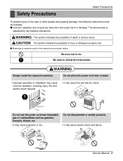
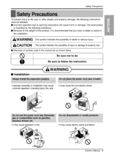
... classified by the following instructions must be followed. Be sure to property only. Do not use the power cord near a heater. • Improper assembly or installation may cause incorrect operation, including injury, fire, and electric shock hazards. • It may cause explosion or fire. Do not disassemble or modify products. •... may cause fire and electric shock. s Meanings of death or serious injury. s Incorrect operation due to ignoring instruction will cause harm or damage. WARNING Always install the expansion panel(s).
... classified by the following instructions must be followed. Be sure to property only. Do not use the power cord near a heater. • Improper assembly or installation may cause incorrect operation, including injury, fire, and electric shock hazards. • It may cause explosion or fire. Do not disassemble or modify products. •... may cause fire and electric shock. s Meanings of death or serious injury. s Incorrect operation due to ignoring instruction will cause harm or damage. WARNING Always install the expansion panel(s).
Service Manual
Page 5
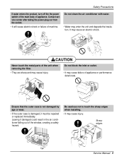
It may cause injury. CAUTION Never touch the metal parts of appliance. Be cautious not to touch the sharp edges when installing. • It may cause an electric shock. Safety Precautions If water enters the product, turn off the the power switch of the main body of ...
It may cause injury. CAUTION Never touch the metal parts of appliance. Be cautious not to touch the sharp edges when installing. • It may cause an electric shock. Safety Precautions If water enters the product, turn off the the power switch of the main body of ...
Service Manual
Page 8
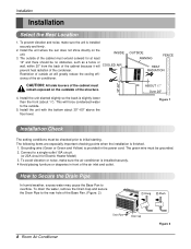
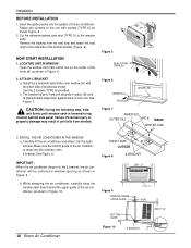
...of the cabinet because it will COOLED AIR prevent heat radiation of the structure. 4. The following items are especially important checking points when the installation is provided in front of the Base Pan. (Figure. 2) 8 Room Air Conditioner Drain Pipe Drain Cap Figure 2 To drain the water... the Drain Pipe In humid weather, excess water may cause the Base Pan to the rear hole of the air inlet and outlet. Installation Installation Select the Best Location 1. INSIDE 3. OUTSIDE AWNING FENCE HEAT RADIATION 30"-60" CAUTION: All side louvers of the air conditioner. This...
...of the cabinet because it will COOLED AIR prevent heat radiation of the structure. 4. The following items are especially important checking points when the installation is provided in front of the Base Pan. (Figure. 2) 8 Room Air Conditioner Drain Pipe Drain Cap Figure 2 To drain the water... the Drain Pipe In humid weather, excess water may cause the Base Pan to the rear hole of the air inlet and outlet. Installation Installation Select the Best Location 1. INSIDE 3. OUTSIDE AWNING FENCE HEAT RADIATION 30"-60" CAUTION: All side louvers of the air conditioner. This...
Service Manual
Page 9
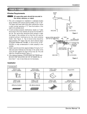
... WOOD STRIP MOUNTED ON TOP OF INNER SILL 1" MAX. 3/4" CLEARANCE INNER SILL WOOD STRIP FOR L BRACKET INDOORS STORM WINDOW FRAME OUTER SILL OUTDOORS Figure 4 Installation HARDWARE TYPE A: 11EA (SHORT SCREW) TYPE B: 5EA (WOOD SCREW) TYPE C: 3EA (L BACKET) DRAIN PIPE 10mm 16mm TYPE D: 1EA (SEAL STRIP) (... Manual 9 The upper and lower sash must open sufficiently to allow a clear vertical opening widths of 22" to 36". Installation How to Install Window Requirements NOTICE All supporting parts should be thick enough to raise the height of the window sill so that the unit can...
... WOOD STRIP MOUNTED ON TOP OF INNER SILL 1" MAX. 3/4" CLEARANCE INNER SILL WOOD STRIP FOR L BRACKET INDOORS STORM WINDOW FRAME OUTER SILL OUTDOORS Figure 4 Installation HARDWARE TYPE A: 11EA (SHORT SCREW) TYPE B: 5EA (WOOD SCREW) TYPE C: 3EA (L BACKET) DRAIN PIPE 10mm 16mm TYPE D: 1EA (SEAL STRIP) (... Manual 9 The upper and lower sash must open sufficiently to allow a clear vertical opening widths of 22" to 36". Installation How to Install Window Requirements NOTICE All supporting parts should be thick enough to raise the height of the window sill so that the unit can...
Service Manual
Page 10
...the seal strip and attach the seal strip to place bracket edge flush against back of the bottom window. (Figure. 6) NOW START INSTALLATION 1. Make sure the bottom guide of the air conditioner drops into the guides of the L bracket. IMPORTANT : When the air ...STRIP (TYPE D) Type A Figure 6 INNER SILL ROOM SIDE CENTER LINE Figure 7 INNER SILL OUTER SILL TYPE A INSIDE CENTER LINE 3. INSTALL THE AIR CONDITIONER IN THE WINDOW a. Install the L brackets behind the inner window sill, with screws (TYPE A) as shown Figure. 5. 2. Carefully lift the air conditioner and slide...
...the seal strip and attach the seal strip to place bracket edge flush against back of the bottom window. (Figure. 6) NOW START INSTALLATION 1. Make sure the bottom guide of the air conditioner drops into the guides of the L bracket. IMPORTANT : When the air ...STRIP (TYPE D) Type A Figure 6 INNER SILL ROOM SIDE CENTER LINE Figure 7 INNER SILL OUTER SILL TYPE A INSIDE CENTER LINE 3. INSTALL THE AIR CONDITIONER IN THE WINDOW a. Install the L brackets behind the inner window sill, with screws (TYPE A) as shown Figure. 5. 2. Carefully lift the air conditioner and slide...
Service Manual
Page 11
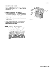
...guide panels (TYPE F) to secure them, as shown in Figure. 11. 6. Close the guide panels. L Bracket Type A Type B Figure 11 Installation Sash Seal (Type F) Service Manual 11 keeping a firm grip on the air conditioner, raise the sash, and carefully tilt the air conditioner backward, ...draining any condensate water. INSTALL THE SASH SEAL AND SASH LOCK a. Fasten the L bracket using 4 screws (TYPE B) to fill the window opening using a (TYPE A) screw, ...
...guide panels (TYPE F) to secure them, as shown in Figure. 11. 6. Close the guide panels. L Bracket Type A Type B Figure 11 Installation Sash Seal (Type F) Service Manual 11 keeping a firm grip on the air conditioner, raise the sash, and carefully tilt the air conditioner backward, ...draining any condensate water. INSTALL THE SASH SEAL AND SASH LOCK a. Fasten the L bracket using 4 screws (TYPE B) to fill the window opening using a (TYPE A) screw, ...
Service Manual
Page 12
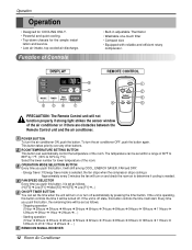
... automatically control the temperature of the room. Energy Saver: If Energy Save mode is off automatically by 1°C) Select the lower number for the simple instal- Starting operation (1Hour ➔ 2Hours ➔ 3Hours ➔ 4Hours ➔ 5Hours ➔ 6Hours ➔ 7Hours ➔ 8Hours ➔ 9Hours ➔ 10Hours ➔ 11Hours ➔ 12Hours...
... automatically control the temperature of the room. Energy Saver: If Energy Save mode is off automatically by 1°C) Select the lower number for the simple instal- Starting operation (1Hour ➔ 2Hours ➔ 3Hours ➔ 4Hours ➔ 5Hours ➔ 6Hours ➔ 7Hours ➔ 8Hours ➔ 9Hours ➔ 10Hours ➔ 11Hours ➔ 12Hours...
Service Manual
Page 13
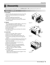
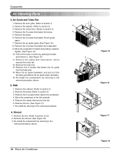
Mechanical Parts 1. Open the lnlet grille downward and remove the air filter. 2. Re-install the components by referring to the removal procedure, above . Remove the cabinet. 5. Re-install the components by referring to the removal procedure, above . 2. Disconnect the grounding screw from the ...2. Control Box 1. Remove the nut that fastens the front grille.(See Figure 12) 3. Front Grille 1. Remove the terminal cover. 9. Re-install the components by placing a 20,000 ohm resistor across the capacitor terminals. 11. Remove the front grille.(There are 4 hooks.) 5. Remove ...
Mechanical Parts 1. Open the lnlet grille downward and remove the air filter. 2. Re-install the components by referring to the removal procedure, above . Remove the cabinet. 5. Re-install the components by referring to the removal procedure, above . 2. Disconnect the grounding screw from the ...2. Control Box 1. Remove the nut that fastens the front grille.(See Figure 12) 3. Front Grille 1. Remove the terminal cover. 9. Re-install the components by placing a 20,000 ohm resistor across the capacitor terminals. 11. Remove the front grille.(There are 4 hooks.) 5. Remove ...
Service Manual
Page 14
...15) 8. Move the air guide backward, and pull out from the base pan. 14. Re-install the components by referring to section 2) 3. Remove the 5 screws which secures the turbo fan. 12. Re-install the components by referring to section 3) 4. Disassembly Air Handling Parts 4. Remove the cabinet. (...front grille. (Refer to section 4) 3. Remove the 2 screws that fasten the evaporator. 9. Remove the 2 screws that fasten the air guide upper. 7. Re-install by pushing the tabs and remove it upward slightly. (See Figure 16) 10. Remove the fan. (See Figure 17) 7. Remove the fan. (Refer to ...
...15) 8. Move the air guide backward, and pull out from the base pan. 14. Re-install the components by referring to section 2) 3. Remove the 5 screws which secures the turbo fan. 12. Re-install the components by referring to section 3) 4. Disassembly Air Handling Parts 4. Remove the cabinet. (...front grille. (Refer to section 4) 3. Remove the 2 screws that fasten the evaporator. 9. Remove the 2 screws that fasten the air guide upper. 7. Re-install by pushing the tabs and remove it upward slightly. (See Figure 16) 10. Remove the fan. (See Figure 17) 7. Remove the fan. (Refer to ...

Service Manual
Page 15
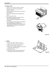
.... (See Figure 21) 3. Discharge the refrigerant system using a FreonTM Recovery System. Remove the overload protector. (Refer to section 2) 2. Re-install the components by referring to the removal procedure, above. 9. Remove the cabinet. (Refer to section 7) 4. Remove all the leads of capacitor ... procedure, above . Remove the compressor. (See Figure 20) 7. Remove the control box. (Refer to the removal procedure, above . 8. Re-install the components by referring to section 3) 2. Remove the nut that fastens the terminal cover. 3. Remove the 3 nuts and the 3 washers which ...
.... (See Figure 21) 3. Discharge the refrigerant system using a FreonTM Recovery System. Remove the overload protector. (Refer to section 2) 2. Re-install the components by referring to the removal procedure, above. 9. Remove the cabinet. (Refer to section 7) 4. Remove all the leads of capacitor ... procedure, above . Remove the compressor. (See Figure 20) 7. Remove the control box. (Refer to the removal procedure, above . 8. Re-install the components by referring to section 3) 2. Remove the nut that fastens the terminal cover. 3. Remove the 3 nuts and the 3 washers which ...
Service Manual
Page 16
... procedure, above .(See Figure 23) 16 Room Air Conditioner Figure 22 Figure 23 Open the top cover from the air guide. (See Figure 23) 5. Re-install the components by referring to section 9) 3. Remove the turbo fan. (Refer to section 2) 2. Remove the cabinet. (Refer to section 4) 3. Remove the 4 ...box. (Refer to the removal procedure, above . (Use only one ground-marked hole for ground connection.) 7. Pull out the power cord. 6. Re-install the component by the special cord. (The special cord means the cord which has the same specification marked on the supply cord attached at the...
... procedure, above .(See Figure 23) 16 Room Air Conditioner Figure 22 Figure 23 Open the top cover from the air guide. (See Figure 23) 5. Re-install the components by referring to section 9) 3. Remove the turbo fan. (Refer to section 2) 2. Remove the cabinet. (Refer to section 4) 3. Remove the 4 ...box. (Refer to the removal procedure, above . (Use only one ground-marked hole for ground connection.) 7. Pull out the power cord. 6. Re-install the component by the special cord. (The special cord means the cord which has the same specification marked on the supply cord attached at the...
Service Manual
Page 17
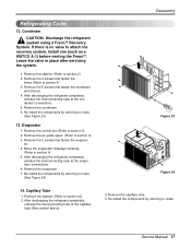
... components by referring to notes. (See Figure 23) 13. Leave the valve in place after servicing the system. 1. Re-install the components by referring to section 4) 3. Remove the air guide upper. (Refer to section s2) 2. After discharging the refrigerant completely, ...Service Manual 17 If there is no valve to section 3) 2. Remove the control box.(Refer to attach the recovery system, install one (such as a WATCO A-1) before venting the FreonTM. Re-install the components by referring to notes. Remove the 4 screws that fasten the brace.(Refer to notes. (See Figure 24) ...
... components by referring to notes. (See Figure 23) 13. Leave the valve in place after servicing the system. 1. Re-install the components by referring to section 4) 3. Remove the air guide upper. (Refer to section s2) 2. After discharging the refrigerant completely, ...Service Manual 17 If there is no valve to section 3) 2. Remove the control box.(Refer to attach the recovery system, install one (such as a WATCO A-1) before venting the FreonTM. Re-install the components by referring to notes. Remove the 4 screws that fasten the brace.(Refer to notes. (See Figure 24) ...

Service Manual
Page 18
...minutes, until the balance of the charge is in the system. 6) When satisfied the unit is now pulling through the access valve which you installed as the system was opened. 2) Connect the charging cylinder as shown in the High-side, the balance will keep oil from the pinch-... and entire system. Recharge as follows : 1) Refrigeration cycle systems are charged from the vacuum pump and place it on to attach the recovery system, install one (such as illustrated figure 25A. 2) Start the vacuum pump, slowly open manifold valves A and B with two full turns counterclockwise and leave the...
...minutes, until the balance of the charge is in the system. 6) When satisfied the unit is now pulling through the access valve which you installed as the system was opened. 2) Connect the charging cylinder as shown in the High-side, the balance will keep oil from the pinch-... and entire system. Recharge as follows : 1) Refrigeration cycle systems are charged from the vacuum pump and place it on to attach the recovery system, install one (such as illustrated figure 25A. 2) Start the vacuum pump, slowly open manifold valves A and B with two full turns counterclockwise and leave the...
Service Manual
Page 38
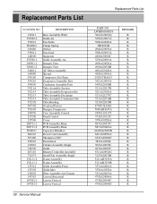
... Panel,Control Cover PCB Assembly,Main PCB Assembly,Main Capacitor,Film,Box Power Cord Assembly Thermistor,NTC Escutcheon Cabinet Assembly,Single Guide Remote Controller Assembly Install Part Assembly,Single Frame Assembly Frame Assembly Grille Assembly,Front Grille,Inlet Filter Assembly,Air Cleaner Louver,Horizontal Louver,Vertical Louver,Vertical 38 Service Manual...
... Panel,Control Cover PCB Assembly,Main PCB Assembly,Main Capacitor,Film,Box Power Cord Assembly Thermistor,NTC Escutcheon Cabinet Assembly,Single Guide Remote Controller Assembly Install Part Assembly,Single Frame Assembly Frame Assembly Grille Assembly,Front Grille,Inlet Filter Assembly,Air Cleaner Louver,Horizontal Louver,Vertical Louver,Vertical 38 Service Manual...
Owners Manual
Page 2
...'ll flr_J many answers to ensure that they do not play with the air conditioner. ,ff the power cord requires replacement have an Authorized Servicer install an exact rep|acement part. , |nstallation work must he performed in the chin1 d troubleshooting tips, I_ you _ev#w ou_ chart of this unit...
...'ll flr_J many answers to ensure that they do not play with the air conditioner. ,ff the power cord requires replacement have an Authorized Servicer install an exact rep|acement part. , |nstallation work must he performed in the chin1 d troubleshooting tips, I_ you _ev#w ou_ chart of this unit...
Owners Manual
Page 3
.... The seriousness is classified b,y the foi]]o,wing indications. [] B_ause of the weight of the product, it is recommend_ that you have a hel_r to do. mi installation * Improper as_mbly or ins_lfation rray _use inco_ operation, including iniury, fire, and • It may cau_ fire and _ectric sh_ • It may _u_ ex...
.... The seriousness is classified b,y the foi]]o,wing indications. [] B_ause of the weight of the product, it is recommend_ that you have a hel_r to do. mi installation * Improper as_mbly or ins_lfation rray _use inco_ operation, including iniury, fire, and • It may cau_ fire and _ectric sh_ • It may _u_ ex...

Owners Manual
Page 5
... may cause failure of appliance or performance • IIfthe outer case is damaged, must be repaired or replaced immediately. It may cause an electric shock.. [] Installation ,CC.UT,O.h * They are sharp and may cause inju_. , It may cause explosion, fire, and burn. * The air co,nd_ioner must be operated in the...
... may cause failure of appliance or performance • IIfthe outer case is damaged, must be repaired or replaced immediately. It may cause an electric shock.. [] Installation ,CC.UT,O.h * They are sharp and may cause inju_. , It may cause explosion, fire, and burn. * The air co,nd_ioner must be operated in the...
Owners Manual
Page 7
... cord. They should be written on while cleaning inner parts o,f the unit. If the power co_d is damaged and requires replacement, Ihave an Authorized Servicer install an exact replacement part. For repair .and maintenance, contact an Authorized Service Center. Plug in the power cord properly. 2. When cleaning the unit, first make...
... cord. They should be written on while cleaning inner parts o,f the unit. If the power co_d is damaged and requires replacement, Ihave an Authorized Servicer install an exact replacement part. For repair .and maintenance, contact an Authorized Service Center. Plug in the power cord properly. 2. When cleaning the unit, first make...
Owners Manual
Page 9
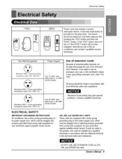
... _se, The device should be tes,t_ on 230, 208, and 2_I208 Volt units Owner, s' Manual 9 A _st and reset button is not present, one must _ installed by a qualified e]edrician in a_danoe with the National Eliectfi_J C_e and ]_ _es, and ordinances. ckcutt: breaker. Standa#d 25OV, 3-wire grounding receptac_,e rated 15A, 250V AC...
... _se, The device should be tes,t_ on 230, 208, and 2_I208 Volt units Owner, s' Manual 9 A _st and reset button is not present, one must _ installed by a qualified e]edrician in a_danoe with the National Eliectfi_J C_e and ]_ _es, and ordinances. ckcutt: breaker. Standa#d 25OV, 3-wire grounding receptac_,e rated 15A, 250V AC...


