
Service Manual
Page 2
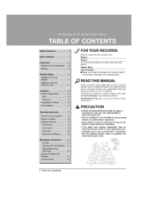
Air Conditioner Service Manual TABLE OF CONTENTS Safety Precautions...3 Dimensions ...6 Outside Dimensions ...6 Product Specifications ...7 Installation ...8 Select the Best Location ...8 Installation Check ...8 How to Secure the Drain Pipe ...8 How to Install...9 Operation ...12 Function of Controls ...12 Disassembly ...13 Mechanical Parts...13 Air handling Parts...14 Electrical Parts ...15 Refrigerating Cycle...17 Schematic Diagram...20 Electronic Control Device...20 Wiring Diagram...21 Components Location ...22 Troubleshooting Guide ...23 Pipeing System ...23 Troubleshooting Guide ...24 ...
Air Conditioner Service Manual TABLE OF CONTENTS Safety Precautions...3 Dimensions ...6 Outside Dimensions ...6 Product Specifications ...7 Installation ...8 Select the Best Location ...8 Installation Check ...8 How to Secure the Drain Pipe ...8 How to Install...9 Operation ...12 Function of Controls ...12 Disassembly ...13 Mechanical Parts...13 Air handling Parts...14 Electrical Parts ...15 Refrigerating Cycle...17 Schematic Diagram...20 Electronic Control Device...20 Wiring Diagram...21 Components Location ...22 Troubleshooting Guide ...23 Pipeing System ...23 Troubleshooting Guide ...24 ...
Service Manual
Page 5
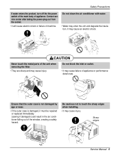
... after taking the power-plug out from the socket. • It will cause electric shock or failure of the unit when removing the filter. • They are sharp and may cause injury. Do not block ...clean the air conditioner with water. • Water may cause an electric shock. Sharp edges Service Manual 5 It may enter the unit and degrade the insulation. CAUTION Never touch the metal parts of machine. Safety Precautions If water enters the product, turn off the the power switch of the main body of appliance or performance deteriorate. Leaving it must be repaired or replaced...
... after taking the power-plug out from the socket. • It will cause electric shock or failure of the unit when removing the filter. • They are sharp and may cause injury. Do not block ...clean the air conditioner with water. • Water may cause an electric shock. Sharp edges Service Manual 5 It may enter the unit and degrade the insulation. CAUTION Never touch the metal parts of machine. Safety Precautions If water enters the product, turn off the the power switch of the main body of appliance or performance deteriorate. Leaving it must be repaired or replaced...
Service Manual
Page 7
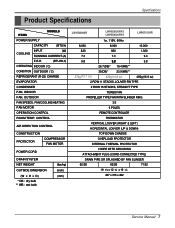
... REMOTE CONTROLLER THERMISTOR VERTICAL LOUVER (RIGHT & LEFT) HORIZONTAL LOUVER (UP & DOWN) TOP DOWN CHASSIS OVERLOAD PROTECTOR INTERNAL THERMAL PROTECTOR 3 WIRE WITH GROUDING ATTACHMENT PLUG (CORD-CONNECTED TYPE) DRAIN PIPE OR SPLASHED BY FAN SLINGER 62/28 62/28 71/32 19 9/16 x 12 3/8 x 19 3/8 497 x 315 x 492 Service Manual 7 Product Specifications Specfications ITEMS MODELS POWER SUPPLY CAPACITY (BTU/h) INPUT (W) COOLING RUNNING CURRENT (A) E.E.R (BTU/W.h) OPERATING INDOOR ( C) CONDITION OUTDOOR ( C) REFRIGERANT (R-22) CHARGE EVAPORATOR CONDENSER FAN, INDOOR...
... REMOTE CONTROLLER THERMISTOR VERTICAL LOUVER (RIGHT & LEFT) HORIZONTAL LOUVER (UP & DOWN) TOP DOWN CHASSIS OVERLOAD PROTECTOR INTERNAL THERMAL PROTECTOR 3 WIRE WITH GROUDING ATTACHMENT PLUG (CORD-CONNECTED TYPE) DRAIN PIPE OR SPLASHED BY FAN SLINGER 62/28 62/28 71/32 19 9/16 x 12 3/8 x 19 3/8 497 x 315 x 492 Service Manual 7 Product Specifications Specfications ITEMS MODELS POWER SUPPLY CAPACITY (BTU/h) INPUT (W) COOLING RUNNING CURRENT (A) E.E.R (BTU/W.h) OPERATING INDOOR ( C) CONDITION OUTDOOR ( C) REFRIGERANT (R-22) CHARGE EVAPORATOR CONDENSER FAN, INDOOR...
Service Manual
Page 8
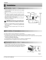
.... (Figure. 2) 8 Room Air Conditioner Drain Pipe Drain Cap Figure 2 To avoid vibration or noise, make sure the unit is installed securely. 4 Avoid placing furniture or draperies in the power cord. OUTSIDE AWNING FENCE HEAT RADIATION 30"-60" CAUTION: All side louvers of the condenser. Installation Installation Select the Best Location 1. This will greatly reduce the cooling effi- To prevent vibration and noise, make sure the air conditioner is installed securely and...
.... (Figure. 2) 8 Room Air Conditioner Drain Pipe Drain Cap Figure 2 To avoid vibration or noise, make sure the unit is installed securely. 4 Avoid placing furniture or draperies in the power cord. OUTSIDE AWNING FENCE HEAT RADIATION 30"-60" CAUTION: All side louvers of the condenser. Installation Installation Select the Best Location 1. This will greatly reduce the cooling effi- To prevent vibration and noise, make sure the air conditioner is installed securely and...
Service Manual
Page 12
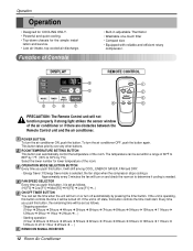
...other buttons. Operation Operation • Designed for COOLING ONLY. • Powerful and quiet cooling. • Top-down chassis for lower temperature of the room. lation and service. • Low air-intake, top cooled-air discharge. Function of the air conditioner or if there are obstacles between the Remote Control unit and the air conditioner. DISPLAY Cool Energy Saver F1 LOW F2 MED F3 HIGH 'F 6 Fan Dry Timer TEMP 2 MODE TIMER FAN SPEED POWER 3 5 4 1 REMOTE CONTROL Power 1 Temp 2 Fan Speed 4 Timer Mode 5 3 PRECAUTION: The Remote Control unit will be set as...
...other buttons. Operation Operation • Designed for COOLING ONLY. • Powerful and quiet cooling. • Top-down chassis for lower temperature of the room. lation and service. • Low air-intake, top cooled-air discharge. Function of the air conditioner or if there are obstacles between the Remote Control unit and the air conditioner. DISPLAY Cool Energy Saver F1 LOW F2 MED F3 HIGH 'F 6 Fan Dry Timer TEMP 2 MODE TIMER FAN SPEED POWER 3 5 4 1 REMOTE CONTROL Power 1 Temp 2 Fan Speed 4 Timer Mode 5 3 PRECAUTION: The Remote Control unit will be set as...

Service Manual
Page 18
... is used, just crack valves A and B for 20 to attach the recovery system, install one (such as illustrated figure 25A. 2) Start the vacuum pump, slowly open , discharge the hose at ...leak or moisture remaining in place after servicing the system. 2. Open valve C. Disassembly NOTICE - When replacing the refrigeration cycle, be put in the suction line through valves A and B up to set for a while, and then test the leakage of the refrigeration cycle. 1. After discharging the unit completely, remove the desired component, and unbraze the pinch-off connection. 18 Room Air Conditioner...
... is used, just crack valves A and B for 20 to attach the recovery system, install one (such as illustrated figure 25A. 2) Start the vacuum pump, slowly open , discharge the hose at ...leak or moisture remaining in place after servicing the system. 2. Open valve C. Disassembly NOTICE - When replacing the refrigeration cycle, be put in the suction line through valves A and B up to set for a while, and then test the leakage of the refrigeration cycle. 1. After discharging the unit completely, remove the desired component, and unbraze the pinch-off connection. 18 Room Air Conditioner...
Service Manual
Page 20
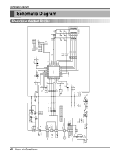
Schematic Diagram Schematic Diagram Electronic Control Device 20 Room Air Conditioner CN-TELE SMW200-03 (RD) 33 22 11 5V C01T 0.1 50V PIPE-TH CN-TH2 SMW250-02 11 22 C02T 0.001 D01T 1N4148 Q04T A104M Q01T C104M 5V Q03T C104M 5V Q02T A104M R01T 1K Rx C03T 0.001 25V Tx J7 11 2 12 1 ROOM... Model Auto Restart Non Auto Restart EEPROM CAT93C46 1 A0 Vcc 8 2 A1 WP 7 3 A2 SCL 6 4 GND SDA 5 EEPROM R04P O X X O R04P 5V R02P R03P 20K 20K Option2 Option1 Pipe TH Room TH VAref VSS Osc out Osc in /Reset TEST HVB SW2 SW1 S/V4WAY FAN MOTOR CAPACITOR FAN C HERM MAIN POWER COMP...
Schematic Diagram Schematic Diagram Electronic Control Device 20 Room Air Conditioner CN-TELE SMW200-03 (RD) 33 22 11 5V C01T 0.1 50V PIPE-TH CN-TH2 SMW250-02 11 22 C02T 0.001 D01T 1N4148 Q04T A104M Q01T C104M 5V Q03T C104M 5V Q02T A104M R01T 1K Rx C03T 0.001 25V Tx J7 11 2 12 1 ROOM... Model Auto Restart Non Auto Restart EEPROM CAT93C46 1 A0 Vcc 8 2 A1 WP 7 3 A2 SCL 6 4 GND SDA 5 EEPROM R04P O X X O R04P 5V R02P R03P 20K 20K Option2 Option1 Pipe TH Room TH VAref VSS Osc out Osc in /Reset TEST HVB SW2 SW1 S/V4WAY FAN MOTOR CAPACITOR FAN C HERM MAIN POWER COMP...

Service Manual
Page 21
ASSEMBLY BK RD 3 COMP. DESCRIPTION 1 MOTOR ASSY 2 CAPACITOR 3 COMPRESSOR 4 OVERLOAD PROTECTOR 5 DC PCB ASSEMBLY 6 AC PCB ASSEMBLY 7 THERMISTOR 8 PLASMA FILTER ASSY S: Service Parts N: Non Service Parts Q'TY PER SET 1 1 1 1 1 1 1 1 REMARKS S S S S S S S S Service Manual 21 Wiring Diagram Schematic Diagram 1 BK CN-MOTOR CN-AC/DC CN-AC/DC GN/YL BL 5 (GN) MOTOR RD YL DC PCB OR ASSEMBLY RY-LOW RY-MED RY-HI CAPACITOR CN-TH1 YL 2 F POWER 7 C OR(BR) TRANS BK...
ASSEMBLY BK RD 3 COMP. DESCRIPTION 1 MOTOR ASSY 2 CAPACITOR 3 COMPRESSOR 4 OVERLOAD PROTECTOR 5 DC PCB ASSEMBLY 6 AC PCB ASSEMBLY 7 THERMISTOR 8 PLASMA FILTER ASSY S: Service Parts N: Non Service Parts Q'TY PER SET 1 1 1 1 1 1 1 1 REMARKS S S S S S S S S Service Manual 21 Wiring Diagram Schematic Diagram 1 BK CN-MOTOR CN-AC/DC CN-AC/DC GN/YL BL 5 (GN) MOTOR RD YL DC PCB OR ASSEMBLY RY-LOW RY-MED RY-HI CAPACITOR CN-TH1 YL 2 F POWER 7 C OR(BR) TRANS BK...
Service Manual
Page 24
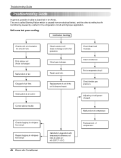
..., and the other is beyond repair. Unit runs but poor cooling. Obstruction at air outlet Correct above trouble Check outdoor coil (heat exchanger) & the fan operation. Check clogging in refrigeration circuit. 24 Room Air Conditioner Satisfactory operation with temperature difference of inlet & outlet air ; 44~50°F(7~10°C) Replacement of compressor. Repair gas leak. Ineffective Cooling Check cold air circulation for smooth flow. Dirty indoor coil (Heat exchanger) Malfunction of fan Clogged of air filter. Check gas leakage. Not on...
..., and the other is beyond repair. Unit runs but poor cooling. Obstruction at air outlet Correct above trouble Check outdoor coil (heat exchanger) & the fan operation. Check clogging in refrigeration circuit. 24 Room Air Conditioner Satisfactory operation with temperature difference of inlet & outlet air ; 44~50°F(7~10°C) Replacement of compressor. Repair gas leak. Ineffective Cooling Check cold air circulation for smooth flow. Dirty indoor coil (Heat exchanger) Malfunction of fan Clogged of air filter. Check gas leakage. Not on...
Service Manual
Page 25
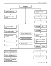
... wiring. Replacement Improper thermostat setting. Irregular motor insulation ( ). Check of power voltage. Drop of control switch setting. Defect of power source. Fails to Start Troubleshooting Guide Check of compressor capacitor. Check circuit breaker and fuse. Loose terminal connection. Gas leakage of feeler bulb of thermostat Check of compressor (Motor damaged) Regular but fails to start . Irregular motor resistance ( ) Irregular motor insulation ( ) Replacement of control switch. Service Manual 25 Defect of fan motor capacitor. Compressor only fails to start...
... wiring. Replacement Improper thermostat setting. Irregular motor insulation ( ). Check of power voltage. Drop of control switch setting. Defect of power source. Fails to Start Troubleshooting Guide Check of compressor capacitor. Check circuit breaker and fuse. Loose terminal connection. Gas leakage of feeler bulb of thermostat Check of compressor (Motor damaged) Regular but fails to start . Irregular motor resistance ( ) Irregular motor insulation ( ) Replacement of control switch. Service Manual 25 Defect of fan motor capacitor. Compressor only fails to start...

Service Manual
Page 27
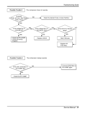
... RY-COMP. • Connect LEAD Wire to lower Number. Service Manual 27 to RY-COMP again. YES • Replace IC01M. Is the voltage No.10 NO of NO IC01M DC 12V? NO Does the Unit delay for 3 minutes? Troubleshooting Guide Is setting Temp. YES • Wait 3 Minutes. • Replace MAIN PCB Ass'y. Possible Trouble 3 The compressor always operate. Is the voltage N0.9 of IC01M...
... RY-COMP. • Connect LEAD Wire to lower Number. Service Manual 27 to RY-COMP again. YES • Replace IC01M. Is the voltage No.10 NO of NO IC01M DC 12V? NO Does the Unit delay for 3 minutes? Troubleshooting Guide Is setting Temp. YES • Wait 3 Minutes. • Replace MAIN PCB Ass'y. Possible Trouble 3 The compressor always operate. Is the voltage N0.9 of IC01M...
Service Manual
Page 28
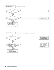
... OWNER'S MANUAL. • Set the mode key to Energy Saver mode. • Check the Energy Saver mode key. • Check the pattern of IC01M DC 12V? Is the voltage NO.1 or 2 or 4 NO of AC & DC PCB. 28 Room Air Conditioner Is the mode NO key pushed once more from cool mode? YES Is the voltage No.3 of NO CN-AC/DC of IC01M 0V? Troubleshooting Guide Possible Trouble 4 FAN...
... OWNER'S MANUAL. • Set the mode key to Energy Saver mode. • Check the Energy Saver mode key. • Check the pattern of IC01M DC 12V? Is the voltage NO.1 or 2 or 4 NO of AC & DC PCB. 28 Room Air Conditioner Is the mode NO key pushed once more from cool mode? YES Is the voltage No.3 of NO CN-AC/DC of IC01M 0V? Troubleshooting Guide Possible Trouble 4 FAN...
Service Manual
Page 31
... the RY-COMP. • Connect LEAD Wire to lower Number. NO NO Is the Unit for 3 minutes delay? Is the voltage N0.9 of IC01M DC 12V? Service Manual 31 set lower than Room NO Temp.-0.5°C? YES • Wait 3 Minutes. • Replace AC PCB Ass'y. Troubleshooting Guide Is desired Temp. Possible Trouble 3 The compressor always operate. Possible Trouble 2 The compressor does not operate. YES • Check the RY...
... the RY-COMP. • Connect LEAD Wire to lower Number. NO NO Is the Unit for 3 minutes delay? Is the voltage N0.9 of IC01M DC 12V? Service Manual 31 set lower than Room NO Temp.-0.5°C? YES • Wait 3 Minutes. • Replace AC PCB Ass'y. Troubleshooting Guide Is desired Temp. Possible Trouble 3 The compressor always operate. Possible Trouble 2 The compressor does not operate. YES • Check the RY...
Service Manual
Page 35
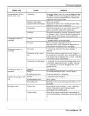
..., open . If loose, repair or replace. Close if open , or damaged. Troubleshooting Guide COMPLAINT CAUSE REMEDY Compressor will increase, causing the compressor to overload. Air filter ing Exhaust damper door Unit undersized Excessive noise Turbo or fan Copper tubing Check the TEMP control. Check overload, if externally mounted. inspect the interior surface of manufacturers rating. Straighten the fins or replace the coil. If open . (If the compressor temperature is high, remove the overload, cool it...
..., open . If loose, repair or replace. Close if open , or damaged. Troubleshooting Guide COMPLAINT CAUSE REMEDY Compressor will increase, causing the compressor to overload. Air filter ing Exhaust damper door Unit undersized Excessive noise Turbo or fan Copper tubing Check the TEMP control. Check overload, if externally mounted. inspect the interior surface of manufacturers rating. Straighten the fins or replace the coil. If open . (If the compressor temperature is high, remove the overload, cool it...
Service Manual
Page 38
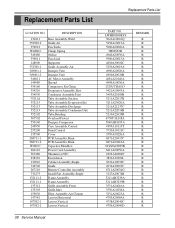
...,Suction Tube Assembly,Evaporator(In) Tube Assembly,Discharge Tube Assembly,Condenser(Out) Tube,Bending Overload Protect Damper,Compressor Case Assembly,Control Panel,Control Cover PCB Assembly,Main PCB Assembly,Main Capacitor,Film,Box Power Cord Assembly Thermistor,NTC Escutcheon Cabinet Assembly,Single Guide Remote Controller Assembly Install Part Assembly,Single Frame Assembly Frame Assembly Grille Assembly,Front Grille,Inlet Filter Assembly,Air Cleaner Louver,Horizontal Louver,Vertical Louver,Vertical 38 Service Manual Replacement Parts List PART NO.
...,Suction Tube Assembly,Evaporator(In) Tube Assembly,Discharge Tube Assembly,Condenser(Out) Tube,Bending Overload Protect Damper,Compressor Case Assembly,Control Panel,Control Cover PCB Assembly,Main PCB Assembly,Main Capacitor,Film,Box Power Cord Assembly Thermistor,NTC Escutcheon Cabinet Assembly,Single Guide Remote Controller Assembly Install Part Assembly,Single Frame Assembly Frame Assembly Grille Assembly,Front Grille,Inlet Filter Assembly,Air Cleaner Louver,Horizontal Louver,Vertical Louver,Vertical 38 Service Manual Replacement Parts List PART NO.
Owners Manual
Page 2
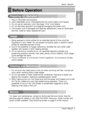
... for repair or maintenance of this pa_ in t_ _ent you need it to prove date of purchase or for use and maintain your receipt to ensure that they do not play with the air conditioner. ,ff the power cord requires replacement have an Authorized Servicer install an exact rep|acement part. , |nstallation work must he performed in accordance with the Nations| E_ectric Code...
... for repair or maintenance of this pa_ in t_ _ent you need it to prove date of purchase or for use and maintain your receipt to ensure that they do not play with the air conditioner. ,ff the power cord requires replacement have an Authorized Servicer install an exact rep|acement part. , |nstallation work must he performed in accordance with the Nations| E_ectric Code...
Owners Manual
Page 7
... not touch the metal parts of oxygen deficiency, ventilate the room when used together with stoves or other heating devices, 3 Do not use this manual. Owner_ Manual 7 Ovedoadiing the line could Ibe hazardous to , p,ossible electric shock. 3. Do not start/stop operation by plugging/unplugging the power cord. 5. There iisa possibility of this air conditioner for an extended p,eriodl of tiime. 2. Due to direct aidlow for non...
... not touch the metal parts of oxygen deficiency, ventilate the room when used together with stoves or other heating devices, 3 Do not use this manual. Owner_ Manual 7 Ovedoadiing the line could Ibe hazardous to , p,ossible electric shock. 3. Do not start/stop operation by plugging/unplugging the power cord. 5. There iisa possibility of this air conditioner for an extended p,eriodl of tiime. 2. Due to direct aidlow for non...
Owners Manual
Page 23
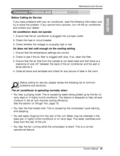
... days. If so, clean the filter. 3. Before calling for any source of the air conditioner and the wall or fence behind it. 4. This is clogged with your air conditioner, read the following list of the unit. • You hear the fan running while the compressor is caused by the fan on the cooling setting 1. Owner_ Manual Check the fuse or circuit breaker, 3. Check to see water dripping from the...
... days. If so, clean the filter. 3. Before calling for any source of the air conditioner and the wall or fence behind it. 4. This is clogged with your air conditioner, read the following list of the unit. • You hear the fan running while the compressor is caused by the fan on the cooling setting 1. Owner_ Manual Check the fuse or circuit breaker, 3. Check to see water dripping from the...
Owners Manual
Page 24
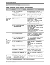
... house fuse/circuit obrrearekseert bthoex barnedakerer.place the fuse If power failure occurs, turn the mode control to Off. If the RESET bu_on will not stay engaged, discontinue use d the air conditioner and contact a qualified service technician. maximum cooling. Maintenanceand Servic_ The air cond#ioner may be set high enough. - _ _e- hot. [] Cold air is escaping. [] Coding coils have iced up [] Ice blocks the air flow and from cooling the room Make...
... house fuse/circuit obrrearekseert bthoex barnedakerer.place the fuse If power failure occurs, turn the mode control to Off. If the RESET bu_on will not stay engaged, discontinue use d the air conditioner and contact a qualified service technician. maximum cooling. Maintenanceand Servic_ The air cond#ioner may be set high enough. - _ _e- hot. [] Cold air is escaping. [] Coding coils have iced up [] Ice blocks the air flow and from cooling the room Make...
Owners Manual
Page 52
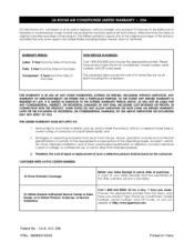
... the menu, and have product type (Room Air Conditioner), model number, serial number, and ZIP code ready, The warranted parts including labor covers the cost of Purchase. Patent No. ' Us 6, 412, 298 P/No.: 3828A21004G Printed in the Operating Guide, accident, vermin, fire, flood, improper installation, acts of God, unauthorized modification or alteration, incorrect electrical current or voltage, or commercial use, or use during the warranty period set forth below, effective from...
... the menu, and have product type (Room Air Conditioner), model number, serial number, and ZIP code ready, The warranted parts including labor covers the cost of Purchase. Patent No. ' Us 6, 412, 298 P/No.: 3828A21004G Printed in the Operating Guide, accident, vermin, fire, flood, improper installation, acts of God, unauthorized modification or alteration, incorrect electrical current or voltage, or commercial use, or use during the warranty period set forth below, effective from...


