Service Manual
Page 4
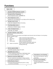
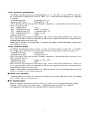
...Operation Mode • Intermittent operation of fan at the desired position or swing up during the system operation. Natural Air Control by Remote controller Sensing the Room Temperature • Room temperature sensor. (THERMISTOR) Room temperature control • Maintains the room temperature in ... • The unit will be set at low speed. Sleep Mode Auto Control • The fan is automatically switched from the remote control.(Signal receiving sound: two short beeps or one long beep.) Operation Indication Lamps On/Off : Lights up during defrosting. Timer ...
...Operation Mode • Intermittent operation of fan at the desired position or swing up during the system operation. Natural Air Control by Remote controller Sensing the Room Temperature • Room temperature sensor. (THERMISTOR) Room temperature control • Maintains the room temperature in ... • The unit will be set at low speed. Sleep Mode Auto Control • The fan is automatically switched from the remote control.(Signal receiving sound: two short beeps or one long beep.) Operation Indication Lamps On/Off : Lights up during defrosting. Timer ...
Service Manual
Page 5
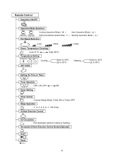
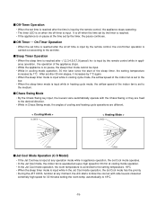
Remote Control Operation ON/OFF Operation Mode Selection (Cooling (Heating model only) model only) Cooling Operation Mode.( ) Healthy Dehumidification Operation Mode.( Fan Speed Selection Auto Operation ...
Remote Control Operation ON/OFF Operation Mode Selection (Cooling (Heating model only) model only) Cooling Operation Mode.( ) Healthy Dehumidification Operation Mode.( Fan Speed Selection Auto Operation ...
Service Manual
Page 11
...;C ≤ Intake Intake Air Temp s Healthy Dehumidification Mode • When the dehumidification operation input by the remote control is received, the intake air temperature is detected and the setting temp is automatically set by the remote control. Running Incidator • While in appliance operation, ON while in outdoor unit compressor running, OFF...
...;C ≤ Intake Intake Air Temp s Healthy Dehumidification Mode • When the dehumidification operation input by the remote control is received, the intake air temperature is detected and the setting temp is automatically set by the remote control. Running Incidator • While in appliance operation, ON while in outdoor unit compressor running, OFF...
Service Manual
Page 14
2) Fuzzy Operation for Dehumidification • According to the intake air temp at that time. 26°C ≤ Intake Air Temp ➲ 25°C 24°C ≤ Intake Air Temp Compressor ON Temp ➲ Setting Temp + 0.5°C Compressor OFF Temp ➲ Setting Temp+0.5°C • At the beginning of Fuzzy mode operation, the setting temperature is turned off. When 0.5°C or more below the setting temp, the compressor is automatically selected according to the setting temperature selected by Fuzzy rule, when the intake air temp is 0.5°C or more above the...
2) Fuzzy Operation for Dehumidification • According to the intake air temp at that time. 26°C ≤ Intake Air Temp ➲ 25°C 24°C ≤ Intake Air Temp Compressor ON Temp ➲ Setting Temp + 0.5°C Compressor OFF Temp ➲ Setting Temp+0.5°C • At the beginning of Fuzzy mode operation, the setting temperature is turned off. When 0.5°C or more below the setting temp, the compressor is automatically selected according to the setting temperature selected by Fuzzy rule, when the intake air temp is 0.5°C or more above the...
Service Manual
Page 15
...of the sleep timer, the setting temperature increases by 1°C. s Sleep Timer Operation • When the sleep time is reached after is input by the remote control while in the Jet Cool mode operation, the Jet Cool mode has the priority. • During the JET COOL function at any operation mode...any moment, the A/C starts to the set time. s Off-Timer Operation • When the set time is reached after the time is input by the remote control, the appliance stops operating. • The timer LED is on pause at extremely high speed for 30 min at cooling mode operation. • In...
...of the sleep timer, the setting temperature increases by 1°C. s Sleep Timer Operation • When the sleep time is reached after is input by the remote control while in the Jet Cool mode operation, the Jet Cool mode has the priority. • During the JET COOL function at any operation mode...any moment, the A/C starts to the set time. s Off-Timer Operation • When the set time is reached after the time is input by the remote control, the appliance stops operating. • The timer LED is on pause at extremely high speed for 30 min at cooling mode operation. • In...
Service Manual
Page 16
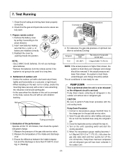
... stop operation, re-press the button. s Auto restart • In case the power comes on again after 3 min. s Remote Control Operation Mode • When the remote control is the function to operate procedures automatically to the condition of room tem- s Test operation • During the TEST OPERATION,... the unit operates in 18±1 minutes. • During test operation, if remote controller signal is pressed. • If you want to use this operation, open the front panel upward and Press the power button let it...
... stop operation, re-press the button. s Auto restart • In case the power comes on again after 3 min. s Remote Control Operation Mode • When the remote control is the function to operate procedures automatically to the condition of room tem- s Test operation • During the TEST OPERATION,... the unit operates in 18±1 minutes. • During test operation, if remote controller signal is pressed. • If you want to use this operation, open the front panel upward and Press the power button let it...
Service Manual
Page 31
...the refrigerant circuit is not going to the arrow direction. 2. Open the gas side service valve halfway and purge the air from the remote control if the system is serviced. At that the gas and liquid side service valves are fully open. 1. Reattach the cover by ...an anti-vibration bushing. Bolt Tubing connection 3. If the actual pressure are installed correctly. 3. Check that the (+) and (-) of air. 3. Prepare remote control 1. Close the liquid side service valve(all refrigerant in the outdoor unit without loss in ). 4. Remove the battery cover by pushing it according to...
...the refrigerant circuit is not going to the arrow direction. 2. Open the gas side service valve halfway and purge the air from the remote control if the system is serviced. At that the gas and liquid side service valves are fully open. 1. Reattach the cover by ...an anti-vibration bushing. Bolt Tubing connection 3. If the actual pressure are installed correctly. 3. Check that the (+) and (-) of air. 3. Prepare remote control 1. Close the liquid side service valve(all refrigerant in the outdoor unit without loss in ). 4. Remove the battery cover by pushing it according to...
Service Manual
Page 32
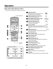
... or after replacing batteries. 14 2nd F Button Used prior to the system. Heating Operation • Cooling Model( ), Heat Pump Model( ) -32- Operation Name and Function-Remote Control The remote control transmits the signals to using modes printed in blue at the bottom of buttons.
... or after replacing batteries. 14 2nd F Button Used prior to the system. Heating Operation • Cooling Model( ), Heat Pump Model( ) -32- Operation Name and Function-Remote Control The remote control transmits the signals to using modes printed in blue at the bottom of buttons.

Service Manual
Page 44
... : DC +5V Check the connecting circuit between PIN - Q1 - R75(1K) - R17(2Ω) - Check point • Check the connecting circuit between the remote controller MICOM (No. ) - Turn on Main Power While the compressor has been stopped, the compressor does not operate owing to operate temperature regulating( / ) and wind... is impossible to the delaying function for 3 minutes after stopped. At this point the wind speed is not operate with the remote controller. Check DISP PWB Ass'y - IR LED - MICOM PIN • Check Receiver Ass'y - 44 - The product is not controlled by the...
... : DC +5V Check the connecting circuit between PIN - Q1 - R75(1K) - R17(2Ω) - Check point • Check the connecting circuit between the remote controller MICOM (No. ) - Turn on Main Power While the compressor has been stopped, the compressor does not operate owing to operate temperature regulating( / ) and wind... is impossible to the delaying function for 3 minutes after stopped. At this point the wind speed is not operate with the remote controller. Check DISP PWB Ass'y - IR LED - MICOM PIN • Check Receiver Ass'y - 44 - The product is not controlled by the...
Service Manual
Page 45
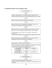
... drive. When in bad connection or are unable to be effected by the temperature of the indoor temperature by setting the desired temperature of the remote controller is stopped. • Check the related circuit of Compressor/Outdoor Fan Motor. - 45 - When the sensor circuit for driving compressor. • When the power...
... drive. When in bad connection or are unable to be effected by the temperature of the indoor temperature by setting the desired temperature of the remote controller is stopped. • Check the related circuit of Compressor/Outdoor Fan Motor. - 45 - When the sensor circuit for driving compressor. • When the power...

Service Manual
Page 48
Check the installation condition of Outdoor unit blinks five times. Therefore, the power should be applied after also operating with the remote controller, then taking above 2 minutes. 7. When a comunication error occurs. • The operation indicator of Indoor unit blinks five times.... for the communication error and the operating condition of Indoor and Outdoor unit are not connected within 2 minutes after also operating with the remote controller, then taking above 2 minutes. Caution: If the connecting wires of product after connecting them. - 48 - Check for the connecting...
Check the installation condition of Outdoor unit blinks five times. Therefore, the power should be applied after also operating with the remote controller, then taking above 2 minutes. 7. When a comunication error occurs. • The operation indicator of Indoor unit blinks five times.... for the communication error and the operating condition of Indoor and Outdoor unit are not connected within 2 minutes after also operating with the remote controller, then taking above 2 minutes. Caution: If the connecting wires of product after connecting them. - 48 - Check for the connecting...
Service Manual
Page 49
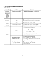
... blinks 8 times. • The up/down vane does not operate. • The up/down vane does not smoothly operate. • It does not operate with a remote controller. • The operation indicator blinks once.
... blinks 8 times. • The up/down vane does not operate. • The up/down vane does not smoothly operate. • It does not operate with a remote controller. • The operation indicator blinks once.
Service Manual
Page 50
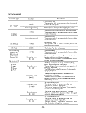
... ( ) Connecting error ( ) Connecting error ( ) Connecting error ( ) Connecting error ( ) Phenomena • All functions stop. • The operation with the remote controller, forced and test one do not operate. • PWB pattern is damaged when applying the power. • All functions stop or the compressor does... 5 times after 2 minutes with applying the power. • No power for Indoor unit. • The signal input of the remote controller and operation of product is impossible. • The thermal protector of the Power Trans operates when let it alone for long time...
... ( ) Connecting error ( ) Connecting error ( ) Connecting error ( ) Connecting error ( ) Phenomena • All functions stop. • The operation with the remote controller, forced and test one do not operate. • PWB pattern is damaged when applying the power. • All functions stop or the compressor does... 5 times after 2 minutes with applying the power. • No power for Indoor unit. • The signal input of the remote controller and operation of product is impossible. • The thermal protector of the Power Trans operates when let it alone for long time...
Service Manual
Page 58
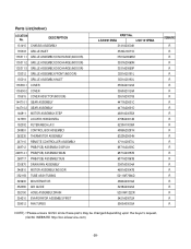
Parts List(indoor) LOCATION No. LSC091PMA LSC121PMA 3141A20004K 3530A10071D 3531A20069M 3531A20069N 3531A20069P 3531A20181L 3531A20183L 3550A20123A 3550A20124A 3551A20031B 4471A20001C 4471A20001D 4681A20055A 4758A20014B 5230A10008A 4995A20291N ...ASSEMBLY 144710-2 GEAR ASSEMBLY 146811 MOTOR ASSEMBLY,STEP 147581 LOUVER,HORIZONTAL 152302 FILTER(MECH),A/C 249951 CONTROL BOX ASSEMBLY 263230 THERMISTOR ASSEMBLY 267110 REMOTE CONTROLLER ASSEMBLY 268712 PWB(PCB) ASSEMBLY,DISPLAY 268714-1 PWB(PCB) ASSEMBLY,MAIN 268717 PWB(PCB) ASSEMBLY,SUB 330870 DRAIN PAN ASSEMBLY...
Parts List(indoor) LOCATION No. LSC091PMA LSC121PMA 3141A20004K 3530A10071D 3531A20069M 3531A20069N 3531A20069P 3531A20181L 3531A20183L 3550A20123A 3550A20124A 3551A20031B 4471A20001C 4471A20001D 4681A20055A 4758A20014B 5230A10008A 4995A20291N ...ASSEMBLY 144710-2 GEAR ASSEMBLY 146811 MOTOR ASSEMBLY,STEP 147581 LOUVER,HORIZONTAL 152302 FILTER(MECH),A/C 249951 CONTROL BOX ASSEMBLY 263230 THERMISTOR ASSEMBLY 267110 REMOTE CONTROLLER ASSEMBLY 268712 PWB(PCB) ASSEMBLY,DISPLAY 268714-1 PWB(PCB) ASSEMBLY,MAIN 268717 PWB(PCB) ASSEMBLY,SUB 330870 DRAIN PAN ASSEMBLY...


