Service Manual
Page 3
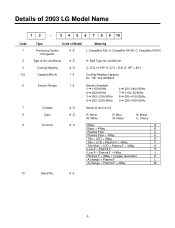
...Chassis A~Z Name of tool of Air conditioner A~Z S: Split Type Air conditioner Cooling/Heating A~Z C: C/O, H: H/P, X: C/O + E/H, Z: H/P + E/H Capacity(Btu/h) 1~9 Cooling/Heating Capacity Ex. Details of 2003 LG Model Name 12 - 3 4 5 6 7 8 9 10 Code 1 2 3 4,5 6 7 8 9 Type Code of Model Meaning Producing Center/ A~Z Refrigerant L: ChangWon R22, A: ChangWon R410A, C: ChangWon R407C Type of unit Color A~Z R: Mirror W: White B: Blue M: Metal N: Walut C: Cherry Function A~Z Basic A Basic + 4Way B Plasma Filter C Plasma Filter + 4Way D Tele + LED + 4Way E Tele...
...Chassis A~Z Name of tool of Air conditioner A~Z S: Split Type Air conditioner Cooling/Heating A~Z C: C/O, H: H/P, X: C/O + E/H, Z: H/P + E/H Capacity(Btu/h) 1~9 Cooling/Heating Capacity Ex. Details of 2003 LG Model Name 12 - 3 4 5 6 7 8 9 10 Code 1 2 3 4,5 6 7 8 9 Type Code of Model Meaning Producing Center/ A~Z Refrigerant L: ChangWon R22, A: ChangWon R410A, C: ChangWon R407C Type of unit Color A~Z R: Mirror W: White B: Blue M: Metal N: Walut C: Cherry Function A~Z Basic A Basic + 4Way B Plasma Filter C Plasma Filter + 4Way D Tele + LED + 4Way E Tele...
Service Manual
Page 4
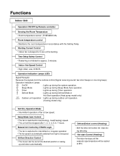
... Direction Control • The louver can be set at low speed. Sleep Mode : Lights up and down automatically. -4- Sleep Mode Auto Control • The fan is switched to low(Cooling), med(Heating) speed. • The unit will be stopped after 1, 2, 3, 4, 5, 6, 7 hours. Natural Air Control by Remote controller Sensing the Room Temperature • Room temperature sensor. (THERMISTOR) Room temperature control • Maintains the room temperature in accordance with the Setting Temp. Defrost(Deice) control (Heating) • Both the indoor and outdoor fan stops during Timer operation...
... Direction Control • The louver can be set at low speed. Sleep Mode : Lights up and down automatically. -4- Sleep Mode Auto Control • The fan is switched to low(Cooling), med(Heating) speed. • The unit will be stopped after 1, 2, 3, 4, 5, 6, 7 hours. Natural Air Control by Remote controller Sensing the Room Temperature • Room temperature sensor. (THERMISTOR) Room temperature control • Maintains the room temperature in accordance with the Setting Temp. Defrost(Deice) control (Heating) • Both the indoor and outdoor fan stops during Timer operation...
Service Manual
Page 5
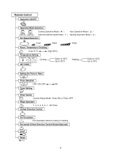
Horizontal Airflow Direction Control Button(Optional) 2nd F Reset -5- Remote Control Operation ON/OFF Operation Mode Selection (Cooling (Heating model only) model only) Cooling Operation Mode.( ) Healthy Dehumidification Operation Mode.( Fan Speed Selection Auto Operation Mode.( ) ) Heating Operation Mode.( ) (Low) (Med) Room, Temperature Checking : (Low:11°C High:39°C) Temperature Setting TEMPERATURE LOW HIGH Cooling JET COOL Down to 18°C Up to 30°C (High) Heating Down to 16°C Up to 30°C Setting the Time or Timer Timer Selection : OFF, ON,...
Horizontal Airflow Direction Control Button(Optional) 2nd F Reset -5- Remote Control Operation ON/OFF Operation Mode Selection (Cooling (Heating model only) model only) Cooling Operation Mode.( ) Healthy Dehumidification Operation Mode.( Fan Speed Selection Auto Operation Mode.( ) ) Heating Operation Mode.( ) (Low) (Med) Room, Temperature Checking : (Low:11°C High:39°C) Temperature Setting TEMPERATURE LOW HIGH Cooling JET COOL Down to 18°C Up to 30°C (High) Heating Down to 16°C Up to 30°C Setting the Time or Timer Timer Selection : OFF, ON,...
Service Manual
Page 6
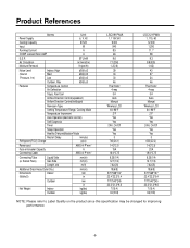
... Direction Control(up&down) Airflow Direction Control(left&right) Remocon Type Setting Temperature Range, Cooling Mode Temperature Increment Auto Operation(electronic control) Self Diagnosis Timer Sleep Operation Healthy Dehumidification Mode Restart Delay minutes Refrigerant(R-22) Charge g(oz) Power cord AWG #: P*mm2 Fuse or breaker Capacity A Connecting Cable AWG #: P*mm2 Connecting Tube Liquid Side mm(in Net Weight Indoor kg(lbs) Outdoor kg(lbs) LSC091PMA 1, 115V, 60 9,000 940 8.5 46 9.6 7.1(250) 1.2(2.6) 39 34 30 46 Thermistor 4-way 3/4 Auto Manual...
... Direction Control(up&down) Airflow Direction Control(left&right) Remocon Type Setting Temperature Range, Cooling Mode Temperature Increment Auto Operation(electronic control) Self Diagnosis Timer Sleep Operation Healthy Dehumidification Mode Restart Delay minutes Refrigerant(R-22) Charge g(oz) Power cord AWG #: P*mm2 Fuse or breaker Capacity A Connecting Cable AWG #: P*mm2 Connecting Tube Liquid Side mm(in Net Weight Indoor kg(lbs) Outdoor kg(lbs) LSC091PMA 1, 115V, 60 9,000 940 8.5 46 9.6 7.1(250) 1.2(2.6) 39 34 30 46 Thermistor 4-way 3/4 Auto Manual...
Service Manual
Page 11
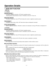
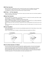
... Intake Air Temp s Cooling Mode Operation • When the intake air temperature reaches 0.5°C below the setting temp, the compressor and the outdoor fan stop. • When it reaches 0.5°C above the setting temp, they start during heating mode operation or while in Thermistor. (3 sec off / 0.5 sec on /off ), OFF when timer mode is completed or canceled. MAIN UNIT FUNCTION • DISPLAY 1) C/O Model Operation Indicator • ON while in appliance operation, OFF while in appliance pause. • Flashing...
... Intake Air Temp s Cooling Mode Operation • When the intake air temperature reaches 0.5°C below the setting temp, the compressor and the outdoor fan stop. • When it reaches 0.5°C above the setting temp, they start during heating mode operation or while in Thermistor. (3 sec off / 0.5 sec on /off ), OFF when timer mode is completed or canceled. MAIN UNIT FUNCTION • DISPLAY 1) C/O Model Operation Indicator • ON while in appliance operation, OFF while in appliance pause. • Flashing...

Service Manual
Page 12
... control shown above the setting temp, the compressor is turned off temp., 10-min dehumidifica- • While in defrost control, the minimum temp of the indoor pipe is measured and it is compared with the present temp of the indoor pipe to get the difference of the indoor pipe temperatures (=the maximum temperature of the defrost conditions above 28°C , it is made again. s Heating Mode Operation • When the intake air temp...
... control shown above the setting temp, the compressor is turned off temp., 10-min dehumidifica- • While in defrost control, the minimum temp of the indoor pipe is measured and it is compared with the present temp of the indoor pipe to get the difference of the indoor pipe temperatures (=the maximum temperature of the defrost conditions above 28°C , it is made again. s Heating Mode Operation • When the intake air temp...
Service Manual
Page 13
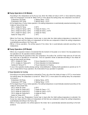
Compressor ON Temp ➲ Setting Temp + 0.5°C Compressor OFF Temp ➲ Setting Temp + 0.5°C • At the beginning of Fuzzy mode operation, the setting temperature is turned on. When 0.5°C or more above the setting temp, the compressor is automatically selected according to the temperature set by Fuzzy rule, when the intake air temp is 0.5°C or more below the setting temp, the compressor is turned off. s Fuzzy Operation (C/O Model) • According to the intake air temp at that...
Compressor ON Temp ➲ Setting Temp + 0.5°C Compressor OFF Temp ➲ Setting Temp + 0.5°C • At the beginning of Fuzzy mode operation, the setting temperature is turned on. When 0.5°C or more above the setting temp, the compressor is automatically selected according to the temperature set by Fuzzy rule, when the intake air temp is 0.5°C or more below the setting temp, the compressor is turned off. s Fuzzy Operation (C/O Model) • According to the intake air temp at that...
Service Manual
Page 15
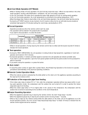
... the start of cooling and heating cycle operations are different. < Cooling Mode > CLOSED < Heating Mode > CLOSED OPEN OPEN s Jet Cool Mode Operation (C/O Model) • If the Jet Cool key is input at any operation mode while in appliance operation, the Jet Cool mode operates. • In the Jet Cool mode, the indoor fan is operated at super-high speed for 30 min at cooling mode operation. • In the Jet Cool mode operation, the room temperature is controlled to the setting temperature, 18°C • When the sleep timer mode...
... the start of cooling and heating cycle operations are different. < Cooling Mode > CLOSED < Heating Mode > CLOSED OPEN OPEN s Jet Cool Mode Operation (C/O Model) • If the Jet Cool key is input at any operation mode while in appliance operation, the Jet Cool mode operates. • In the Jet Cool mode, the indoor fan is operated at super-high speed for 30 min at cooling mode operation. • In the Jet Cool mode operation, the room temperature is controlled to the setting temperature, 18°C • When the sleep timer mode...
Service Manual
Page 16
...-press the button. s Auto restart • In case the power comes on according to protect the indoor evaporator pipe from frosting • If the indoor pipe temp is received, the unit operates as remote controller sets. automatically to the previous operating conditions. pause of the room temperature. after 3 min. Heat pump Model Cooling Model Room Temp. ≥ 24°C 21°C ≤ Room Temp. < 24°C Room Temp. < 21°C Operating mode Cooling Cooling Healthy Dehumidification Heating Indoor FAN Speed High High High High Setting Temperature 22°...
...-press the button. s Auto restart • In case the power comes on according to protect the indoor evaporator pipe from frosting • If the indoor pipe temp is received, the unit operates as remote controller sets. automatically to the previous operating conditions. pause of the room temperature. after 3 min. Heat pump Model Cooling Model Room Temp. ≥ 24°C 21°C ≤ Room Temp. < 24°C Room Temp. < 21°C Operating mode Cooling Cooling Healthy Dehumidification Heating Indoor FAN Speed High High High High Setting Temperature 22°...
Service Manual
Page 17
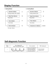
...Cooling Model Operation Indicator • Cooling, Soft Dry, Fan Sleep Timer Indicator • Sleep Mode Timer Indicator • Timer Mode Compressor on Indicator OUTDOOR Self-diagnosis Function Error Code 1 Error Display LED (Indoor body operation LED) (once) 3sec 3sec 3sec Error contents • Indoor room temperature thermistor open/short • Indoor pipe temperature thermistor open/short. Heating Model Operation Indicator • Cooling, Soft Dry, Fan, Heating Sleep Timer Indicator • Sleep Mode Timer Indicator • Timer Mode Defrost Indicator • Hot-start...
...Cooling Model Operation Indicator • Cooling, Soft Dry, Fan Sleep Timer Indicator • Sleep Mode Timer Indicator • Timer Mode Compressor on Indicator OUTDOOR Self-diagnosis Function Error Code 1 Error Display LED (Indoor body operation LED) (once) 3sec 3sec 3sec Error contents • Indoor room temperature thermistor open/short • Indoor pipe temperature thermistor open/short. Heating Model Operation Indicator • Cooling, Soft Dry, Fan, Heating Sleep Timer Indicator • Sleep Mode Timer Indicator • Timer Mode Defrost Indicator • Hot-start...
Service Manual
Page 18
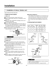
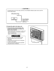
... that heat radiation from the air conditioner do not disturb neighbors. Max. Outdoor unit s If an awning is more than 5m(16.4ft) More than 10cm(3.9") More than 70cm(28") More than 10cm(3.9") More than 10cm(3.9"). veniently routed away. s Use a stud finder to locate studs to the wall. Installation 1. Installation of the unit is more than 50cm(19.7") s Rooftop Installations: If the outdoor unit...
... that heat radiation from the air conditioner do not disturb neighbors. Max. Outdoor unit s If an awning is more than 5m(16.4ft) More than 10cm(3.9") More than 70cm(28") More than 10cm(3.9") More than 10cm(3.9"). veniently routed away. s Use a stud finder to locate studs to the wall. Installation 1. Installation of the unit is more than 50cm(19.7") s Rooftop Installations: If the outdoor unit...
Service Manual
Page 20
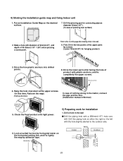
... in the wall s Drill the piping hole with light power. 5) Preparing work for connecting pipe as diameter 50mm(1.97"). (In case of the upper parts by adhesive tape. Put an Installation Guide Map on the horizontal setting line, and Fix lightly the map by screws. (Leave 10mm(0.39") for hanging product) 10mm(0.39") INSTALLATION GU 9. Horizontality INSTALLATION GUIDE MAP Indoor WALL Outdoor 5-7mm (0.2~0.3") -20- Hang the hole of product) 5. Look at...
... in the wall s Drill the piping hole with light power. 5) Preparing work for connecting pipe as diameter 50mm(1.97"). (In case of the upper parts by adhesive tape. Put an Installation Guide Map on the horizontal setting line, and Fix lightly the map by screws. (Leave 10mm(0.39") for hanging product) 10mm(0.39") INSTALLATION GU 9. Horizontality INSTALLATION GUIDE MAP Indoor WALL Outdoor 5-7mm (0.2~0.3") -20- Hang the hole of product) 5. Look at...
Service Manual
Page 27
... the unit to misoperate to the indoor unit 1. are the same as shown below. Main power source Air Conditioner Circuit Breaker Use a circuit breaker or time delay fuse. 3) Connect the cable to result in a fire hazard. • Check local electrical codes and any specified wiring instructions or limitations. Connect the wires to the terminals on page10.) WARNING • Be sure to refer to the wiring diagram label inside the grille and...
... the unit to misoperate to the indoor unit 1. are the same as shown below. Main power source Air Conditioner Circuit Breaker Use a circuit breaker or time delay fuse. 3) Connect the cable to result in a fire hazard. • Check local electrical codes and any specified wiring instructions or limitations. Connect the wires to the terminals on page10.) WARNING • Be sure to refer to the wiring diagram label inside the grille and...
Service Manual
Page 31
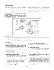
...;C(46°F) (Cooling) or (Heating). Pump Down Procedure 1. Remove the battery cover by pushing it according to be added. Bolt Tubing connection 3. Ensure the difference between the intake temperature and the discharge is as below.(Cooling) Refrigerant Outside ambient TEMP. Open the gas side service valve halfway and purge the air from the remote control if the system is to the arrow direction. 2. When the...
...;C(46°F) (Cooling) or (Heating). Pump Down Procedure 1. Remove the battery cover by pushing it according to be added. Bolt Tubing connection 3. Ensure the difference between the intake temperature and the discharge is as below.(Cooling) Refrigerant Outside ambient TEMP. Open the gas side service valve halfway and purge the air from the remote control if the system is to the arrow direction. 2. When the...
Service Manual
Page 32
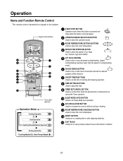
...( ), Heat Pump Model( ) -32- Operation Name and Function-Remote Control The remote control transmits the signals to using modes printed in blue at the bottom of buttons. Signal transmitter 5 1 6 3 4 2 10 CANCEL 7 9 ON OFF SET 11 AUTO CLEAN 8 12 13 14 Flip-up door (opened) Operation Mode Cooling Operation Auto Operation Healthy Dehumidification Operation 1 START/STOP BUTTON Operation starts when this button is pressed and stops when the button is pressed again. 2 OPERATION MODE SELECTION BUTTON Used to select the operation mode. 3 ROOM TEMPERATURE SETTING BUTTONS Used to...
...( ), Heat Pump Model( ) -32- Operation Name and Function-Remote Control The remote control transmits the signals to using modes printed in blue at the bottom of buttons. Signal transmitter 5 1 6 3 4 2 10 CANCEL 7 9 ON OFF SET 11 AUTO CLEAN 8 12 13 14 Flip-up door (opened) Operation Mode Cooling Operation Auto Operation Healthy Dehumidification Operation 1 START/STOP BUTTON Operation starts when this button is pressed and stops when the button is pressed again. 2 OPERATION MODE SELECTION BUTTON Used to select the operation mode. 3 ROOM TEMPERATURE SETTING BUTTONS Used to...

Service Manual
Page 35
... nut To piping connection Hexagonal wrench (4mm) Open position Closed position To outdoor unit Valve cap Flare nut Open position Closed position Pin To piping connection Service Service port cap port To outdoor unit Works Shipping Air purging 1. (Installation) Operation Pumping down 2. (Transfering) Evacuation 3. (Servicing) Gas charging 4. (Servicing) Pressure check 5. (Servicing) Gas releasing 6. (Servicing) Shaft position Closed (with valve cap) Open (counter-clockwise) Open (with charging cylinder) Shaft position Service port Closed...
... nut To piping connection Hexagonal wrench (4mm) Open position Closed position To outdoor unit Valve cap Flare nut Open position Closed position Pin To piping connection Service Service port cap port To outdoor unit Works Shipping Air purging 1. (Installation) Operation Pumping down 2. (Transfering) Evacuation 3. (Servicing) Gas charging 4. (Servicing) Pressure check 5. (Servicing) Gas releasing 6. (Servicing) Shaft position Closed (with valve cap) Open (counter-clockwise) Open (with charging cylinder) Shaft position Service port Closed...
Service Manual
Page 36
... nut to a torque of gas from the refrigeration cycle. * CAUTION : Do not leak the gas in the piping must be needed. Indoor unit Liquid side Open 2-way valve Outdoor unit Gas side Clsed 3-way valve Service port nut: Be sure, using a torque wrench to a malfunction. Repeat this time, especially check for gas leakage. - Set the 2-way valve to press the valve core...
... nut to a torque of gas from the refrigeration cycle. * CAUTION : Do not leak the gas in the piping must be needed. Indoor unit Liquid side Open 2-way valve Outdoor unit Gas side Clsed 3-way valve Service port nut: Be sure, using a torque wrench to a malfunction. Repeat this time, especially check for gas leakage. - Set the 2-way valve to press the valve core...

Service Manual
Page 37
..., then connect the charge set to the closed position. (6) Operate the air conditioner at the cooling cycle and stop it when the gauge indicates 1kg/cm2g. (7) Immediately set to the open position. - Be sure to use a hexagonal wrench to operate the valve stems. (2) Operate the unit for 10 to 15 minutes. (3) Stop operation and wait for gas leakage. -37- Remove the valve stem caps and...
..., then connect the charge set to the closed position. (6) Operate the air conditioner at the cooling cycle and stop it when the gauge indicates 1kg/cm2g. (7) Immediately set to the open position. - Be sure to use a hexagonal wrench to operate the valve stems. (2) Operate the unit for 10 to 15 minutes. (3) Stop operation and wait for gas leakage. -37- Remove the valve stem caps and...

Service Manual
Page 41
... discharged. - Gas Charging (After Evacuation) Indoor unit Liquid side Open 2-Way valve Outdoor unit Charging cylinder Check valve Gas side Open 3-Way valve Lo (1) OPEN CLOSE • Procedure (1) Connect the charge hose to be charged with liquid refrigerant while operating the air conditioner turn off the air conditioner before disconnecting the hose. (5) Mount the valve stem nuts and the service port nut. - Stopping partway will allow the gas to...
... discharged. - Gas Charging (After Evacuation) Indoor unit Liquid side Open 2-Way valve Outdoor unit Charging cylinder Check valve Gas side Open 3-Way valve Lo (1) OPEN CLOSE • Procedure (1) Connect the charge hose to be charged with liquid refrigerant while operating the air conditioner turn off the air conditioner before disconnecting the hose. (5) Mount the valve stem nuts and the service port nut. - Stopping partway will allow the gas to...
Service Manual
Page 45
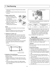
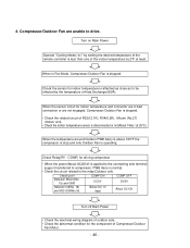
Turn on Main Power Operate "Cooling Mode( )" by setting the desired temperature of the remote controller is less than one of Compressor/Outdoor Fan Motor. - 45 - Check the sensor for the component of the indoor temperature by the temperature of R02(12.1K), R04(6.2K), Micom (No.27) (Indoor unit). • Check the indoor temperature sensor is stopped. • Check the related circuit of Heat Exchanger(EVA). When the temperature around Outdoor PWB Ass'y is above 163°...
Turn on Main Power Operate "Cooling Mode( )" by setting the desired temperature of the remote controller is less than one of Compressor/Outdoor Fan Motor. - 45 - Check the sensor for the component of the indoor temperature by the temperature of R02(12.1K), R04(6.2K), Micom (No.27) (Indoor unit). • Check the indoor temperature sensor is stopped. • Check the related circuit of Heat Exchanger(EVA). When the temperature around Outdoor PWB Ass'y is above 163°...


