Service Manual
Page 2
Contents Details of 2003 LG Model Name 3 Functions ...4 Product References ...6 Dimensions ...7 Refrigeration Cycle Diagram 9 Wiring Diagram...10 Operation Details ...11 Display Function ...17 Self-diagnosis Function...17 Installation ...18 Operation ...33 Disassembly of the parts (Indoor Unit 33 2-way, 3-way Valve...35 Cycle Troubleshooting Guide 42 Electronic Control Device...52 Schematic Diagram ...55 Exploded View and Replacement Parts List 57 -2-
Contents Details of 2003 LG Model Name 3 Functions ...4 Product References ...6 Dimensions ...7 Refrigeration Cycle Diagram 9 Wiring Diagram...10 Operation Details ...11 Display Function ...17 Self-diagnosis Function...17 Installation ...18 Operation ...33 Disassembly of the parts (Indoor Unit 33 2-way, 3-way Valve...35 Cycle Troubleshooting Guide 42 Electronic Control Device...52 Schematic Diagram ...55 Exploded View and Replacement Parts List 57 -2-
Service Manual
Page 3
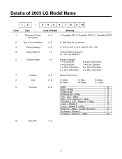
Details of 2003 LG Model Name 12 - 3 4 5 6 7 8 9 10 Code 1 2 3 4,5 6 7 8 9 Type Code of Model Meaning Producing Center/ A~Z Refrigerant L: ChangWon R22, A: ChangWon R410A, C: ChangWon R407C Type of unit Color A~Z R: Mirror W: White B: Blue M: Metal N: Walut C: Cherry Function A~Z Basic A Basic + 4Way B Plasma Filter C Plasma Filter + 4Way D ...
Details of 2003 LG Model Name 12 - 3 4 5 6 7 8 9 10 Code 1 2 3 4,5 6 7 8 9 Type Code of Model Meaning Producing Center/ A~Z Refrigerant L: ChangWon R22, A: ChangWon R410A, C: ChangWon R407C Type of unit Color A~Z R: Mirror W: White B: Blue M: Metal N: Walut C: Cherry Function A~Z Basic A Basic + 4Way B Plasma Filter C Plasma Filter + 4Way D ...
Service Manual
Page 6
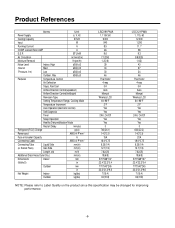
... Setting Temperature Range, Cooling Mode Temperature Increment Auto Operation(electronic control) Self Diagnosis Timer Sleep Operation Healthy Dehumidification Mode Restart Delay minutes Refrigerant(R-22) Charge g(oz) Power cord AWG #: P*mm2 Fuse or breaker Capacity A Connecting Cable AWG #: P*mm2 Connecting Tube Liquid...14:3*2.5 15A 16:4*0.75 6.35(1/4) 12.7(1/2) 7.62(25) 19(6/8) 570*568*137 22.4*22.3*5.4 770*540*245 30.3*21.3*9.6 7(15.4) 33(72.8) LSC121PMA 1, 115, 60 12,000 1,290 11.7 58 9.3 8.8(330) 1.4(3) 43 37 34 46 Thermistor 4-way 3/4 Auto Manual Wireless LCD 64~86°...
... Setting Temperature Range, Cooling Mode Temperature Increment Auto Operation(electronic control) Self Diagnosis Timer Sleep Operation Healthy Dehumidification Mode Restart Delay minutes Refrigerant(R-22) Charge g(oz) Power cord AWG #: P*mm2 Fuse or breaker Capacity A Connecting Cable AWG #: P*mm2 Connecting Tube Liquid...14:3*2.5 15A 16:4*0.75 6.35(1/4) 12.7(1/2) 7.62(25) 19(6/8) 570*568*137 22.4*22.3*5.4 770*540*245 30.3*21.3*9.6 7(15.4) 33(72.8) LSC121PMA 1, 115, 60 12,000 1,290 11.7 58 9.3 8.8(330) 1.4(3) 43 37 34 46 Thermistor 4-way 3/4 Auto Manual Wireless LCD 64~86°...
Service Manual
Page 9
..., 12K 20g Ex) 9K: When installed at a distance of 15m, 148g of refrigerant should be added for each meter. Refrigeration Cycle Diagram • Cooling Only Models INDOOR UNIT OUTDOOR UNIT LIQUID SIDE CAPILLARY TUBE HEAT EXCHANGER (EVAPORATOR) GAS SIDE HEAT EXCHANGER (CONDENSER) COMPRESSOR MODEL 9K, ...:ø) Gas Liquid 1/2" 1/4" Piping length Rated Max 7.62m(25ft) 15m(50ft) Elevation Rated Max 5m(16ft) 7m(23ft) For installation over rated, *a proper quantity of refrigerant should be added. (15-7.62) x 20g = 148g -9-
..., 12K 20g Ex) 9K: When installed at a distance of 15m, 148g of refrigerant should be added for each meter. Refrigeration Cycle Diagram • Cooling Only Models INDOOR UNIT OUTDOOR UNIT LIQUID SIDE CAPILLARY TUBE HEAT EXCHANGER (EVAPORATOR) GAS SIDE HEAT EXCHANGER (CONDENSER) COMPRESSOR MODEL 9K, ...:ø) Gas Liquid 1/2" 1/4" Piping length Rated Max 7.62m(25ft) 15m(50ft) Elevation Rated Max 5m(16ft) 7m(23ft) For installation over rated, *a proper quantity of refrigerant should be added. (15-7.62) x 20g = 148g -9-
Service Manual
Page 18
... and plants in front of reliability. • Oil trap should have any heat or steam near a doorway. essary damage to prevent unnec- Additional Elevation length Refrigerant B (m) A (m) (g/m) 7 15 (23ft) (50ft) 20 7 15 (23ft) (50ft) 20 More than 2m(6.6ft) More than 50cm(19.7") Outdoor unit Indoor unit CAUTION Install the indoor unit...
... and plants in front of reliability. • Oil trap should have any heat or steam near a doorway. essary damage to prevent unnec- Additional Elevation length Refrigerant B (m) A (m) (g/m) 7 15 (23ft) (50ft) 20 7 15 (23ft) (50ft) 20 More than 2m(6.6ft) More than 50cm(19.7") Outdoor unit Indoor unit CAUTION Install the indoor unit...
Service Manual
Page 24
... mount the conduit tubes on the conduit panel. 3. shows field wiring. 2. Dismount caps on the conduit panel. 4. Refer to "How to connect wiring to touch refrigerant tubing, the compressor or any moving parts. Use outdoor and waterproof connection cable rated more than the required length for 115V models. Use lock nuts...
... mount the conduit tubes on the conduit panel. 3. shows field wiring. 2. Dismount caps on the conduit panel. 4. Refer to "How to connect wiring to touch refrigerant tubing, the compressor or any moving parts. Use outdoor and waterproof connection cable rated more than the required length for 115V models. Use lock nuts...
Service Manual
Page 28
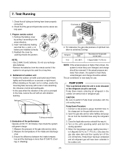
...8226; Pressure in the system rises. • Operating current rises. • Cooling(or heating) efficiency drops. • Moisture in the refrigerant system have been properly connected and all joints of parts in the refrigera- When the system pressure is not available, use a manifold valve for... leaks with vacuum pump 1. Air Purging 1) Air purging Air and moisture remaining in the refrigerant circuit may freeze and block capillary tubing. • Water may lead to this stage. 2. Leak test • Connect the manifold valve(...
...8226; Pressure in the system rises. • Operating current rises. • Cooling(or heating) efficiency drops. • Moisture in the refrigerant system have been properly connected and all joints of parts in the refrigera- When the system pressure is not available, use a manifold valve for... leaks with vacuum pump 1. Air Purging 1) Air purging Air and moisture remaining in the refrigerant circuit may freeze and block capillary tubing. • Water may lead to this stage. 2. Leak test • Connect the manifold valve(...
Service Manual
Page 31
... on the unit's operating switch and start the cooling operation. 5. Insert new batteries making sure that time, Pump Down has been completed and all refrigerant in the outdoor unit without loss in ). 4. NOTE: • Use 2 AAA(1.5volt) batteries. Measure the pressure of air. 3. Discharge air... conditioner is most likely undercharged, and charge should be used for a long time. 2. Evaluation of the unit is as below.(Cooling) Refrigerant Outside ambient TEMP. The pressure of battery are lower than shown, the system is most likely over-charged, and charge should be relocated...
... on the unit's operating switch and start the cooling operation. 5. Insert new batteries making sure that time, Pump Down has been completed and all refrigerant in the outdoor unit without loss in ). 4. NOTE: • Use 2 AAA(1.5volt) batteries. Measure the pressure of air. 3. Discharge air... conditioner is most likely undercharged, and charge should be used for a long time. 2. Evaluation of the unit is as below.(Cooling) Refrigerant Outside ambient TEMP. The pressure of battery are lower than shown, the system is most likely over-charged, and charge should be relocated...
Service Manual
Page 36
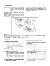
... step (3) above, take the following mesures : If the gas leaks stop when the connections are tightened further, continue working from the refrigeration cycle. * CAUTION : Do not leak the gas in the refrigeration pipes, it prevents the gas leakage from step (4). If air remains in the air during Air purging. • Procedure (1) Recheck...
... step (3) above, take the following mesures : If the gas leaks stop when the connections are tightened further, continue working from the refrigeration cycle. * CAUTION : Do not leak the gas in the refrigeration pipes, it prevents the gas leakage from step (4). If air remains in the air during Air purging. • Procedure (1) Recheck...
Service Manual
Page 38
... leak the gas in the air during Air Purging. -38- Purge the air by loosening the flare nut on the gas cylinder and discharge the refrigerant until the gauge indicates 3 to 5 kg/cm2g. (6) Disconnect the charge set and the gas cylinder, and set and a gas cylinder to the...torque of the 3-way valve. - Close the valve on the 2-way valve approximately 45° for 3 seconds then closing it for gas leakage. (5) Discharge the refrigerant. - repeat 3 times. - Open the valves on the gas cylinder closed position. (2) Connect the charge set the 2-way and 3-way valves to the open position....
... leak the gas in the air during Air Purging. -38- Purge the air by loosening the flare nut on the gas cylinder and discharge the refrigerant until the gauge indicates 3 to 5 kg/cm2g. (6) Disconnect the charge set and the gas cylinder, and set and a gas cylinder to the...torque of the 3-way valve. - Close the valve on the 2-way valve approximately 45° for 3 seconds then closing it for gas leakage. (5) Discharge the refrigerant. - repeat 3 times. - Open the valves on the gas cylinder closed position. (2) Connect the charge set the 2-way and 3-way valves to the open position....
Service Manual
Page 39
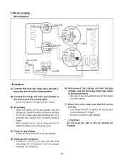
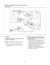
...side) on the charge set closed. - If there is no air in the refrigerant cycle (the pressure when the air conditioner is not running is discharged too suddenly, the refrigeration oil will not be discharged. -39- 2) Balance refrigerant of the 2-way, 3-way valves (Gas leakage) Indoor unit Liquid side 2-Way...CLOSE • Procedure (1) Confirm that both the 2-way and 3-way valves are set to the back seat. (2) Connect the charge set and discharge the refrigerant until the gauge indicates 0.5 to 1 kg/cm2G. Leave the valve on the charge set to the 3-way valve's port. - if this is the ...
...side) on the charge set closed. - If there is no air in the refrigerant cycle (the pressure when the air conditioner is not running is discharged too suddenly, the refrigeration oil will not be discharged. -39- 2) Balance refrigerant of the 2-way, 3-way valves (Gas leakage) Indoor unit Liquid side 2-Way...CLOSE • Procedure (1) Confirm that both the 2-way and 3-way valves are set to the back seat. (2) Connect the charge set and discharge the refrigerant until the gauge indicates 0.5 to 1 kg/cm2G. Leave the valve on the charge set to the 3-way valve's port. - if this is the ...

Service Manual
Page 40
... pump oil becomes dirty or depleted, replenish as needed. -40- Vacuum pump oil. 3. Confirm that the gauge needle has moved toward -76 cmHg (vacuum of refrigerant leaked) Indoor unit Liquid side 2-Way valve Open Outdoor unit Gas side 3-Way valve Open Vacuum pump OPEN Lo CLOSE • Procedure (1) Connect the vacuum...
... pump oil becomes dirty or depleted, replenish as needed. -40- Vacuum pump oil. 3. Confirm that the gauge needle has moved toward -76 cmHg (vacuum of refrigerant leaked) Indoor unit Liquid side 2-Way valve Open Outdoor unit Gas side 3-Way valve Open Vacuum pump OPEN Lo CLOSE • Procedure (1) Connect the vacuum...

Service Manual
Page 41
...set to the valve at the bottom of the cylinder and press the check valve on the charge set and charge the system with liquid refrigerant while operating the air conditioner turn off the air conditioner before disconnecting the hose. (5) Mount the valve stem nuts and the service port ...for gas leakage. -41- If you disconnected from the vacuum pump to purge the air. (Be careful of refrigerant, it can not be charged with larger amounts of liquid refrigerant while operating the air conditioner. (4) Immediately disconnect the charge hose from previous procedures. Open the valve at the ...
...set to the valve at the bottom of the cylinder and press the check valve on the charge set and charge the system with liquid refrigerant while operating the air conditioner turn off the air conditioner before disconnecting the hose. (5) Mount the valve stem nuts and the service port ...for gas leakage. -41- If you disconnected from the vacuum pump to purge the air. (Be careful of refrigerant, it can not be charged with larger amounts of liquid refrigerant while operating the air conditioner. (4) Immediately disconnect the charge hose from previous procedures. Open the valve at the ...
Service Manual
Page 42
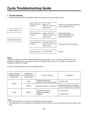
...difference is low. Trouble analysis 1. difference :approx. 8°C(14°F) Current :less than 80% of rated current Refrigerant leakage Clog of operation. Check temperature and pressure of Trouble Description Higher High Normal Defective compressor Defective 4-way reversing valve... Current is usually 4.5~5.0 kg/cm2G at the beginning of refrigeration cycle Defective compressor Temp. The suction pressure is low. Cycle Troubleshooting Guide 1. difference :over 8°C(14°F) ...
...difference is low. Trouble analysis 1. difference :approx. 8°C(14°F) Current :less than 80% of rated current Refrigerant leakage Clog of operation. Check temperature and pressure of Trouble Description Higher High Normal Defective compressor Defective 4-way reversing valve... Current is usually 4.5~5.0 kg/cm2G at the beginning of refrigeration cycle Defective compressor Temp. The suction pressure is low. Cycle Troubleshooting Guide 1. difference :over 8°C(14°F) ...
