
Owner's Manual
Page 2
... Open the Display. There is faulty in potential electrical shock or fire hazards. Do not place the display on the product screen. To Prevent Fire or Hazards : Always turn the display OFF if you have not been designed for a replacement. It can be left unattended for replacement. If you use , and servicing. If the power cable is Dangerous High Voltage inside . The power supply cord...
... Open the Display. There is faulty in potential electrical shock or fire hazards. Do not place the display on the product screen. To Prevent Fire or Hazards : Always turn the display OFF if you have not been designed for a replacement. It can be left unattended for replacement. If you use , and servicing. If the power cable is Dangerous High Voltage inside . The power supply cord...
Owner's Manual
Page 3
... these openings are not covered by placing the display on the product. However, this product. Do not use a screen saver on a bed, sofa, rug, etc. On Disposal The fluorescent lamp used under any mode except the recommended resolution, some afterimages. Therefore, NEVER: Block the bottom ventilation slots by the warranty on the screen for a long time as Red, Green or Blue spots...
... these openings are not covered by placing the display on the product. However, this product. Do not use a screen saver on a bed, sofa, rug, etc. On Disposal The fluorescent lamp used under any mode except the recommended resolution, some afterimages. Therefore, NEVER: Block the bottom ventilation slots by the warranty on the screen for a long time as Red, Green or Blue spots...
Owner's Manual
Page 5
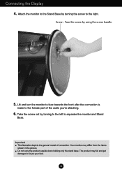
... holding only the stand base. Attach the monitor to the Stand Base by turning to the left to the female part of connection. Important This illustration depicts the general model of the cable you're attaching. 6. Lift and turn the monitor to face towards the front after the connection is made to separate the monitor and Stand Base. Connecting the Display 4. Screw : Turn the screw by using the screw handle. 5. Your monitor may fall...
... holding only the stand base. Attach the monitor to the Stand Base by turning to the left to the female part of connection. Important This illustration depicts the general model of the cable you're attaching. 6. Lift and turn the monitor to face towards the front after the connection is made to separate the monitor and Stand Base. Connecting the Display 4. Screw : Turn the screw by using the screw handle. 5. Your monitor may fall...
Owner's Manual
Page 6
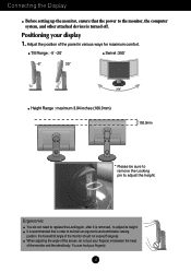
... monitor and the stand body. You can hurt your finger(s). A5 Ergonomic You do not put your display 1. Tilt Range : -5˚~20˚ Swivel :350˚ Height Range : maximum 3.94 inches (100.0mm) 100.0mm * Please be sure to remove the Locking pin to maintain an ergonomic and comfortable viewing position, the forward tilt angle of the panel in order to adjust the height. It is turned...
... monitor and the stand body. You can hurt your finger(s). A5 Ergonomic You do not put your display 1. Tilt Range : -5˚~20˚ Swivel :350˚ Height Range : maximum 3.94 inches (100.0mm) 100.0mm * Please be sure to remove the Locking pin to maintain an ergonomic and comfortable viewing position, the forward tilt angle of the panel in order to adjust the height. It is turned...
Owner's Manual
Page 7
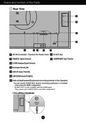
... the Parts Rear View 9 8 OUT AUDIO 2 1 COMPONENT AC-IN DC-OUT HDMI/DVI Y PB PR D-SUB 7 6 1 23 4 5 1 AC-IN Connector : Connect the Power Cord 2 DC-OUT Jack 3 HDMI/DVI Signal Connector 4 COMPONENT Input Terminal 5 D-SUB Analogue Signal Connector 6 Kensington Security Slot 7 USB UP stream Port(1EA) 8 USB DOWN stream Port(2EA) 9 Audio out Jack(Headset/Earphone/connecting terminal of the Speaker) : You can use the AUDIO-OUT Jack by connecting earphones or a headset when using the HDMI configuration.. *AUDIO...
... the Parts Rear View 9 8 OUT AUDIO 2 1 COMPONENT AC-IN DC-OUT HDMI/DVI Y PB PR D-SUB 7 6 1 23 4 5 1 AC-IN Connector : Connect the Power Cord 2 DC-OUT Jack 3 HDMI/DVI Signal Connector 4 COMPONENT Input Terminal 5 D-SUB Analogue Signal Connector 6 Kensington Security Slot 7 USB UP stream Port(1EA) 8 USB DOWN stream Port(2EA) 9 Audio out Jack(Headset/Earphone/connecting terminal of the Speaker) : You can use the AUDIO-OUT Jack by connecting earphones or a headset when using the HDMI configuration.. *AUDIO...
Owner's Manual
Page 8
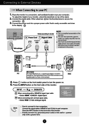
... adjust the height of your display may differ from the view as shown. This rear view represents a general model; your monitor, unlock the stand lock on the wall or a power strip with ferrite cores to a 15 pin 2 row connector. 4. Press button on the front switch panel to a grounded power outlet on top of the rear view. INPUT OK/AUTO A When connecting with a D-Sub signal cable. • Select RGB : D-Sub analogue signal. B When connecting with a HDMI/DVI signal input cable. • Select HDMI : HDMI/DVI digital signal. Connect...
... adjust the height of your display may differ from the view as shown. This rear view represents a general model; your monitor, unlock the stand lock on the wall or a power strip with ferrite cores to a 15 pin 2 row connector. 4. Press button on the front switch panel to a grounded power outlet on top of the rear view. INPUT OK/AUTO A When connecting with a D-Sub signal cable. • Select RGB : D-Sub analogue signal. B When connecting with a HDMI/DVI signal input cable. • Select HDMI : HDMI/DVI digital signal. Connect...
Owner's Manual
Page 9
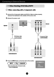
... 1 2 AUDIO OUT PB PR PB PR Monitor RCA-Stereo cable (not included) Component Cable (not included) DVD/VIDEO/HDTV PB PR PB PR DVD/VIDEO/HDTV 3. Press the INPUT button on the front side of the same color. 2. Connect the terminals to Stereo cables properly. INPUT OK/AUTO When connecting with a Component cable 1. INPUT RGB HDMI Component A8 Connect the Component cables and RCA to the sockets of the monitor. Connect the power cord. Connecting...
... 1 2 AUDIO OUT PB PR PB PR Monitor RCA-Stereo cable (not included) Component Cable (not included) DVD/VIDEO/HDTV PB PR PB PR DVD/VIDEO/HDTV 3. Press the INPUT button on the front side of the same color. 2. Connect the terminals to Stereo cables properly. INPUT OK/AUTO When connecting with a Component cable 1. INPUT RGB HDMI Component A8 Connect the Component cables and RCA to the sockets of the monitor. Connect the power cord. Connecting...
Owner's Manual
Page 10
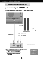
INPUT OK/AUTO When connecting with a HDMI/DVI cable 1. COMPONENT DC-OUT HDMI/DVI Y PB PR D-SUB OUT AUDIO 2 1 HDMI/DVI cable RCA-Stereo cable (not included) Speaker (not included) DVD/VIDEO/HDTV 2. Press the INPUT button at the front side of the monitor. A9 INPUT RGB HDMI Component Connecting to Stereo cables properly. Connect the HDMI/DVI cables and RCA to External Devices When Watching DVD/Video/HDTV When connecting with a HDMI/DVI cable. • Select HDMI.
INPUT OK/AUTO When connecting with a HDMI/DVI cable 1. COMPONENT DC-OUT HDMI/DVI Y PB PR D-SUB OUT AUDIO 2 1 HDMI/DVI cable RCA-Stereo cable (not included) Speaker (not included) DVD/VIDEO/HDTV 2. Press the INPUT button at the front side of the monitor. A9 INPUT RGB HDMI Component Connecting to Stereo cables properly. Connect the HDMI/DVI cables and RCA to External Devices When Watching DVD/Video/HDTV When connecting with a HDMI/DVI cable. • Select HDMI.
Owner's Manual
Page 11
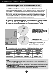
... the downstream port of the connector at the cable side matches the shape at the connecting side. Even if the display is in a power saving mode, USB compliant devices will give you can "hot" plug (attach them while the computer is an innovation in setting up to 2 other peripherals to your computer. Connecting to External Devices Connecting the USB(Universal Serial Bus) Cable "USB (Universal Serial Bus)" is...
... the downstream port of the connector at the cable side matches the shape at the connecting side. Even if the display is in a power saving mode, USB compliant devices will give you can "hot" plug (attach them while the computer is an innovation in setting up to 2 other peripherals to your computer. Connecting to External Devices Connecting the USB(Universal Serial Bus) Cable "USB (Universal Serial Bus)" is...
Owner's Manual
Page 12
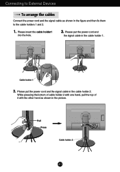
... picture. Please put the power cord and the signal cable in the cable holder 2. OUT AUDIO 2 1 Pull Press Cable holder 2 DC-OUT HDMI/DVI COMPONENT Y PB PR D-SUB A11 Connecting to External Devices To arrange the cables Connect the power cord and the signal cable as shown in the figure and then fix them to the cable holders 1 and 2. 1. Please insert the cable holder1 into the hole. 2. Please put the power cord...
... picture. Please put the power cord and the signal cable in the cable holder 2. OUT AUDIO 2 1 Pull Press Cable holder 2 DC-OUT HDMI/DVI COMPONENT Y PB PR D-SUB A11 Connecting to External Devices To arrange the cables Connect the power cord and the signal cable as shown in the figure and then fix them to the cable holders 1 and 2. 1. Please insert the cable holder1 into the hole. 2. Please put the power cord...
Owner's Manual
Page 13
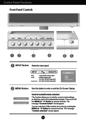
...MENU+ Button for several seconds. INPUT OK/AUTO RGB HDMI Component : 15-pin D-SUB analogue signal : HDMI/DVI digital signal DTV SET-TOP BOX,Video,DVD : DTV SET-TOP BOX,Video,DVD INPUT RGB HDMI Component MENU Button Use this button to lock the current control settings, so that they cannot be inadvertently changed. Control Panel Functions Front Panel Controls INPUT Button Select the input signal. The message "Controls unlocked" should appear. Controls locked Controls unlocked Controls locked/Controls unlocked This function allows you to enter or exit the On Screen Display...
...MENU+ Button for several seconds. INPUT OK/AUTO RGB HDMI Component : 15-pin D-SUB analogue signal : HDMI/DVI digital signal DTV SET-TOP BOX,Video,DVD : DTV SET-TOP BOX,Video,DVD INPUT RGB HDMI Component MENU Button Use this button to lock the current control settings, so that they cannot be inadvertently changed. Control Panel Functions Front Panel Controls INPUT Button Select the input signal. The message "Controls unlocked" should appear. Controls locked Controls unlocked Controls locked/Controls unlocked This function allows you to enter or exit the On Screen Display...
Owner's Manual
Page 14
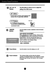
... and contrast of the PC signal (RGB, HDMI/DVI). If the display is 1920 x 1200@60Hz Power Button Use this indicator color changes to the ideal settings for the current screen resolution size (display mode). This will automatically adjust your display settings, always press the OK/AUTO button before entering the On Screen Display(OSD). Control Panel Functions Button Use this button to 1920x1200 AUTO IMAGE ADJUSTMENT When adjusting your display image to amber. A13 Auto in progress For optimal display change resolution to select an icon or adjust the setting in Sleep Mode...
... and contrast of the PC signal (RGB, HDMI/DVI). If the display is 1920 x 1200@60Hz Power Button Use this indicator color changes to the ideal settings for the current screen resolution size (display mode). This will automatically adjust your display settings, always press the OK/AUTO button before entering the On Screen Display(OSD). Control Panel Functions Button Use this button to 1920x1200 AUTO IMAGE ADJUSTMENT When adjusting your display image to amber. A13 Auto in progress For optimal display change resolution to select an icon or adjust the setting in Sleep Mode...
Owner's Manual
Page 15
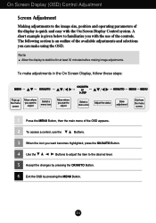
On Screen Display (OSD) Control Adjustment Screen Adjustment Making adjustments to the image size, position and operating parameters of the OSD appears. 2 To access a control, use the Buttons. 3 When the icon you want to adjust Select a menu icon Adjust the status Save adjustment Exit from the menu screen. 1 Press the MENU Button, then the main menu of the display is quick and easy with the use of the available adjustments and selections you with the On Screen Display Control system. A14 To make using the OSD. A short...
On Screen Display (OSD) Control Adjustment Screen Adjustment Making adjustments to the image size, position and operating parameters of the OSD appears. 2 To access a control, use the Buttons. 3 When the icon you want to adjust Select a menu icon Adjust the status Save adjustment Exit from the menu screen. 1 Press the MENU Button, then the main menu of the display is quick and easy with the use of the available adjustments and selections you with the On Screen Display Control system. A14 To make using the OSD. A short...
Owner's Manual
Page 17
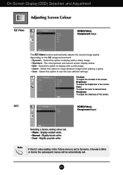
.... Brightness To adjust the brightness of the screen. Note If the EZ video setting in the Picture menu is set to Dynamic, Standard, Mild or Game the subsequent menus will be automatically set . • Warm : Slightly reddish white. • Normal : Slightly bluish white. • Cool : Slightly purplish white. Color To adjust the color to use the user-defined settings. Sharpness To adjust the clearness of the screen. HDMI(Video), Component input Selecting a factory setting colour set . A16 Contrast...
.... Brightness To adjust the brightness of the screen. Note If the EZ video setting in the Picture menu is set to Dynamic, Standard, Mild or Game the subsequent menus will be automatically set . • Warm : Slightly reddish white. • Normal : Slightly bluish white. • Cool : Slightly purplish white. Color To adjust the color to use the user-defined settings. Sharpness To adjust the clearness of the screen. HDMI(Video), Component input Selecting a factory setting colour set . A16 Contrast...
Owner's Manual
Page 19
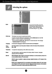
... unauthorized viewing. Child lock Language Power indicator This feature can be adjusted with PC by connecting communication between PC and monitor when DDC/CI is communication protocol for several seconds. Reset DDC-CI Use this function to set the Child lock tab to adjust and setup detailed functions on the front side of the product to the factory default. DDC/CI makes it , do the following Input Signal Window...
... unauthorized viewing. Child lock Language Power indicator This feature can be adjusted with PC by connecting communication between PC and monitor when DDC/CI is communication protocol for several seconds. Reset DDC-CI Use this function to set the Child lock tab to adjust and setup detailed functions on the front side of the product to the factory default. DDC/CI makes it , do the following Input Signal Window...
Owner's Manual
Page 23
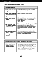
... the MENU+ button for service. Do you see a "CHECK SIGNAL CABLE" message on and the • Adjust the brightness and the contrast. You can secure the current control settings, so that they cannot be inadvertently changed. Troubleshooting Check the following before calling for several seconds: the message "Controls unlocked" will appear. No image appears G Is the power cord of the diplay's horizontal or vertical frequency range. G Do you see if the power cord is not connected...
... the MENU+ button for service. Do you see a "CHECK SIGNAL CABLE" message on and the • Adjust the brightness and the contrast. You can secure the current control settings, so that they cannot be inadvertently changed. Troubleshooting Check the following before calling for several seconds: the message "Controls unlocked" will appear. No image appears G Is the power cord of the diplay's horizontal or vertical frequency range. G Do you see if the power cord is not connected...
Owner's Manual
Page 24
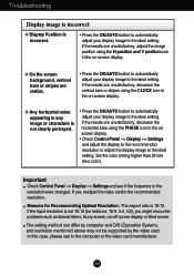
... recommended resolution. Important Check Control Panel --> Display --> Settings and see if the frequency or the resolution were changed. If the input resolution is not clearly portrayed. • Press the OK/AUTO button to automatically adjust your display image to the ideal setting. G Any horizontal noise appearing in the on screen display. Set the color setting higher than 24 bits (true color). If yes, readjust the video card to the computer or the video card manufacturer. Troubleshooting Display image is incorrect G Display Position is...
... recommended resolution. Important Check Control Panel --> Display --> Settings and see if the frequency or the resolution were changed. If the input resolution is not clearly portrayed. • Press the OK/AUTO button to automatically adjust your display image to the ideal setting. G Any horizontal noise appearing in the on screen display. Set the color setting higher than 24 bits (true color). If yes, readjust the video card to the computer or the video card manufacturer. Troubleshooting Display image is incorrect G Display Position is...
Owner's Manual
Page 25
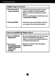
... download the driver from the display driver CD (or diskette) that comes with your display. Have you see an "Unrecognized monitor, Plug&Play (VESA DDC) monitor found" message? • Make sure to check if the video card supports Plug&Play function. Settings. Troubleshooting Display image is incorrect G The screen color is mono or abnormal. • Check if the signal cable is properly connected and use a screwdriver to fasten if necessary. • Make sure the video card is set to interlace mode...
... download the driver from the display driver CD (or diskette) that comes with your display. Have you see an "Unrecognized monitor, Plug&Play (VESA DDC) monitor found" message? • Make sure to check if the video card supports Plug&Play function. Settings. Troubleshooting Display image is incorrect G The screen color is mono or abnormal. • Check if the signal cable is properly connected and use a screwdriver to fasten if necessary. • Make sure the video card is set to interlace mode...

Owner's Manual
Page 26
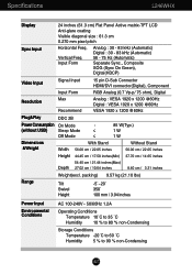
... Sync., Composite SOG (Sync On Green), Digital(HDCP) Video Input Signal Input Input Form 15 pin D-Sub Connector HDMI/DVI connector(Digital), Component RGB Analog (0.7 Vp-p/ 75 ohm), Digital Resolution Max Recommend Analog : VESA 1920 x 1200 @60Hz Digital : VESA 1920 x 1200 @60Hz VESA 1920 x 1200 @60Hz Plug&Play Power Consumption (without USB) Dimensions &Weight DDC 2B On Mode : Sleep Mode ≤ Off Mode ≤ 85 W(Typ.) 1 W 1 W With Stand Without Stand Width 56.00 cm / 22.05 inches 56.00 cm / 22.05 inches Height 44...
... Sync., Composite SOG (Sync On Green), Digital(HDCP) Video Input Signal Input Input Form 15 pin D-Sub Connector HDMI/DVI connector(Digital), Component RGB Analog (0.7 Vp-p/ 75 ohm), Digital Resolution Max Recommend Analog : VESA 1920 x 1200 @60Hz Digital : VESA 1920 x 1200 @60Hz VESA 1920 x 1200 @60Hz Plug&Play Power Consumption (without USB) Dimensions &Weight DDC 2B On Mode : Sleep Mode ≤ Off Mode ≤ 85 W(Typ.) 1 W 1 W With Stand Without Stand Width 56.00 cm / 22.05 inches 56.00 cm / 22.05 inches Height 44...
Owner's Manual
Page 28
... Sync., Composite SOG (Sync On Green), Digital(HDCP) Video Input Signal Input Input Form 15 pin D-Sub Connector HDMI/DVI connector(Digital), Component RGB Analog (0.7 Vp-p/ 75 ohm), Digital Resolution Max Recommend Analog : VESA 1920 x 1200 @60Hz Digital : VESA 1920 x 1200 @60Hz VESA 1920 x 1200 @60Hz Plug&Play DDC 2B Power Consumption (without USB) Dimensions &Weight On Mode : Sleep Mode ≤ Off Mode ≤ 85 W(Typ.) 1 W 1 W With Stand Without Stand Width 56.00 cm / 22.05 inches 56.00 cm / 22.05 inches Height 44...
... Sync., Composite SOG (Sync On Green), Digital(HDCP) Video Input Signal Input Input Form 15 pin D-Sub Connector HDMI/DVI connector(Digital), Component RGB Analog (0.7 Vp-p/ 75 ohm), Digital Resolution Max Recommend Analog : VESA 1920 x 1200 @60Hz Digital : VESA 1920 x 1200 @60Hz VESA 1920 x 1200 @60Hz Plug&Play DDC 2B Power Consumption (without USB) Dimensions &Weight On Mode : Sleep Mode ≤ Off Mode ≤ 85 W(Typ.) 1 W 1 W With Stand Without Stand Width 56.00 cm / 22.05 inches 56.00 cm / 22.05 inches Height 44...


